
Related Manuals for allen AR16


Summary of Contents for allen AR16
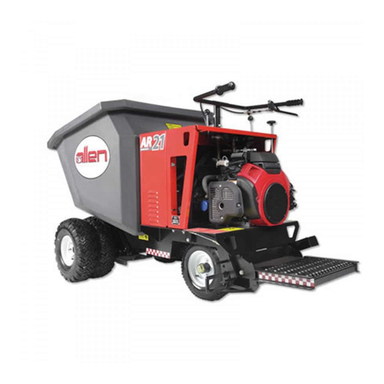
- Page 1 AR16 & AR21 W heel uggy OPERATIONS & PARTS MANUAL MANUAL PART #: 055838 | REVISION: D...
- Page 2 This manual, or a copy of it, must be kept with the machine at all times. There is a manual storage container located on the machine for your convenience. Page 2 055838...
- Page 3 OPERATIONS-PARTS MANUAL This manual covers the products listed below: Part No. Description 058806 BUGGY AR16 POLY BUCKET 13HPR NON FILL 058807 BUGGY AR16 POLY BUCKET 13HPE NON FILL 058808 BUGGY AR21 POLY BUCKET 20HPE NON FILL 058801 BUGGY AR16 POLY BUCKET 13HPR FOAM...
- Page 4 Table of Contents Page 4 055838...
-
Page 5: Table Of Contents
Handlebar Mounted Dump Lever Assembly ..... . 98 4.11 13 HP Honda Engine with Recoil and Electric Start - AR16 ..100 4.12 Electric Schematic - AR16 w/ 13HP Honda Engine(Recoil Start) . - Page 6 Allen reserves the choice to repair or replace. 2. If Allen chooses to replace the part, it will be at no cost to the customer and will be made available to the Allen Distributor, Dealer, or Rental Center from whom the End User purchased the product.
- Page 7 Complete any warranty requirements as specified by the engine manufacturer in their instructions found inside the manual box located on the back of the riding trowel operator’s seat. Your engine and clutch is not manufactured by Allen Engineering Corporation, Inc, and therefore is not covered under Allen Engineering Corporation, Inc warranty.
- Page 8 Dealer Information Your Dealer has Allen Engineering Corporation trained mechanics and original Allen replacement parts. Always contact the Allen Dealer who sold you this machine for Allen Certified repairs and replacement parts. Place Allen Dealer information below for future reference...
- Page 9 Ordering Parts Section 4.0 (page 71) contains illustrated parts lists for help in ordering replacement parts for your machine. Follow the instructions below when ordering parts to insure prompt and accurate delivery: All orders for service parts - include the serial number for the machine. Shipment will be delayed if this information is not available.
- Page 10 Model Number - Serial Number Codes Manufacturer’s Codes: When ordering parts or requesting service information, you will always be asked to specify the model and serial numbers of the machine. The legends below specifically defines each significant character or group of characters of the Model Number and Serial Number codes. Model Number AR/AT 16/20...
- Page 11 Unit Identification Unit Identification Plate Location: An identification plate listing the model number and the serial number is attached to each unit and is located on the rear lower left side of mainframe. Refer to Figure 1 for serial number and model number location.
- Page 12 Measurements in this manual are in U.S. units and their customary metric units (i.e., metric units contained within brackets [8 mm]). Machine Features for AR16: • Engine ........Honda GX390 •...
- Page 13 Technical Specifications, continued • Lift Cylinder ........2.5” Diameter [63.5mm] •...
- Page 14 Engine Specifications Honda GX390 Engine Information (13 HP) Engine Type ..........Air-cooled 4-stroke OHV Bore x Stroke.
- Page 15 Engine Specifications, continued Honda GX630 Engine Information (20 HP) Engine Type ..........Air-cooled 4-stroke OHV Bore x Stroke.
- Page 16 INTENTIONALLY LEFT BLANK Page 16 055838...
- Page 17 Section 1 SAFETY 055838 Page 17...
- Page 18 State Regulation Proposition SECTION 1 65 Warming SAFETY Page 18 055838...
- Page 19 Federal Regulation SECTION 1 Respiratory Hazard SAFETY 055838 Page 19...
- Page 20 1.1 - General Safety Precautions SECTION 1 SAFETY 1.1.1 Safety-Alert Signs This manual contains Safety-Alert Signs, as defined below, which must be followed to reduce the possibility of improper servi ce damage to the equipment or personal injury. Read and follow all Safety-Alert Signs included in this manual. NOTE defines an operating procedure, condition, etc.
- Page 21 1.2 - Spark Arrestor Notice SECTION 1 SAFETY 1.2.1 Laws Pertaining to Spark Arrestors Some states require that in certain locations arrestors be used on internal combustion engines. A spark arrester is a device designed to prevent the discharge of spark or flames from the engine exhaust. It is often required when operating equipment on forested land to prevent the risk of fires.
- Page 22 These labels can be purchased from an AEC dealer in your trade area. Should you need the name of a dealer in your area, call Allen Engineering at 800-643-0095 or email customerservice@alleneng.com.
- Page 23 1.3 - General Safety, continued SECTION 1 SAFETY b) Speed control return spring. This spring is mounted on the transmission shift bar and allows the speed control lever to return automatically when released. Spring tension should be sufficient to briskly snap back the speed control lever when it is released. Broken, damaged, or deformed springs must be replaced immediately.
- Page 24 • Extinguish smoking materials. • Shut engine off. • Shut off Fuel. On AR16 turn Fuel Valve at the carburetor to the OFF position. Note: Fuel shut off on AR21 occurs when the ignition key is turned OFF. • Let engine cool for a minimum of 5 minutes.
- Page 25 1.3 - General Safety, continued SECTION 1 SAFETY unsafe job site ventilation. Ø The engine on this machine may be equipped with an exhaust purifier that may reduce, but will not eliminate these dangerous emissions. Ø The efficiency of this purifier decreases if the engine is not properly tuned, especially if the fuel mixture is too rich.
- Page 26 SECTION 1 SAFETY NOTE: ON THE AR16 ONLY THE OUTSIDE WHEELS AND TIRES CAN BE REMOVED TO REDUCE OVERALL WIDTH. WHEN OUTSIDE WHEELS AND TIRES HAVE BEEN REMOVED OPERATE THE AR16 ONLY ON LEVEL, HARD SURFACES I.E., CONCRETE, ASPHALT, OR COMPACTED STONE.
- Page 27 1.4 - Operating Safety SECTION 1 SAFETY D) During operation of this equipment: Ø Use caution when operating near other personnel and obstructions. Always look to the rear before backing up and back up slowly. Be aware of other job site traffic. DO NOT OPERATE THIS MACHINE WITH YOUR BACK FACING THE CONTROLS.
- Page 28 1.4 - Operating Safety, continued SECTION 1 SAFETY Ø If operator must leave operator’s station (standing between handlebars either on operator’s platform or standing on the ground with the platform in the “UP” position) the operator must: a) Stop equipment. Do not block access to fire isles, stairways, fire equipment. b) Set and lock parking brake.
- Page 29 1.4 - Operating Safety, continued SECTION 1 SAFETY THIS BUGGY MUST BE CLEANED DAILY TO PREVENT CONCRETE AND DIRT BUILD-UP FROM ADVERSELY AFFECTING SAFE MACHINE OPERATION. WASH BUGGY DOWN EACH DAY WITH WATER. ØAlways clean the Buggy in an area removed from pedestrian and other machine traffic. Avoid areas where muddy surfaces can cause a Safety Hazard.
- Page 30 1.5 - Propane Operating Safety SECTION 1 SAFETY 1. Never allow your (LP) Liquid Propane-gas container to be filled above the maximum safe level as indicated by a scale or the fixed liquid level gauge (outage). Do not use the visible gauge for filling.
- Page 31 1.5 - Propane Operating Safety, continued SECTION 1 SAFETY CAUTION: USE LP-GAS CONTAINERS IN PROPER POSITION Most LP-gas appliances for cooking, heating, lighting, water heating and refrigeration are designed to operate on LP-gas vapor only. Therefore, all LP-gas containers designed for vapor service must be transported, installed and used in the proper position.
- Page 32 Notes SECTION 1 SAFETY Page 32 055838...
- Page 33 Section 2 OPERATIONS 055838 Page 33...
- Page 34 This machine is built with user safety in mind. However, it can present hazards if improperly operated and serviced. Follow operating instructions carefully. If you have any questions about operating or servicing this equipment, please contact your Allen Engineering Dealer or AEC Customer Service at 800-643-0095 or 870-236-7751. Page 34...
- Page 35 The sixteen cubic foot AR16 and the twenty-one cubic foot AR21 have earned their rank as the standard by which all power buggies are judged. Their massive two-inch thick solid steel tank- tough frames provide unparalleled strength and durability along with a lower center of gravity and ideal weight distribution.
- Page 36 2.2 - Start-up Procedures SECTION 2 OPERATIONS Page 36 055838...
- Page 37 2) Receive training on the Safety, Machine Operation, Machine Adjustments, Maintenance and Machine Lifting and Tie Down Procedures. Starting Procedures for AR16 (13 HP Honda gasoline engine) ØPosition yourself in operator’s position standing on the ground between the handlebars or standing on the operator’s platform.
- Page 38 2.2 - Start-up Procedures, continued SECTION 2 OPERATIONS ØTo start recoil start Honda GX390 13 HP, switch engine ignition switch to ON position and pull recoil starter until engine starts. After the engine starts return starter rope handle slowly against the flywheel cover of the engine.
- Page 39 2.2 - Start-up Procedures, continued SECTION 2 OPERATIONS ØInsert ignition key in start switch on engine. Turn engine start switch to START position and return switch to ON position when engine starts. ØShould the engine fail to start using the electric starter (dead battery, malfunctioning starter, etc.) the recoil starter can be used to start the engine.
- Page 40 2.3 - Parking Brake Operation SECTION 2 OPERATIONS Setting and Releasing the Parking Brake To set parking brake: 1. Stand on the operator’s platform. 2. Place right foot on brake pedal (1) and stand on the pedal so it depresses to the lowest point. 3.
- Page 41 2.4 - Battey Jump Start Procedures SECTION 2 OPERATIONS WHEN JUMP STARTING THESE HONDA ELECTRIC START ENGINES FOLLOW INSTRUCTIONS BELOW. FAILURE TO FOLLOW THESE INSTRUCTIONS CAN CAUSE BURNS AND/OR EYE INJURIES FROM ELECTRIC SPARKS, IMPROPER CONNECTIONS, ETC., TO PERSONNEL OR DAMAGE TO ENGINE. ØWear OSHA compliant safety glasses when jump starting.
-
Page 42: Operating Instructions
2.5 - Operating Instructions SECTION 2 OPERATIONS Driving Equipment ØThe Directional Control Lever (located on the top right side of the dash) controls the direction of travel - forward, reverse and neutral (free-wheeling). Select the direction of travel desired. The Speed Control Lever (located on the right side of the handle bar) controls the vehicle speed, power, and dynamic hydraulic braking. - Page 43 ØTurn fuel valve on engine to the OFF position. Failure to do so will ultimately result in gas enter- ing the crankcase. Steering the Buggy ØAllen Buggies, models AR16 and AR21 are steered using the Handlebars in front of the operator’s platform. Turning the Handlebars Clockwise will cause the Buggy to turn to the Left when traveling in the Forward Direction.
- Page 44 OUR QUALITY POLICY The Allen Engineering Team is fully committed to exceeding customer expectations for the quality of the products and services provided through the continuous improvement process of reducing waste, defects, and variability in everything we do.
- Page 45 Section 3 SERVICE 055838 Page 45...
- Page 46 3.1 - Brake Service SECTION 3 SERVICE Service Brake See page 49 for brake schematic. Inspect the Service Brake DAILY. A daily Service Brake inspection performed with an empty buggy traveling at full speed must demonstrate that when full foot pressure (125 LB.) is applied to the brake pedal both brakes engage equally, the pedal is level with the top of the operator’s platform, the buggy stops in 6-8’...
- Page 47 3.1 - Brake Service, continued SECTION 3 SERVICE Brake Operational Problem Adjustment/Repair Required Adjustment/Repair Procedure 1) Clean concrete/dirt accu- Clean all dirt from pedal area. Adjust mulation away from brake clearance of brake pedal (44) with pedal (44). pivot bolt assembly (47) by tighten- 1) Brake pedal (44) travels ing 5/8”...
- Page 48 3.2 - Parking Brake SECTION 3 SERVICE Parking Brake See page 3-5 for brake schematic. Adjust parking brake so that when engaged, parking brake will hold a loaded buggy on 15% slope (8.5 degrees). If parking brake does not operate as indicated, adjust as follows: ØAdjust service brake per the troubleshooting guide above.
- Page 49 3.2 - Parking Brake Schematic SECTION 3 SERVICE ADJUST CLEARANCE OF BRAKE PEDAL 44 WITH PIVOT BOLT ASSEMBLY 47 BY TIGHTENING 5/8”NC -10 JAM NUT AGAINST FLAT WASHERS AND 3/4” HEX NUT. THEN BACK OFF JAM NUT 1/4 TURN WHILE HOLDING PIVOT BOLT, TIGHTEN 5/8”...
-
Page 50: Speed Control
3.3 - Speed Control SECTION 3 SERVICE When making adjustments to the Speed Control system, block the buggy’s wheels in both directions to prevent injury. 1) Adjust Speed Control Lever, Cable and Spring (Refer to drawing on page ??) a) Position the buggy on a hard, level surface. Turn the engine off. Remove spark plug wire(s) to disable engine. - Page 51 3.3 - Speed Control, continued SECTION 3 SERVICE 9) Place a 5/8”NF-18 jam nut on the threaded end of both bulkhead fittings protruding through the mounting holes. 10) Attach a clevis (item 10) to the end of the cable used to attach to the transmission shift bar. Note: In all cases the cable attachments must be threaded onto the ¼”NF-28 cable end one-quar- ter of an inch(¼”).
- Page 52 3.3 - Speed Control, continued SECTION 3 SERVICE 2) Adjust Neutral The speed control assembly when properly adjusted will not permit the buggy to creep in either direction when the speed control lever is released (in neutral), the service/parking brake is released and the directional control lever is in either the forward or reverse position.
- Page 53 3.3 - Speed Control, continued SECTION 3 SERVICE CUT ONE SIDE OF RUBBER BUSHING THRU AND INSTALL CABLE 9. REF: HANDLEBAR #42126-01 INSTALL CORD GRIP IN .840” DIAMETER HOLE IN THE TOP OF CONSOLE #42100-38 TO THE LEFT REAR STEERING ASSEMBLY.
- Page 54 Relief pressure setting should be 1500 +/-50 PSI. To adjust pressure: 1. Remove hex cap (item 1) covering pressure relief valve (beside valve spool). 2. With a 5/16” allen wrench, turn pressure adjusting screw (item 2) three turns counter clockwise.
- Page 55 Relief pressure setting should be 2000 +/-50 PSI. To adjust pressure: 1. Remove hex cap (item 1) covering pressure relief valve. 2. With a 5/16” allen wrench, turn pressure adjustment screw (item 2) three turns counter clockwise. 3. Remove hex cap (item 3).
- Page 56 3.5 - Setting Engine RPM SECTION 3 SERVICE Engine Speed (RPM) 1) AR16 (13 HP Honda) ENGINE SPEED WAS ADJUSTED AT THE FACTORY TO 3,700 RPM +100/-0 WITH NO LOAD. DO NOT EXCEED THIS SPEED. If speed adjustment is required adjust as follows: 1.
- Page 57 3.5 - Setting Engine RPM, continued SECTION 3 SERVICE 2) AR21 (20 HP Honda) ENGINE SPEED WAS ADJUSTED AT THE FACTORY TO 3,000 RPM +100/-0 WITH NO LOAD. DO NOT EXCEED THIS SPEED. If speed adjustment is required adjust as follows: 1) Start engine and allow to warm up for 5 minutes.
- Page 58 3.6 - Dump Lever Adjustment SECTION 3 SERVICE Dump Control Lever 1) Console mounted dump control lever Three (3) adjustments are possible: Position of foot pedal, drag on valve lever pivot, and drag on dump pedal pivot. 1. Position of foot pedal: To readjust foot pedal position remove cotter pin (6) and clevis pin (5) at pedal.
- Page 59 3.6 - Dump Lever Adjustment, continued SECTION 3 SERVICE 2) Handle Mounted Bucket Dump Control Lever Two (2) adjustments/inspections are possible (These adjustments are made with the engine off and the parking brake engaged). A) Adjust/inspect the position of handle mounted bucket dump control lever (items 18 and 21 on the following page): To readjust the position of the handle dump lever remove bolt/nut (28) and pivot handle (18) out of the way to access to clevis and pin with cotter pin (23).
- Page 60 3.6 - Dump Lever Adjustment, continued SECTION 3 SERVICE h) Install one (1) 1/4” NF-28 jam nut on each end of shift cable. Thread both nuts to back end of threaded rod. i) Insert bulkhead fittings on control cable into their respective mounting holes on the handlebar (item 12) and dump valve mounting bracket (item 15).
- Page 61 3.7 - Flex Coupler Adjustments SECTION 3 SERVICE Flexible Coupling for Engine/Transmission A flexible coupling is mounted between the engine and transmission. The half with the 1” bore mounts to the engine, the half with the ¾” bore mounts to the transmission. A flexible coupling element is between the two coupling halves.
- Page 62 3.8 - Maintenance SECTION 3 SERVICE Place buggy on level ground, shut off engine, apply parking brake, and block all wheels before servicing. Should bucket or platform need to be kept in the raised position, securely block bucket in raised position. Service Buggy only in well lit area, free from vehicle and pedestrian traffic. WHEN BUCKET IS RAISED, THE SPACE BETWEEN RAISED BUCKET AND BUGGY FRAME IS A PINCH POINT.
- Page 63 3.8 - Maintenance, continued SECTION 3 SERVICE Hydraulic Drive/Bucket Dump: ØCheck hydraulic oil level daily. Check oil level with bucket in the “down” position, and with oil temperature cold. Fill reservoir to bottom of bolt head on filler cap or “F” mark on dip stick with SAE 10W-40 weight SE motor oil.
- Page 64 3.8 - Maintenance, continued SECTION 3 SERVICE Wheels & Tires ØFor machines that do not have SuperFlex filled tires, inspect DAILY for correct tire pressure (check cold). • Inflate front tires to 50 PSI • Inflate rear tires to 50 PSI INFLATE TIRES WITH CARE.
- Page 65 3.8 - Maintenance, continued SECTION 3 SERVICE In all cases, upon release of the speed control lever, the speed control linkage should operate smoothly and freely and stop machine travel within 6 - 8’ in both forward and reverse. If the speed control linkage does not operate smoothly and freely and/or does not automatically stop machine travel upon release of the speed control lever, then remove machine from service until repairs have been made.
- Page 66 3.9 - Lifting Procedures SECTION 3 SERVICE Lifting a Buggy with a Crane 1. Make sure the bucket is completely empty. 2. Raise the bucket to a 55 degree angle with the frame as show below. 3. Attach three (3) chains or straps to the lifting cutouts in the frame as shown below. 4.
- Page 67 3.9 - Lifting Procedures, continued SECTION 3 SERVICE Lifting a Buggy with a Forklift 1. Make sure the bucket is completely empty. 2. Lower the bucket completely against the buggy frame. 3. Lower the operator’s platform to the stand-on position. 4.
- Page 68 3.10 - Loading Procedures SECTION 3 SERVICE Loading a Buggy onto a Trailer 1. Make sure the bucket is completely empty. 2. Lower the bucket completely against the buggy frame. 3. Lower the operator’s platform to the down / stand-on position. 4.
- Page 69 3.11 - Tie Down Procedures SECTION 3 SERVICE Tying Down a Buggy onto a Trailer or Truck Bed FAILURE TO FOLLOW ALL OF THE FOLLOWING STEPS WHEN TYING DOWN A BUGGY MAY RESULT IN SERIOUS INJURY OR DEATH. 1. Make sure the bucket is completely empty. 2.
- Page 70 Notes SECTION 3 SERVICE Page 70 055838...
-
Page 71: Parts
Section 4 PARTS 055838 Page 71... -
Page 72: Factory Service Information
Factory Service Information SECTION 4 PARTS This section contains the illustrated drawings and parts list for help in identifying and/or ordering re- placement parts for your machine. Follow the instructions in the front section of this manual “Ordering Parts” when ordering replacement parts to insure prompt and accurate delivery. All set screws have blue (LOC-TITE™) applied at the factory. -
Page 73: Replacement Part Procedure
Replacement Parts Procedures SECTION 4 PARTS We recommend AEC quality replacement parts, available from the AEC Customer Service Depart- ment or your nearest AEC Dealer. Part numbers are subject to change without notice. Part numbers might be different outside of the United States of America. -
Page 74: General Arrangement
4.1 - General Arrangement, Illustration SECTION 4 PARTS Page 74 055838... - Page 75 DISCONTINUED - 18 HP Honda Electric Start Engine- AR21 42115-01 Operator’s Platform 16 ft 3 Polyurethane Bucket- AR16 42106-03 16 ft 3 Steel Bucket - AR16 42105-01 21 ft 3 Polyurethane Bucket - AR21 42122-01 21 ft 3 Steel Bucket - AR21...
-
Page 76: Decals
4.1 - Decals, Illustration SECTION 4 PARTS Page 76 055838... - Page 77 Dash Decal. Located on Top of Console DE1800 Lifting! Tie Down Safety Decal (located on Rear face of Bucket) 056340 Decal - Allen Oval 4” X 6.67” White 42109-11 Flammable Fuel Safety Decal for AR21 and AR21 42109-12 Mine-X Purifier/Muffler Safety Decal.
- Page 78 4.3 - Steering Column, Illustration SECTION 4 PARTS FOR HANDLEBAR MOUNTED DUMP ASSEMBLY; SEE PAGES 98-99 TORQUE TO 23 FT.LBS. REF. FRAME CONSOLE CLEAN OIL FROM THREADS AND APPLY (1) NOTE: PRESS CLAMPING COLLAR (8) ONE DROP OF SAFE-T-LOK T-70 TO THREADS. SNUG AGAINST BEARING (9) REF.
- Page 79 4.3 - Steering Column, Parts List SECTION 4 PARTS ITEM PART# DESCRIPTION 32100-01 Steering Column 32100-05 Spring Pin. [NOT SHOWN] (Used on all machines built prior to November 2006) 015681 Fitting, Grease, 90° 42100-17 Stop Bolt. 5/16”NC Socket Head Cap Screw X 3/8” LG. Grade 8 010019 Fastener, HHCS, 5/16"-18 x 3/4", Grade 8 42102-06...
-
Page 80: Service And Parking Brake
4.4 - Service & Parking Brake, Illustration SECTION 4 PARTS Parts List Located on Page 82 Page 80 055838... - Page 81 4.4 - Service & Parking Brake, Illustration, SECTION 4 continued PARTS Parts List Located on Following Page 055838 Page 81...
- Page 82 4.4 - Service & Parking Brake, Parts List SECTION 4 PARTS ITEM PART# DESCRIPTION 42101-02 Brake Band 42101-15 “J” Bolt 42101-16 1/2” NC-13 Nylock Locknut, Grade 2/IFI-100/107 No Substitutes 42101-17 1/2” SAE Plated Flat washer 42101-18 Brake Cam (replace in matched pairs only) 42101-19 Case Hardened Clevis Pin x 1-5/16”...
- Page 83 SECTION 4 PARTS PAGE LEFT BLANK INTENTIONALLY 055838 Page 83...
-
Page 84: Hydraulic System
4.5 - Hydraulic System, Illustration SECTION 4 PARTS Parts List Located on Page 86 & 87 Page 84 055838... - Page 85 4.5 - Hydraulic System, Illustration, SECTION 4 continued PARTS Parts List Located on Following Page 055838 Page 85...
- Page 86 4.5 - Hydraulic System, Parts List SECTION 4 PARTS ITEM PART# DESCRIPTION HM0500 Hydrostatic Pump HM0600 Motor, Wheel, MB16/21 (includes: (1) 5/16” square x 1” long key, (1) Castle Nut, 1” x 20 TPI) HM0700 *AT16 MODEL* Cylinder, Hydraulic, 2” Diameter Bore 056815 *AT21 MODEL* Cylinder, Hydraulic, 3”...
- Page 87 Assembly, Directional Valve (consists of part #’s 5, 22, 24, 36, 38, 40) REPLACEMENT SEAL KITS PART# DESCRIPTION 42103-99 AR16 Lift Cylinder Seal Kit 100135 AR21 Lift Cylinder Seal Kit 42103-85 Directional Control Valve and Dump Valve Seal Kit 055838...
- Page 88 4.5 - Hydraulic Motor, Illustration & Parts SECTION 4 List (AR16 Models) PARTS ITEM PART # DESCRIPTION (for AR16 Models) HM0500 Hydrostatic Pump HH2500 Hose Assembly, 18” Long, Straight 42103-59 Connector, Straight Thread “O” Ring HH1700 Hose Assembly, 20” Long 061060 Hose Assembly, 18”...
- Page 89 4.5 - Hydraulic Motor, Illustration & Parts SECTION 4 List (AR21 Models) PARTS ITEM PART # DESCRIPTION (for AR21 Models) HM0500 Hydrostatic Pump HH2500 Hose Assembly, 18” Long, Straight 42103-59 Connector, Straight Thread “O” Ring HH1700 Hose Assembly, 20” Long 061060 Hose Assembly, 18”...
-
Page 90: Bucket And Base Assembly
4.6 - Bucket & Base Assembly, Illustration SECTION 4 PARTS Page 90 055838... - Page 91 4.6 - Bucket & Base Assembly, Parts List SECTION 4 PARTS ITEM PART # DESCRIPTION AR16 - Polyurethane Bucket - 16 ft 3 42106-03 AR16 - Steel Bucket - 16 ft 3 42105-01 AR21 - Polyurethane Bucket - 21 ft 3 42122-01...
-
Page 92: Travel Speed Control Assembly
4.7 - Travel Speed Control Assembly, SECTION 4 Illustration PARTS Page 92 055838... - Page 93 4.7 - Travel Speed Control Assembly, SECTION 4 Parts List PARTS ITEM PART# DESCRIPTION 42107-04 Shoulder Bolt with Nylock Lock Nut CT0900 Shift Cable MS2500 Adjustable Yoke End 42107-11 Clevis Pin 42107-12 Plated Cotter Pin (3/32” x 3/4”) 42107-13 Transmission Shift Bar 42107-14 1/2”...
-
Page 94: Wheel Assemblies
4.8 - Wheel Assemblies, Illustration SECTION 4 PARTS Page 94 055838... - Page 95 4.8 - Wheel Assemblies, Parts List SECTION 4 PARTS DRIVE / FRONT WHEEL ASSEMBLY ITEM PART# DESCRIPTION MS4000 Air Valve Extender. Discontinued March, 2002 42113-09 Cone Wheel Nut. 42116-05 Wheel Studs for Wheel Spacer, item 19 42116-01 Wheel Spacer 42113-20 Foam Filled Drive Tire and Wheel Assembly 42101-63 Brake Hub Wheel Studs...
- Page 96 4.9 - Console Mounted Dump Lever, SECTION 4 Illustration PARTS Page 96 055838...
- Page 97 4.9 - Console Mounted Dump Lever, SECTION 4 Parts List PARTS ITEM PART# DESCRIPTION 42117-02 Dump Lever MS2100 Plastic Ball Knob 42117-08 Bolt Assembly (3/8” NC X 1-3/4” HHCS with (5) USS Flat Washers, (1) Hex Nut, and (1) Nylock Lock Nut) 42117-09 Yoke 42107-11...
- Page 98 4.10 - Handlebar Mounted Dump Lever, SECTION 4 Illustration PARTS Page 98 055838...
- Page 99 4.10 - Handlebar Mounted Dump Lever, SECTION 4 Parts List PARTS ITEM PART# DESCRIPTION 42126-12 Handlebar with Dump Mount 42126-13 Handlebar Dump Lever 42126-14 Dump Rod Lever without Knob 42126-15 Cable Mounting Bracket 42126-18 Dump Lever Pull Handle 42102-08 Handlebar Grip, Trimmed 42126-21 Dump Lever Knob 42126-22...
- Page 100 4.11 - 13HP Honda Engine with Recoil & SECTION 4 Electric Start (AR16), Illustration & Parts PARTS List ITEM PART # DESCRIPTION EN0600 13 HP Honda Engine with Recoil Start EN1700 13 HP Honda Engine with Electric Start with Recoil Backup 32103-02 Bolt Assembly (3/8”...
- Page 101 4.12 - Electric Schematic for AR16 with SECTION 4 13HP Honda Engine (Recoil Start), PARTS Illustration and Parts List ITEM PART # DESCRIPTION 45049-25 Pushbutton, E-stop, 1N.O. Contact 42109-01R “Emergency Stop” Legend Plate 055838 Page 101...
- Page 102 4.13 - Electric Schematic for AR16 with SECTION 4 13HP Honda Engine (Electric Start), PARTS Illustration Page 102 055838...
- Page 103 4.13 - Electric Schematic for AR16 with SECTION 4 13HP Honda Engine with Electric Start, PARTS Parts List ITEM PART # DESCRIPTION BF0200 Black Ground Cable x 10” Long BF0100 Black Positive Cable x 36” Long 45043-04 Pushbutton, E-Stop, 1N.O & 1N.C Contact 42409-01R “Emergency Stop”...
- Page 104 4.14 - Electric Schematic for AR21 with SECTION 4 20HP Honda Engine with Electric Start, PARTS Illustration Page 104 055838...
- Page 105 4.14 - Electric Schematic for AR21 with SECTION 4 20HP Honda Engine with Electric Start, PARTS Parts List ITEM PART# DESCRIPTION 42123-08 Fuel Hose - 1/4” I.D. x 52” Long FG0400 Hose Clamp -1/2” I.D. Worm Type 42123-10 Fuel Tank 42123-18 Fuel Cap 42123-22...
- Page 106 4.14 - Electric Schematic for AR21 with SECTION 4 20HP Honda Engine with Electric Start, PARTS Illustration, continued Page 106 055838...
- Page 107 4.14 - Electric Schematic for AR21 with SECTION 4 20HP Honda Engine with Electric Start, PARTS Parts List, continued ITEM PART# DESCRIPTION BF0200 Black Ground Cable x 10” Long BF0100 Black Positive Cable x 36” Long 45043-04 Pushbutton, E-Stop, 1N.O & 1N.C Contact 42409-01R “Emergency Stop”...
-
Page 108: Propane Assembly
4.15 - Propane Assembly, Illustration SECTION 4 (Only Available on AR16 Model) PARTS Page 108 055838... - Page 109 4.16 - Propane Assembly, Parts List SECTION 4 (Only Available on AR16 Model) PARTS ITEM PART # DESCRIPTION 064877 Engine, Honda GX390 Propane (Not Shown) 064878 Tank, Propane 064926 Cable, Red (Battery Positive) 064929 Lug, Boosting 024629 Grommet, 1 5/8” O.D. X 7/8” I.D.
-
Page 110: Filter Kits
4.16 - Filter Kits SECTION 4 PARTS AR16 BUGGY ITEM PART # DESCRIPTION 066441 KIT, AR16 BUGGY FILTER 066440 FILTER, AIR - AR16 BUGGY (17210-ZE3) 066437 FILTER, FUEL F/ AR16 BUGGY 038937 FILTER, HYDRAULIC POWER UNIT AR16P (Propane) ITEM PART # DESCRIPTION 066443... - Page 111 Notes SECTION 4 PARTS 055838 Page 111...
-
Page 112: Manual Revision Detail
Revision Detail MANUAL REVISION DETAIL REVISION # REVISION DATE REVISION REFERENCE # REVISION BY 03/2012 Initial Release 02/2016 03/2018 05/2018 MN 18-016, MN 18-046 06/2018 MN 18-059 Page 112 055838... - Page 113 No part of this manual may be reproduced or transmitted in any form or by any means, electronics or mechanical, for any purpose, without the express written permission of Allen Engineering Corporation (AEC). AEC assumes no responsibility or liability for any errors or inaccuracies that may appear in this man- ual.
- Page 114 P.O. BOX 819 PARAGOULD, AR 72451 USA 800.643.0095 (USA ONLY) / 870.236.7751 FAX: 800.643.0097 (USA ONLY) / 870.236.3934 WWW.ALLENENG.COM CONNECT WITH US ON...
Need help?
Do you have a question about the AR16 and is the answer not in the manual?
Questions and answers