Table of Contents
Advertisement
Quick Links
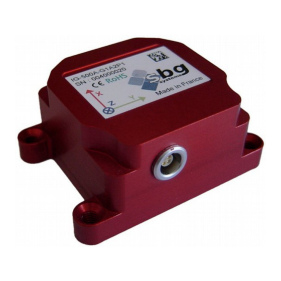
IG-500A sub-miniature AHRS
Sub-miniature AHRS
Document : IG500AUM.12
Revision : 12 - Nov 22, 2013
Covers Firmware V 2.1
SBG Systems
3bis, chemin de la Jonchère
92500 Rueil Malmaison
FRANCE
SBG Systems
IG-500A
User Manual
Email :
support@sbg-systems.com
Phone : +33 1 80 88 45 00
1/62
User Manual
IG500AUM.12
Advertisement
Table of Contents

Subscribe to Our Youtube Channel
Related Manuals for SBG Systems IG-500A


Summary of Contents for SBG Systems IG-500A
- Page 1 IG-500A sub-miniature AHRS User Manual IG-500A Sub-miniature AHRS User Manual Document : IG500AUM.12 Revision : 12 - Nov 22, 2013 Covers Firmware V 2.1 SBG Systems Email : support@sbg-systems.com 3bis, chemin de la Jonchère Phone : +33 1 80 88 45 00...
-
Page 2: Revision History
8 July 2008 Alexis GUINAMARD First version of this document © 2007 – 2013, SBG Systems SAS. All rights reserved. Information in this document is subject to change without notice. Copy or redistribution of this document is forbidden without express authorization of SBG Systems. - Page 3 2.3.9. IMU 500................................. 13 2.4. Heave computation......................14 2.5. Internal Sensors........................14 2.5.1. Inertial and magnetic sensors sampling and filtering..................14 2.6. IG-500A timing and synchronization with other devices............17 2.6.2. Synchronization Output..........................17 2.6.3. Computation and transmission delays......................18 2.7. Specifications........................21 2.7.1. Performance..............................21 2.7.2.
- Page 4 4.1. Driver and software installation...................28 4.2. Provided software and libraries...................28 4.2.1. The sbgCenter............................... 28 4.2.2. Communication with the device........................29 4.2.3. Low level communication with the IG-500A....................30 4.2.4. Matlab and Labview integration........................30 4.3. Getting optimal results......................31 5. IG-500A Outputs........................32 5.1.
- Page 5 IG-500A sub-miniature AHRS User Manual 7.6. Advanced options........................ 52 7.6.1. Power modes..............................52 7.6.2. Miscellaneous..............................52 7.7. Device default settings......................53 8. Electrical and mechanical specifications................54 8.1. Absolute maximum ratings....................54 8.2. Box -B version........................55 8.2.1. Mechanical outline............................55 8.2.2. Device connectors............................56 8.3.
- Page 6 The IG-500A therefore perfectly matches with control, stabilization, motion analysis of robots, machines, as well as human body segments. An OEM version of the IG-500A is proposed to make it very easy to integrate our product in weight and size sensitive applications.
- Page 7 The IG-500 Development Kit is an essential tool that has been designed to provide easy and efficient IG-500A integration. Provided software and libraries will give the opportunity to rapidly develop powerful applications. In addition, it is made very easy to connect the IG-500A to a PC with the provided USB interface.
-
Page 8: Block Diagram
2.2. Extended Kalman filter 2.2.1. Purpose The IG-500A includes a real time Extended Kalman Filter. It delivers to the IG-500A precise tracking of the device’s orientation, as well as sensor information such as gyroscopes bias. This Kalman filter performs data fusion between the three main sensors: Gyroscopes, Accelerometers and Magnetometers, to take full advantage of all collected information: Gyroscopes integration allows calculating orientation very precisely in a short term. -
Page 9: General Purpose
Each motion profile includes parameters relative to magnetic field and other heading observation methods. It's then possible to select different heading sources within a motion profile configuration. The following motion profiles are available by default on the IG-500A. Their characteristics and assumptions are described and special recommendations are also provided if required. - Page 10 IG-500A sub-miniature AHRS User Manual 2.3.2. Airplane Assumptions Comments Description This motion profile is well suited for general aircraft applications that have low to medium dynamics. This motion profile can be used only for fixed wings vehicles of any size.
- Page 11 IG-500A sub-miniature AHRS User Manual 2.3.4. Helicopter Assumptions Comments Description This motion profile is well suited for helicopter applications, as well as many land robots with significant vibration level. Update rate 100Hz Vibrations High vibrations are tolerated. Accelerations Presence of long term accelerations assumed.
- Page 12 IG-500A sub-miniature AHRS User Manual 2.3.6. Marine Assumptions Comments Description This motion profile is dedicated to general marine applications. Update rate 100Hz Vibrations Medium vibrations are tolerated. Accelerations Low long term accelerations. Magnetic field Medium confidence in magnetic field measurement.
- Page 13 IG-500A sub-miniature AHRS User Manual 2.3.8. Human motion Assumptions Comments Description This motion profile is specially designed for high speed rotations seen in human motion applications. It requires the High Performance mode to be enabled Update rate 200Hz Vibrations Non vibrating environment is assumed...
-
Page 14: Internal Sensors
SBG Systems has developed an advanced filter design that ensures no phase and gain errors are generated as long as correct average heave period is provided by user. - Page 15 IG-500A sub-miniature AHRS User Manual 2.5.1.1. Accelerometers Accelerometers outputs are first fed into a hardware one pole low pass filter. This filter ensures anti aliased sampling. Once sampled by a 16 bit SAR (Successive Approximation Register) Analog to Digital Converter, measurements are fed into a 2 stages high efficiency FIR filter. This filter provides the best vibration isolation.
- Page 16 Optimal performance is obtained with a stable ambient temperature. Note: The Kalman filter inside the IG-500A is designed to estimate in real time gyro bias evolutions, but a static gyro bias reset sequence can be made to provide faster bias estimation, and faster Kalman filter stabilization.
- Page 17 2.6.1.1. Synchronization Input The IG-500A accepts a logic input (Sync In) signal to synchronize the IG-500A with an external device, or host clock. Events can be generated on rising, falling edge, or on level change.
- Page 18 IG-500A sub-miniature AHRS User Manual 2.6.3. Computation and transmission delays The following diagram shows what happens when user sets the output divider to 2 (one data frame is send each two loops), and a synchronization output is enabled. This example covers serial devices, but similar considerations can be used on CAN bus devices.
- Page 19 IG-500A sub-miniature AHRS User Manual The following table shows the different computational times required: Output Options Computational latency Computational latency (normal power mode) (High performance power mode) Output mask: Time since reset, 4,2 ms 1.7 ms device status, Euler Angles,...
- Page 20 On the first example, the IG-500A computes orientation with its internal clock, and each time a new computation loop is started, it sends a sync Out pulse. User application can then synchronize itself on the IG-500A by knowing exactly when is measured each sample.
-
Page 21: Specifications
IG-500A sub-miniature AHRS User Manual 2.7. Specifications All specifications are valid in the full temperature range -40°C to 85°C unless otherwise specified. 2.7.1. Performance Parameter Specification Remarks - Conditions Sensing range 360° in all axes, no mounting limitation Solid state sensors Orientation Accuracy ±... - Page 22 IG-500A sub-miniature AHRS User Manual 2.7.2. Internal sensors specifications Accelerometers Remarks - Conditions Measurement range ± 2g ± 5g ± 18g Non-linearity < 0.2% < 0.2% < 0.2% % of full scale Bias at startup ± 2 mg ± 5 mg ±...
-
Page 23: Communication Interfaces
Each output can be enabled or disabled device status... Bit-rate 10 to 1 000 kbps User selectable Contact SBG Systems if bus termination is Bus termination Not included required Table 8: CAN interface specifications SBG Systems 23/62 IG500AUM.12... -
Page 24: Electrical Specifications
IG-500A sub-miniature AHRS User Manual 2.7.4. Electrical specifications Parameter Specification Remarks – Conditions Operating voltage 3.3 to 30V Power consumption 400 mW @ 5.0V Normal performance mode 0 Level: < 0.8 V Input Range : ± 20V Logic Inputs 1 Level: > 2.0V Input Delay: <150 ns... -
Page 25: Optimal Placement
The IG-500A should be placed as far as possible from ferromagnetic materials, particularly those who can be moved independently with respect to the IG-500A. In practice placing the device more than 1 meter away from moving ferromagnetic materials is enough to avoid generating error. - Page 26 Note: This placement requirement is also seen in several motion profiles. 3.1.2.2. User heading When using the User heading source, the IG-500A assumes that the heading provided is consistent with the IG-500A X axis direction. It belongs to user to realign heading value if required. 3.1.3. Accelerations 3.1.3.1. Transient acceleration During transient accelerations, the device is not able to differentiate gravity and other accelerations.
-
Page 27: Environmental Considerations
1 kHz can be easily filtered using simple mechanical dampers. 3.2. Environmental considerations The normal condition to operate the IG-500A is within the industrial range: -40 to +85°C, in a dry and non condensing environment. If the device is operated beyond absolute maximum ratings, expressed in 16, the device may be damaged. -
Page 28: Driver And Software Installation
4.2. Provided software and libraries 4.2.1. The sbgCenter The sbgCenter is a very powerful program suit. It allows deeply analyzing outputs of the IG-500A, by displaying, recording, and exporting a set of data. Graphs can be displayed, as well as a 3D representation of orientation. -
Page 29: Communication With The Device
IG-Devices Serial Protocol Specifications and IG-Devices CAN Protocol Specifications to directly communicate with the device. For even easier integration into existing systems, the IG-500A is able to output an ASCII output. 4.2.2.1. The C libraries sbgCom / sbgCan The IG-500A DK provides an easy access to the device with the libraries sbgCom and sbgCan. - Page 30 IG-500A. 4.2.4.2. Labview integration The sbgLabView library provides a full support of the IG-500A on Labview 8.2. An example using this library is provided for a better understanding of the library. Also note that continuous mode has to be enabled in order to retrieve outputs from the IG-500A.
- Page 31 User Manual 4.3. Getting optimal results The IG-500A is a measuring device, and in order to reach optimal performance, some checks and considerations have to be carefully done. If it is not the case, performance of the device can be rapidly affected.
- Page 32 IG-500A sub-miniature AHRS User Manual 5. IG-500A Outputs The following section describes all IG-500A outputs. Please refer to the IG-Devices Serial Protocol Specifications and IG Devices CAN Protocol Specifications for more information about all outputs such as units. 5.1. Calibrated sensors output The IG-500A includes 14 calibrated sensors: 3 accelerometers, 3 gyroscopes, 3 magnetometers and 5 temperature sensors.
- Page 33 The gyroscopes temperature output is the temperature measured by the three temperature sensors included in the gyroscopes. Note: The temperature sensors inside the IG-500A have a very good repeatability, required for sensor calibration, but only a poor absolute accuracy, especially the gyroscopes internal temperature sensors.
-
Page 34: Other Outputs
Time since last reset This output provides in ms the time elapsed since the last reset of the IG-500A. This time is measured at the beginning of the sampling and calculation loop of the device. - Page 35 User Manual Device Status The IG-500A performs at start-up a sensor Self-Test, as well as some internal initialization checks. This self test inform the user of potential device failure. Some other outputs are updated in real time and inform about the health of the Kalman filter.
-
Page 36: Coordinate Systems
User has to distinguish two coordinate frames when working with an inertial measurement unit, such as the IG-500A. The first coordinate frame is the inertial (or device) coordinate frame, in which values are expressed in this local coordinate frame. This coordinate frame follows the movements of the device. - Page 37 6.1.2.1. Magnetic North vs. true North By default, the IG-500A is aligned on the local magnetic North. It is important to note that this magnetic North is not aligned with the true North. The difference between the real north direction and the magnetic north direction is called declination.
- Page 38 IG-500A sub-miniature AHRS User Manual 6.2. Orientation representation There are several ways to represent the orientation of the device that are provided by the IG-500A. Some are easy to understand, others are very efficient such as quaternion form: 6.2.1. Euler Angles Euler angles are a commonly used representation of spatial orientation.
- Page 39 IG-500A sub-miniature AHRS User Manual Reciprocally: =DCM ⋅V Sensor Earth 6.2.3. Quaternions Quaternions are an extension of complex numbers, as defined here: j⋅q i⋅q k⋅q Where i, j and k are imaginary numbers. Particular quaternions such as ∥Q∥=1 can represent, as DCMs, a complete definition of the 3D orientation, without any singularity.
- Page 40 IG-500A sub-miniature AHRS User Manual 6.2.4. Other useful conversion formulas Some other conversion formulas can be useful for many users, and are listed below: 6.2.4.1. Quaternion to DCM It may be useful to compute a DCM based on the quaternion’s parameters: ...
-
Page 41: Protocol Configuration
IG-500A can do this very deeply. All configurable settings can be saved in the non-volatile memory or not. Thanks to this mechanism, the user can configure his device permanently or temporary depending on his needs. - Page 42 Triggered mode In addition to the basic continuous mode, the IG-500A supports a triggered output mode which offers the possibility to send only newly computed data. It is really suitable with data that are not continuously updated such as GPS fix or barometer data.
- Page 43 IG-500A sub-miniature AHRS User Manual 7.1.1.5. NMEA and ASCII outputs The IG-500A is able to provide an ASCII output sentence. Configuration has to be made through the main IG-Devices Serial protocol. The following message is supported: Message Content $SBG01 Euler angles and orientation accuracy in degrees.
- Page 44 IG-500A sub-miniature AHRS User Manual 7.1.2.2. Frames Identifiers (CAN bus) CAN devices have to be able to adapt to a user CAN bus. It is possible to configure the device to use standard or extended CAN messages ids. In addition, for each CAN message, handled by the device, it's possible to define it's id or even disable it.
- Page 45 Filter DataOutput divider When this divider is set to a value larger than one, the IG-500A will send a new output frame each N loops in order to limit output bandwidth. 7.1.3.2. Available Triggers The following triggers sources can generate outputs. Multiple triggers can be active in the same...
- Page 46 Default configuration is 0. 7.2.2. User Buffer As a User ID complement , the IG-500A includes a 64 bytes buffer reserved for user needs. This buffer can be written, read, and saved to non volatile memory.
- Page 47 IG-500A sub-miniature AHRS User Manual 7.3. Kalman filter configuration The IG-500A Kalman filter can be configured by a set of independent parameters. Theses options provide an easy access to deep sensor behavior configuration. 7.3.1. Motion profiles The IG-500A Kalman filter is configured through the motion profile. Please check section 2.3 Motion profiles for more information about motion profiles.
- Page 48 IG-500A sub-miniature AHRS User Manual 7.3.2. Select heading source In conjunction with the motion profile, a good heading source has to be configured for proper operation. Example application Heading Source Constraints for optimal use Static startup assumption may improve Vertical gyroscope •...
- Page 49 7.4. Coordinate frames transformation 7.4.1. Pre-Rotations Sometimes, it is hard to align the device local axes with the object on which it is installed. IG-500A devices have an easy way to manage these kinds of problems. Those three functions allow user to realign the local coordinate frame with the object axes.
- Page 50 When this function is called, orientation is reset to a zero in all angles: roll pitch and yaw, whatever is your orientation. If the screen on which you want to display the IG-500A orientation is not vertical but is fixed on the ceiling or the ground for example, you can simply point the device to the screen, and its orientation will be referenced with respect to the screen.
-
Page 51: Calibration Procedures
Once the calibration is performed, user can save the results to the non-volatile flash memory. Note 1: When using magnetometers for heading, you have to calibrate the magnetometers carefully after installing the IG-500A into your application. If the magnetometers calibration is incorrect, all measurements including roll and pitch could be greatly impacted. -
Page 52: Advanced Options
7.6.1. Power modes 7.6.1.1. IMU power mode The IG-500A now supports two power modes: • Normal mode, which is the default one and is convenient with most applications. • High Performance mode which allows Heave computation and provides ultra low computational latency. -
Page 53: Device Default Settings
IG-500A sub-miniature AHRS User Manual 7.7. Device default settings Here are summarized the default parameters for the IG-500A: Parameter Default value Serial protocol Protocol mode 115 200 bauds Output mode big-endian, float CAN protocol Bit rate 1 000 Kbit/s Propagation segment... -
Page 54: Electrical And Mechanical Specifications
IG-500A sub-miniature AHRS User Manual 8. Electrical and mechanical specifications 8.1. Absolute maximum ratings Stresses above those listed under the Absolute Maximum Ratings may cause permanent damage to the device. This is a stress rating only; functional operation of the device at these or any other conditions above those indicated in the operational section of this specification is not implied. - Page 55 IG-500A sub-miniature AHRS User Manual 8.2. Box -B version 8.2.1. Mechanical outline SBG Systems 55/62 IG500AUM.12...
-
Page 56: Device Connectors
IG-500A sub-miniature AHRS User Manual 8.2.2. Device connectors All signal lines are expressed from IG-500A side. For example, Tx line is IG-500A Tx so it's an output. 8.2.2.1. Main connector The main connector is a Lemo receptacle which mates with a four wire Lemo connector, ref . - Page 57 IG-500A sub-miniature AHRS User Manual 8.3. Box -S version 8.3.1. Mechanical outline SBG Systems 57/62 IG500AUM.12...
- Page 58 IG-500A sub-miniature AHRS User Manual 8.3.2. Box device connector All signal lines are expressed from IG-500A side. For example, Tx line is IG-500A Tx so it's an output. 8.3.2.1. Main connector The Main connectors is a Lemo receptacle which mates with a seven way Lemo connector, ref FGG.0B.307.CLAD35.
-
Page 59: Warranty And Support
Our goal is to provide the best experience to our customers. If you have any question, comment or problem with the use of your IG-500A, we would be glad to help you, so please feel free to contact us. Please do not forget to mention your IG-500A Device ID (written on your IG-500A’s label). -
Page 60: Appendix: Accessories
IG-500A sub-miniature AHRS User Manual 10. Appendix: Accessories 10.1. UsbToUart interface For RS-232 and RS-422 products, the development kit provides the UsbToUart interface. It features the following characteristics: 64x42x20 mm box • 3 meters long cable • USB 1.1 or higher compatible •... -
Page 61: Power Adapter
10.2.2. CAN to USB2CAN cable The CAN development kit also includes a cable required to connect the IG-500A to the USB2CAN interface. It has the following features: 3 meters long shielded cable with twisted pairs for data • transmission. -
Page 62: Other Cables
Those cables provide rapid access to the IG-500A without having to manage the Lemo plug soldering. They consist on a 3m cable, connected on one side to the IG-500A Lemo plug, and on the other side to a 1.25mm Molex connector.
Need help?
Do you have a question about the IG-500A and is the answer not in the manual?
Questions and answers