Table of Contents
Advertisement
Quick Links
Advertisement
Table of Contents

Related Manuals for SBG Systems Apogee Surface Series


Summary of Contents for SBG Systems Apogee Surface Series
- Page 1 Apogee Surface series Ultimate Accuracy MEMS Inertial Sensors User Manual Document APOGEEHM.1.5 Support EMEA Revision 1.5 - Jul 2, 2020 support@sbg-systems.com Covers Hardware Apogee V2 and above +33 1 80 88 43 70 Americas support@sbg-systems.com +1 (657) 549-5807...
- Page 2 Mar 6, 2015 Raphaël Siryani First preliminary version © 2007 – 2020, SBG Systems SAS. All rights reserved. Information in this document is subject to change without notice. Copy or redistribution of this document is forbidden without express authorization of SBG Systems.
-
Page 3: Table Of Contents
Apogee Series – Hardware Manual APOGEEHM.1.5 Index Terminology................................6 1. Introduction................................ 7 1.1. Apogee Overview............................8 2. Performance specifications..........................9 2.1. Inertial measurement unit........................9 2.1.1. Accelerometers..................................9 2.1.2. Gyroscopes....................................9 2.2. Aiding sensors............................10 2.2.1. Apogee-D internal GNSS receiver............................10 2.2.2. - Page 4 Apogee Series – Hardware Manual APOGEEHM.1.5 4.3. Main connector............................23 4.3.1. Connector specifications............................... 23 4.3.2. Connector pin out................................. 24 4.3.3. Electrical specifications (V1 hardware)..........................25 4.3.4. Electrical specifications (V2 hardware)..........................26 4.4. External aiding connector........................27 4.4.1. Connector specifications............................... 27 4.4.2.
- Page 5 Apogee Series – Hardware Manual APOGEEHM.1.5 7.3. Associated Software..........................44 7.3.1. SW-AEK-SDK (Software Development Kit)........................... 44 7.3.2. SW-QINERTIA-PRO (GNSS/INS Post Processing Software)....................44 7.4. Cables............................... 45 7.4.1. CA-AEK-PWR-PSU-1.5M................................. 45 7.4.2. CA-AEK-PWR-3M................................... 45 7.4.3. CA-AEK-MAIN-ETH-2.5M..............................45 7.4.4. CA-AEK-MAIN-RS232-3M..............................46 7.4.5. CA-AEK-MAIN-RS422-3M..............................47 7.4.6.
-
Page 6: Terminology
Apogee Series – Hardware Manual APOGEEHM.1.5 Terminology ADC: Analog to Digital Converter AHRS: Attitude and Heading Reference System CAN (Bus): Controller Area Network DHCP: Dynamic Host Configuration Protocol DVL: Doppler Velocity Log EKF: Extended Kalman Filter EEPROM: Electrically-Erasable Programmable Read-Only Memory FIR: Finite Impulse Response (filter) FTP: File Transfer Protocol FS: Full Scale... -
Page 7: Introduction
Apogee Series – Hardware Manual APOGEEHM.1.5 1. Introduction Apogee series is a line of very high performance, MEMS based Inertial Systems which achieve exceptional orientation and navigation performance in a compact and affordable package. It includes an Inertial Measurement Unit (IMU) and runs an on-board enhanced Extended Kalman Filter (EKF). -
Page 8: Apogee Overview
Apogee Series – Hardware Manual APOGEEHM.1.5 1.1. Apogee Overview The following diagram shows the basic organization of an Apogee. On the Apogee-A and E versions, this block diagram is slightly simplified as there is no embedded GNSS. DATA FUSION GNSS Data logger 3 Axis ETHERNET... -
Page 9: Performance Specifications
Apogee Series – Hardware Manual APOGEEHM.1.5 2. Performance specifications 2.1. Inertial measurement unit As an IMU is the main component of an inertial navigation system, the Apogee IMU has been carefully designed to take full advantage and performance of MEMS technology. 2.1.1. -
Page 10: Aiding Sensors
Apogee Series – Hardware Manual APOGEEHM.1.5 2.2. Aiding sensors Many different aiding sensors can be used to aid the Apogee INS. 2.2.1. Apogee-D internal GNSS receiver The Apogee-D embed a very high end, survey grade GNSS receiver with dual antenna heading capability. It features L1/L2/L5 and L-Band signals tracking and uses GPS, GLONASS, BEIDOU and GALILEO constellations to provide very accurate and reliable measurements even in harsh environments. -
Page 11: External Aiding Sensors
Apogee Series – Hardware Manual APOGEEHM.1.5 2.2.2. External aiding sensors The Apogee-A accepts a single external GNSS receiver connection to improve orientation performance. The Apogee-E, N and D models accepts up to two external GNSS receivers to provide navigation data and improve orientation performance In addition, a DVL or an odometer can be connected on Apogee-E/N/D as velocity aiding inputs. -
Page 12: Heave Performance
Apogee Series – Hardware Manual APOGEEHM.1.5 2.3.2.1. Heave performance Real Time Heave Delayed Heave (ShipMotionHP) Remark Range 50 meters 50 meters Automatic adjustment to every sea conditions Period 0 to 20 s 0 to 40 s Accuracy 5 cm or 5% 2 cm or 2 % Whichever is greater;... -
Page 13: Mechanical Specifications
Apogee Series – Hardware Manual APOGEEHM.1.5 3. Mechanical specifications 3.1. Overview The Apogee enclosure is composed of two anodized aluminum parts, one for the cover and one for the base plate. The device uses high quality alloys and connectors to offer a full IP-68 enclosure and a good resistance to harsh environments. -
Page 14: Device Mechanical Alignment
Apogee Series – Hardware Manual APOGEEHM.1.5 3.1.2. Device mechanical alignment For best measurement accuracy, a good mechanical alignment is required. During manufacturing, the Apogee measurement frame has been carefully aligned to 0.02° with the base plate for roll, pitch and yaw angles. -
Page 15: Apogee-A / E Mechanical Outline
Apogee Series – Hardware Manual APOGEEHM.1.5 3.2. Apogee-A / E mechanical outline All dimensions are in mm. 3.2.1. Front view 3.2.2. Right view 15/53... -
Page 16: Top View
Apogee Series – Hardware Manual APOGEEHM.1.5 3.2.3. Top view 16/53... -
Page 17: Bottom View
Apogee Series – Hardware Manual APOGEEHM.1.5 3.2.4. Bottom view 100 ±0,30 91 ±0,10 77,70 4 H8 11,30 4 H8 4 HOLES 4,50 17/53... -
Page 18: Apogee-D Mechanical Outline
Apogee Series – Hardware Manual APOGEEHM.1.5 3.3. Apogee-D mechanical outline All dimensions are in mm. 3.3.1. Front view 14,50 14,50 3.3.2. Right view 18/53... -
Page 19: Top View
Apogee Series – Hardware Manual APOGEEHM.1.5 3.3.3. Top view 19/53... -
Page 20: Bottom View
Apogee Series – Hardware Manual APOGEEHM.1.5 3.3.4. Bottom View 100 ±0,30 91 ±0,10 77,70 4 H8 11,30 4 H8 4 HOLES 4,50 20/53... -
Page 21: Electrical Specifications
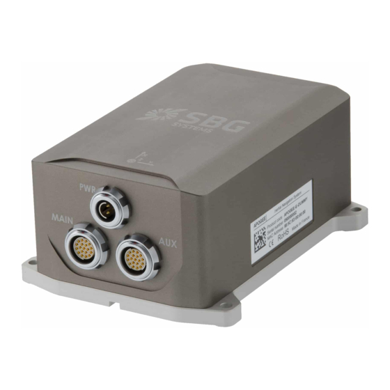
SBG Systems has selected high quality connectors designed for harsh environments. They offer an IP -68 protection when the plug is properly mounted. Note: The Apogee cables are not all designed to offer an IP-68 protection. Contact SBG Systems to get further support about IP-68 protection. -
Page 22: Power Supply Connector
Apogee Series – Hardware Manual APOGEEHM.1.5 4.2. Power supply connector The Apogee can be powered by a DC voltage from 9 to 36 Volts. For best robustness and to reduce power consumption, the internal power module is a high efficiency isolated DC/DC converter. Apply a constant power supply to VIN+ and VIN- pins. -
Page 23: Electrical Specifications
Apogee Series – Hardware Manual APOGEEHM.1.5 4.2.3. Electrical specifications Recommended electrical specifications from -40°C to 71°C. Parameter Min. Typ. Max. Units Conditions Operating voltage Apogee-A and E versions Power consumption Apogee-D version Allowable Input Voltage Ripple mV p-p Turn on threshold Under voltage lock out Turn off threshold VIN+ to Mechanical Ground... -
Page 24: Connector Pin Out
Apogee Series – Hardware Manual APOGEEHM.1.5 S-104-A092-130 (Core Series version) ● 4.3.2. Connector pin out Connector's pin out is sorted by function rather than pin numbering. Pin # Name Description Shield Shield Connected to the mechanical ground Connected to the main connector electrical ground Connected to the main connector electrical ground Connected to the main connector electrical ground RS-232/RS-422... -
Page 25: Electrical Specifications (V1 Hardware)
Apogee Series – Hardware Manual APOGEEHM.1.5 4.3.3. Electrical specifications (V1 hardware) Recommended electrical specifications from -40°C to 71°C. All signals are referenced to GND_MAIN. Pins #3, #4 and #7 are internally connected. Parameter Conditions Min. Typ. Max. Units RS-232/RS-422 Input Voltage Range Threshold Low Input Threshold Threshold High... -
Page 26: Electrical Specifications (V2 Hardware)
Apogee Series – Hardware Manual APOGEEHM.1.5 4.3.4. Electrical specifications (V2 hardware) Recommended electrical specifications from -40°C to 71°C. All signals are referenced to GND_MAIN. Pins #3, #4 and #7 are internally connected. Parameter Conditions Min. Typ. Max. Units RS-232/RS-422 Input Voltage Range Threshold Low Input Threshold Threshold High... -
Page 27: External Aiding Connector
Apogee Series – Hardware Manual APOGEEHM.1.5 4.4. External aiding connector The external aiding connector is mainly used to connect aiding equipment to the Apogee. It features the following connections: Up to two RS-232 or RS-422 ports that support full-duplex operations ●... -
Page 28: Electrical Specifications
Apogee Series – Hardware Manual APOGEEHM.1.5 Pin # Name Description Port C – RS-422 – Tx+ Port C serial output RS-422 Sync In D Port D input synchronization Port D – RS-232/RS-422 – Rx+ Port D serial input RS-232/RS-422 Port D – RS-422 – Rx- Port D serial input RS-422 Sync In E Port E input synchronization / Odometer B... -
Page 29: Gps Antenna Connectors
Apogee Series – Hardware Manual APOGEEHM.1.5 4.5. GPS antenna connectors To connect external GPS antennas, the Apogee D version includes two IP-68 TNC connectors. Each Apogee is provided with dust caps to seal the TNC connector offering an IP-68 protection. The internal GNSS receiver only supports active GPS antennas. -
Page 30: Electrical Specifications
Don't forget to also check the GPS antenna LNA power requirements such as input voltage (must accepts 5 VDC) and input current (must be below 200 mA per antenna). SBG Systems has selected some high quality GPS antennas for different applications. Please refer to the section 7.5 GPS accessories to get more details on available antennas. -
Page 31: Typical Wiring
Apogee Series – Hardware Manual APOGEEHM.1.5 4.6. Typical wiring In this section, we briefly describe a few recommended wiring diagrams. 4.6.1. Power supply connection Concerning power supply, we recommend shielded cable, with at least AWG 24 wires. Apogee Power Supply Power Connector +9 to 36V DC SHIELD... -
Page 32: Main Interface Connection On Rs-422
Apogee Series – Hardware Manual APOGEEHM.1.5 4.6.3. Main interface connection on RS-422 Below is shown the main interface (Port A) connection, using a full duplex RS-422 connection. The recommended cable is a shielded twisted pairs AWG26 cable. Note the termination resistors (Usually 120 ohms) that can optionally be placed on receiver side to avoid communication errors in long distance communications. -
Page 33: Gnss Connection In Rs-232 Mode
Apogee Series – Hardware Manual APOGEEHM.1.5 4.6.5. GNSS connection in RS-232 mode For this typical connection, a shielded AWG 26 cable should be used. Depending on PPS signal strength, we do not recommend this cable to measure more than a few meters. For long distance, PPS signal and GPS NMEA signals should be separated in two cables for better noise immunity. -
Page 34: Triggering External Devices With The Sync Out
Apogee Series – Hardware Manual APOGEEHM.1.5 4.6.7. Triggering external devices with the sync Out Consider a camera that must take a picture when an event is provided on Event Out pin. Event Out and Sync Out are “open drain” outputs, which means a pull up resistor must be used on receiver side, as shown on the diagram. -
Page 35: Typical Connection Topologies
Apogee Series – Hardware Manual APOGEEHM.1.5 4.7. Typical connection topologies The following use cases are presented to quickly show how to connect the Apogee to various external materials in different applications. 4.7.1. Apogee-D in advanced automotive application Here we present an advanced use case where the Apogee-D sensor is used in a land survey application. The Apogee configuration is the following: On the aiding/input side: ●... -
Page 36: Apogee-E In Marine Application
Apogee Series – Hardware Manual APOGEEHM.1.5 4.7.2. Apogee-E in marine application In the next application example, the Apogee is used for both vessel display and monitoring, as well as ship motion sensor for several third party equipment. Connections are made easy using Ethernet interface when available with external devices. GNSS DISPLAY ETH 0 :... -
Page 37: Interfaces Specifications
Note 2: For more details about the Ethernet interface capabilities, please read the Ellipse Ekinox and Apogee Technical Reference Manual. Browser Compatibility: SBG Systems recommend using latest version of Chrome, Safari or FireFox web browser. Due to Internet Explorer limitations, only versions 9 and above are supported. -
Page 38: Serial Interfaces
Apogee Series – Hardware Manual APOGEEHM.1.5 5.3. Serial interfaces Physical serial interfaces are designated as Port A, B, C, D and E and have the following common characteristics: 4800 to 921 600bps operation (Default set to 115200) ● RS-232 or RS-422 modes, configured by software ●... -
Page 39: Connections Mapping
Apogee Series – Hardware Manual APOGEEHM.1.5 5.4.1. Connections Mapping You will find below the available connections configuration for aiding inputs. The Apogee A, E and D share roughly the same mapping but there are some specificity due to the embedded GNSS receiver present in the Apogee D. -
Page 40: Internal Datalogger
Apogee Series – Hardware Manual APOGEEHM.1.5 5.5. Internal Datalogger The Apogee includes an internal datalogger capable of storing all data at 200Hz for 48 hours. The internal datalogger is composed of a high speed memory buffer and an 8 GB flash storage. To allow high bandwidth and to reduce power consumption, the memory buffer is saved to the flash storage ten times per second. -
Page 41: Important Notices
The Apogee will not require any specific maintenance when properly used. In the case you observe sub- optimal performance, please contact SBG Systems support. Nevertheless, if you would like to maintain your sensor performance to the highest level, SBG Systems can provide a maintenance service with regularly planned checkups and calibrations. -
Page 42: Support
(2) years from the date of shipment. In the event that such a defect becomes obvious during the stipulated warranty period, SBG Systems will undertake, at its sole discretion, either to repair the defective product, bearing the cost of all parts and labor, or to replace it with an identical product. -
Page 43: Appendix A: Ordering Codes And Accessories
Apogee Series – Hardware Manual APOGEEHM.1.5 7. Appendix A: Ordering codes and Accessories 7.1. Apogee variants The following Apogee variants are available to order. Please contact your sales representative for more information. Apogee Variant APOGEE-A | Marine MRU APOGEE-E | Marine INS APOGEE-D | Marine INS - GNSS APOGEE-D | Marine INS - GNSS RTK APOGEE-E | Land Air INS... -
Page 44: Associated Software
Apogee Series – Hardware Manual APOGEEHM.1.5 7.3. Associated Software 7.3.1. SW-AEK-SDK (Software Development Kit) The Apogee Software Development Kit is very helpful to configure, playback recorded logs, export data to text files or third party software and even develop custom code for the Apogee. It contains the following items: sbgCenter analysis software ●... -
Page 45: Cables
Apogee Series – Hardware Manual APOGEEHM.1.5 7.4. Cables 7.4.1. CA-AEK-PWR-PSU-1.5M This cable is an international AC/DC adapter to power up the Apogee or the SplitBox. 110 / 250 V input with UK, US and EU plugs. ● 12V output ● No IP rating Figure 7.3 : AC / DC power ●... -
Page 46: Ca-Aek-Main-Rs232-3M
Apogee Series – Hardware Manual APOGEEHM.1.5 7.4.4. CA-AEK-MAIN-RS232-3M This cable is designed to mate with the MAIN connector and provides RS-232 communication with PORT A as well as other MAIN connector pins access. 1 x Fischer Core Series S-104-A092-130 ● 1 open end ●... -
Page 47: Ca-Aek-Main-Rs422-3M
Apogee Series – Hardware Manual APOGEEHM.1.5 7.4.5. CA-AEK-MAIN-RS422-3M This cable is designed to mate with the MAIN connector and provides RS-422 communication with PORT A as well as other MAIN connector pins access. 1 x Fischer Core Series S-104-A092-130 ● 1 open end ●... -
Page 48: Ca-Aek-Aux-3M
Apogee Series – Hardware Manual APOGEEHM.1.5 7.4.6. CA-AEK-AUX-3M This cable is designed to mate with the AUX connector and provides access to all AUX connector pins. 1 x Fischer Core Series S-104-A092-230 ● 1 open end ● IP-68 rating ● 3 m AWG26 shielded cable with twisted pairs ●... -
Page 49: Ca-Aek-Split-Main-0.5M
Apogee Series – Hardware Manual APOGEEHM.1.5 7.4.7. CA-AEK-SPLIT-MAIN-0.5M This cable provides a robust and easy access interfaces available on the Apogee MAIN connector using standard plugs. Figure 7.9: CA-AEK-SPLIT-MAIN-0.5M – Lengths not to scale The cable has following characteristics: 1 x Fischer Core Series S-104-A092-130 that connects on MAIN connector ●... -
Page 50: Ca-Aek-Split-Main2-0.5M
Apogee Series – Hardware Manual APOGEEHM.1.5 7.4.8. CA-AEK-SPLIT-MAIN2-0.5M This cable provides a robust and easy access interfaces available on the Apogee MAIN connector using standard plugs. Figure 7.10: CA-AEK-SPLIT-MAIN2-0.5M – Lengths not to scale The cable has following characteristics: 1 x Fischer Core Series S-104-A092-130 that connects on MAIN connector ●... -
Page 51: Ca-Aek-Split-Aux-0.5M
Apogee Series – Hardware Manual APOGEEHM.1.5 7.4.9. CA-AEK-SPLIT-AUX-0.5M This cable provides a robust and easy access serial ports available on the Apogee connector using standard DB-9 plugs. Figure 7.11: CA-AEK-SPLIT-AUX-0.5M – Lengths not to scale The cable has following characteristics: 1 x Fischer Core Series S-104-A092-130 that connects on MAIN connector ●... -
Page 52: Gps Accessories
Apogee Series – Hardware Manual APOGEEHM.1.5 7.5. GPS accessories 7.5.1. GNSS antennas The following GPS antennas are recommended for Apogee-D operations: Product code Description Photo ANT-SEP-POLANT-MC Survey grade, geodetic antenna L1 / L2 / L5, L-Band GPS, GLONASS, GALILEO, Beidou Pole Mount –... -
Page 53: Appendix B: Packaging, Labeling
8. APPENDIX B: Packaging, labeling 8.1. Board Identification SBG Systems manufacturing process is based on EN-9100 system with individual and full traceability of every component and operation. Each device is identified by a unique serial number which is used to trace all operations during the product lifetime such as manufacturing, calibration, tests and repairs.
Need help?
Do you have a question about the Apogee Surface Series and is the answer not in the manual?
Questions and answers