Table of Contents
Advertisement
Quick Links
Advertisement
Table of Contents

Related Manuals for LARTET DN-107NN Series


Summary of Contents for LARTET DN-107NN Series
- Page 1 OPERATION MANUAL OF THE DN-107NN DISPLAYS 1227K34A...
-
Page 2: Table Of Contents
INDEX INTRODUCTION ........................3 1. GENERAL CHARACTERISTICS ....................4 1.1. Electrical characteristics of the displays ................4 1.1.1. Electrical characteristics of the dn-107 displays ............4 1.2. Dimensions and fixation of the displays ................5 1.2.1. Dimensions of DN-107/3 displays ................5 1.1.1. -
Page 3: Introduction
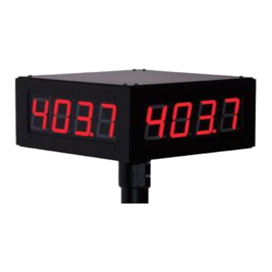
INTRODUCTION The numerical displays of the DN-107NN series are industrial displays that are controlled by the PROFINET protocol. The selection of the parameters and the communication protocol is done by means of a pair of pushbuttons with an easy-to-program code system. -
Page 4: General Characteristics
1. GENERAL CHARACTERISTICS 1.1. Electrical characteristics of the displays 1.1.1. Electrical characteristics of the dn-107 displays Supply voltage ........100 to 240 VAC 50/60Hz. Option 24VDC. Consumption ........See section 2.2 Display ........... 7 segments of 57mm height + decimal point.............. -
Page 5: Dimensions And Fixation Of The Displays
1.2. Dimensions and fixation of the displays 1.2.1. Dimensions of DN-107/3 displays All measurements are in millimeters 1.1.1. Dimensions of DN-107/4 displays All measurements are in millimeters 1227K34A... -
Page 6: Fixing Dn-107 Displays
1.2.2. Fixing DN-107 displays Fixing plate 150/400/600 All measurements are in millimeters... -
Page 7: Installation
2. INSTALLATION The installation of the DN-107NN is not particularly delicate, but some important considerations must be considered. They should not be anchored in places subject to vibration, nor in places that generally exceed the limits specified in the characteristics of the display, both in temperature and humidity. The degree of protection of the DN-107NN displays is IP41, which means that it is protected against the penetration of foreign solid objects of a diameter greater than 1 mm, and against the vertical fall of water droplets. -
Page 8: Profinet Line Connection
2.2. Profinet line connection The connection of the Profinet line in the DN-107/NN displays is carried out by means of the RJ-45 connector located on the inside of the equipment. To access the inside, we will open the top cover of the visualizer. The display incorporates a module with 2 Profinet connectors. -
Page 9: Operation
3. OPERATION 3.1. Initial commissioning Before connecting the visualizer to the network, we must make sure that all connections have been made correctly and that the visualizer is firmly placed. Each time we connect the visualizer to the Power Network, an initial Reset occurs with a test of all the segments that make up the visualizer. -
Page 10: Access To Parameter Settings
4.2.1 Access to parameter settings To enter the sequence of modifying parameters, you must press and hold, the forward key "*" for three seconds. After this time, the first parameter is displayed. From this moment there are two options: 1- Modify the value of the parameter. •... -
Page 11: Access To Parameter Settings
4.2.2 Access to parameter settings 4.2.2.1 Parameter 1: Numeric data type Allows you to select whether to work with numeric values in text format (ASCII) or with Float or Word data types (with or without sign) Parameter Type Numerical range Float -2147483648 to 2147483647 UFloat... - Page 12 4.2.2.4 Parameter 4: Parameters B, C, D, E (Color option) The color option allows you to automatically modify the color of the digits according to the current value. The possible colors are: Red, Green, and Yellow. To be able to manage the color, 2 internal bits (r1 and r2) are used that are activated depending on the value of the visualizer.
- Page 13 4.2.2.5 Parameters nr, r1, r2, r3 (Color option) To define the color, the combination of the 2 internal bits (r1 and r2) is used. The following parameters are used to define colors. Color if no internal bit is enabled. To change the color, press the * key.
-
Page 14: Protocol And Operation Of Work
5. PROTOCOL AND OPERATION OF WORK This section will deal with the PROFINET protocol, as well as communication with the visualizers through this protocol. The numerical value notation used in this manual is as follows: • When we treat a hexadecimal number, the number will be written followed by "h". •... -
Page 15: Profinet Protocol
5.1 PROFINET Protocol This manual will describe the procedure for setting up and commissioning the visualizer with the Siemens TIA Portal V13 tool. If you use third-party software, you should consult its documentation to perform the process described here. 5.1.1 Before the configuration Because each Profinet device is based on DNS (Domain Name System) and the naming conventions for networked computers, it is imperative to assign an identifier name to the visualizer (DeviceName). -
Page 16: Downloading The Gsd File
5.1.2 Downloading the GSD file On our website, on the product page corresponding to Profinet numeric displays you can find the GSD file that allows you to configure the DN-109 series (Compatible for DN-107), DN- 119, DN-129, DN-189 for any number of digits either single/double-sided or with the color option. The file format is as follows: GSDML-V2.31-XXXxxx-XXXXXXX-DN1x9-XXXXXXXX.xml Once downloaded we can proceed to configure the display with the corresponding... - Page 17 We mark our configuration project and press OK. Select the "Set Communication" option and a window will open that will allow us to modify the communication parameters. Fig. 3 Set communication parameters Modify only the data fields derived from the discontinuous rectangles, as the modification of any other field can cause the display to malfunction.
- Page 18 As a final step, the firmware of the visualizer must be updated with the new parameters, for this we will select the option "Update Device". Fig. 5 Update Display FW The IP address that our viewers have configured from the factory is 10.30.90.10. If it is a new computer, this address must be entered in the data field.
-
Page 19: Installing The Display In Tia Portal V13
5.1.4 Installing the display in TIA Portal V13 This section indicates the steps for the integration of the visualizer into the Profinet network. Install the GSD/s of the Displays In TIA Portal V13, click on the menu bar, the "Options" button and select "Manage device description files"... - Page 20 2. Define the Profinet network between displays and PLC’s Connect the displays to the PLC, joining with the Ethernet cable connection, the PLC port with the display ports. Fig. 9 Define the connection of the displays with the PLC Select each of the modules of the visualizations included in the project, and assign them the IP (1), which they will have in the Profinet network.
- Page 21 To assign the range of input/output addresses of the PLC with the display, drag "Module" to the address fields of slot 1 of the module and set the input and output start address to define the range of working addresses. In the numerical displays, a range of 20 output directions will be reserved in the PLC.
-
Page 22: Work Operation
5.2 Work operation As mentioned above, this viewer can work with numeric and text data types (ASCII). If you work in ASCII there are control commands available that allow you to put a data in flicker and change the color of the digit in visualizers with this option. We will detail how it is configured and operated in each of the working modes. - Page 23 2. Sending numeric values over the Profinet network The maximum data block will be 6 bytes if we work with the Float type, or we will use B0 and B1 if we work with the Word type. The structure of the plot is as follows: %QBx %QBx+1 %QBx+2...
- Page 24 5.2.2 ASCII data type In this mode the numeric value will be sent in ASCII code. An advantage of this mode is that it allows you to send control commands, to intermittency a certain value, as well as select the color of the digits in the displays with color option.
- Page 25 Starting flickering characters (must be indicated before the first blinking character) End of characters in flicker (must be indicated after the last character in blink) Displays with color option Digits in red Digits in green Digits in Yellow Example: The following table shows some examples combining numeric values in ASCII format and control commands (assuming the range of addresses defined in Fig.
- Page 26 Let's see an example, for the programming of a simple traffic light, where the following conditions are specified: Values ≤250 Digits in Green 250<Values ≤ 500 Digits in Yellow Values>500 Digits in Red No delay times or hysteresis are established. One of the possible parameter configurations would be the following: Values ≤250 250<Values ≤...
- Page 27 Severo Ochoa, 80 Industrial Estate Font del Radium 08403 Granollers As the builder of the equipment of the LARTET brand: DN-107NN in all its versions. We declare under our sole responsibility that the aforementioned product complies with the following European directives: Directive: LVD 2006/95/CEE Low Voltage Directive.
Need help?
Do you have a question about the DN-107NN Series and is the answer not in the manual?
Questions and answers