
Related Manuals for JetBlack EURUSIII HVLS


Summary of Contents for JetBlack EURUSIII HVLS
- Page 1 EURUSIII HVLS FAN INSTALL & USER MANUAL NZ Distributor of KaLe Environmental Technology (Shanghai) Corp.
-
Page 2: Table Of Contents
Table of Contents HVLS Fans ................................2 Safety Instructions .............................. 2 Safety Gear ................................3 What is in the crates ............................3 Packing List ................................4 Equipment & Tools needed ......................... 4 Fan Diagram & Control Panel........................6 Preparing the Work Site ..........................6 Install Appendix .............................. -
Page 3: Hvls Fans
HVLS Fans These HVLS Fans have multiple uses including cooling, ventilation and destratification. They should be installed according to the customer requirements and as specified by the technical team at Jet Black Fan Systems. When in doubt our team are happy to assist – see contact information for details. Safety Instructions Read the instructions before operation of the equipment and store in safe place for the future use. -
Page 4: Safety Gear
CAUTIONS a. Guy cables must be installed as per the instructions provided in this manual, failure to do so may result in damage or injury and will void the product warranty. b. Do not bend the fan blades when installing or servicing the fan. c. -
Page 5: Packing List
Packing List Below is the list of items supplied with the Eurus HVLS ceiling fan. Note sizes of bolts may vary slightly on different models. Item Description Extension / Downrods (QTY depending on customer site requirements) Fan Blades (With Wingtips) Threaded Rods Fan Controller Motor... - Page 6 • It is recommended that a work zone be clearly marked below the fan installation location by use of safety cones and warning tape to alert persons entering the zone to be vigilant and cautious of potential accidental falling items or risk of EWP injury. Hardware to purchase: Description 1 tonne rated eyebolt –...
-
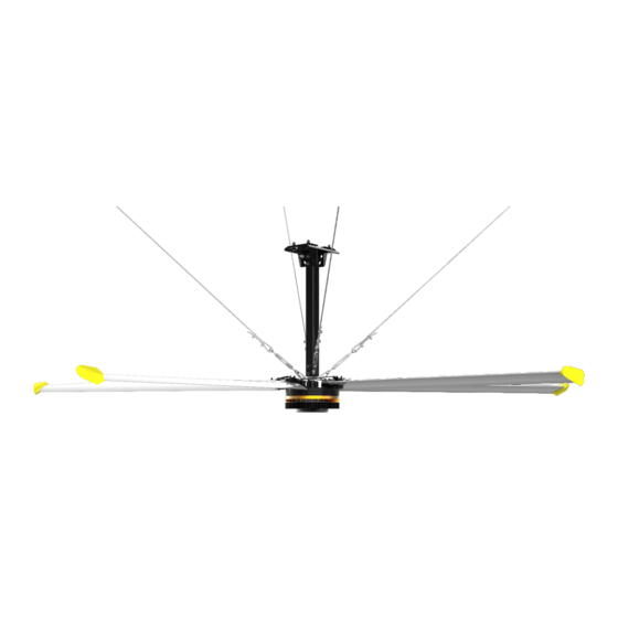
Page 7: Fan Diagram & Control Panel
Fan Diagram & Control Panel See separate manual for touch screen controller if applicable Preparing the Work Site IMPORTANT NOTE: Mount the fan only to a structural element such as an I-beam, square tubing, concrete beam, or other load bearing structure. If large fan is being installed into a lightweight or timber structure it is recommended to have the structure checked by a structural engineer. - Page 8 50 x 50 Square tube install a. If using a square tubing arrangement it is recommended to have this advised by a structural engineer b. Consult a structural engineer to ensure that the structural beams, tubes/plates are rated to uphold the respective fan weights. c.
-
Page 9: Install Appendix
Install Appendix Fan System Layout Note it is best to connect to switchboard on a separate circuit, to ensure nothing else interferes with the fan. It is possible however to connect to a power point if necessary. It is installer responsibility to ensure all cable is appropriately installed as per NZ electrical standards. - Page 10 1. Preparing the Fan Motor Assembly 1.1 Insert the motor wire through the down rod and carefully pull it to leave minimum slack. 1.2 Put the Black Metal Ring over the motor – this sits here until it is installed at step 5 1.3 Install the Down rod on the motor with the provided M16 X 25mm hardware.
- Page 11 The mounting details shown in this section is for I-Beam only. See “preparing the worksite” for other mounting options. 3. Fan Installation - 3.1 Lift the fan motor assembly completed in step 1.2 to the ceiling. 3.2 Install the fan motor assembly to the mounting assembly to the using M16 x 140mm hardware.
- Page 12 4. Installing Turnbuckles and Guy Cables NOTE: Guy cables are intended to provide stability to the fan system during operation and as seismic restraints. Guy cables must be installed as per the instructions in this manual; failure to do so may result in damage or injury and will void the product warranty.
- Page 13 Wire Rope Clip Below is a diagram showing proper clip installation, it is imperative that you install the saddle on the live end of the wire rope. 4.3 Connect the supplied Turnbuckles and Guy Cable loop-1 to the eyes of the Slip Rod as shown in the below figure.
- Page 14 4.5 Attaching Guy Cable Loop 2: Insert wire thimble into the 5/16” eye bolt and route the second end of the guy cable through the wire rope clips and wire thimble to make second Loop. Refer to Step 4.1 for detailed instructions of Guy Wire Loop.
-
Page 15: Electrical Information
Black (no longer silver) metal ring NOTES: • Ensure that all the M12 hardware is installed with the nuts on top of the connecting arms as shown in the figure. • The fan blades should be installed alternatively to balance the load on the guy cables. - Page 16 Diameter 4.9m 5.5m 6.1m 7.3m Weight 106KG 114KG 120KG 135KG Input Voltage 220-240V / 220-240V / 1P 220-240V / 1P 220-240V / 1P KW input Full Load Current 3.0A 3.6A 4.0A 5.0A Noise Level 37.8dB 37.8dB 37.8dB 37.8dB Max speed 75RPM 70RPM 62RPM...
-
Page 17: Maintenance
5. After the fan starts, adjust speed knob to get the appropriate speed and best effect Shut-down: Stop device by turning the power switch from RUN to position STOP. IMPORTANT NOTE: Power outage is prohibited during the fan normal operation. In case of a power failure and reversion, the Eurus HVLS ceiling fan system starts automatically as the power knob is still at RUN position. -
Page 18: Limited Warranty
Limited Warranty For Jet Black Fan Systems Industrial EurusIII Series HVLS Ceiling Fans Coverage The Limited Warranty covers the EurusIII Series brand of HVLS ceiling fans supplied by Jet Black Fan Systems. The warranty covers all standard fan parts and fan accessories found to have a manufacturing or workmanship defect. - Page 19 a) improper operation, use, handling, transportation, installation or maintenance, b) an unstable electrical power supply c) physical collision of an external object with fan and, d) adverse site conditions, including, but not limited to, excessive heat, humidity, dust, corrosive or erosive environments, etc. e) natural disaster or fire The Limited Warranty does not cover normal wear and tear, or minor cosmetic defects.
-
Page 20: Maintenance Record
Maintenance Record Date Check complete by Notes (name / company) Contact Information Punchbowl Packaging Ltd T/A Jet Black Fan Systems 646 Glenbrook Road RD4 Pukekohe Auckland, New Zealand www.jetblackfans.co.nz info@jetblackfans.co.nz 027 699 4049 or 09 2363...
Need help?
Do you have a question about the EURUSIII HVLS and is the answer not in the manual?
Questions and answers