
Related Manuals for YOKOI KIKAI KOSAKUSHO HOPE CJ

Summary of Contents for YOKOI KIKAI KOSAKUSHO HOPE CJ
- Page 1 HG0G045E HOPE CJ CERAMIK JET GAS BURNER HANDLING MANUALS YOKOI KIKAI KOSAKUSHO CO., LTD. Head Office: 2720-1, Oboraguchi, Nakashidami, Moriyama-ku Nagoya 463, Japan Tel: +81-52-736-0773 Fax: +81-52-736-0258...
-
Page 2: Table Of Contents
TABLE OF CONTENTS 1). Inspection of Product and Accessories, ・・・・1 and Outline and Specifications of Product 2). Matters to be attended for safety ・・・・2 3). Read without fail ・・・・3 4). Installation ・・・・4、5 5). Piping 6). Flow sheet ・・・・6 7). Operation(Preparing・Igniting・Adjusting・Extinguishing) ・・・・7、8 8). -
Page 3: Inspection Of Product And Accessories, ・・・・1
Outline: HOPE CJ TYPE CERAMIC JET GAS BURNER is a direct ignition, nozzle mixing type gas burner using a light-weight, compact ceramic tube. As this burner uses no burner tile, its installation in furnace bodies, maintenance and others are easy. Flames, which are stirred in the furnace by high-speed combustion gas of 130m/sec, make the distribution of in-furnace temperature homogeneous. -
Page 4: Matters To Be Attended For Safety
2. Matters to be attended for safety Before installing, trial- operating, maintaining or inspecting this burner,please learn the inside of this burner, infor mation of safety and other matless to be attended by reading this instruction manual and all of attached documents. The rank of the matters .to be attended is classifie to "Top danger"... -
Page 5: Read Without Fail
3. Read without fail Never fail to exhaust the air in the farnace (pr-purge) before igniting. Repeated ignitions may cause explosion due to the gas stagnated in the furnace. Please install safety devices like a flame supper visor. Never fail to cut the electricity of transformer when you take off the ignition plug in order to check the spark of it. -
Page 6: Installation
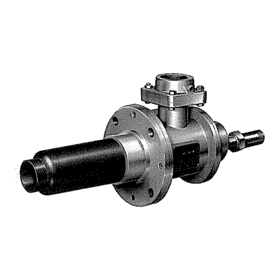
4. Installation Be very careful not to make an impact on the ceramic tube, or the burner may be damaged. Install the burner in such a way that it is free from any up/down, right/left excessive force. Do not cover the ceramic tube directly with any insulating material or the like as shown in the burner installation drawing. - Page 7 ・Burner installation drawing (CJ - 4) ・Dimension sheet Type A B φC φD φE φF □G □H φJ L CJ-4 For switching the existing burner to the CJ type burner, refer to the above installation drawing. - 5 -...
- Page 8 5. Piping 1. Direct good care to the inside of the pipe not to leave seal tape fractions, bond, cutting chips, etc. In connecting the pipes, provide pipe support in proper positions to prevent the application of any excess force. Provide a straight pipe part of about 6 times as large in diameter as the pipe before and behind the orifice flow meter 6.
- Page 9 7. Operation Preparing 1. Check to confirm that all the gas cocks have been closed. 2. Check for in-pipe gas leakage with air or nitrogen. 3. Check to confirm that each component unit of the air and gas lines are in normal operation. 4.
-
Page 10: Inspection (Burner Nozzle, Ceramic Tube)
Extinguishing 17. Fully close the cock and solenoid valve located immediately before the burner, and check to confirm that the fire has been extinguished. ※ Stop the combustion blower after the in-furnace temperature lowers to below 500 ℃ to protect the nozzle. 8. - Page 11 Hold the gas body firmly, and pull out the gas pipe , the burner nozzle , and the ④ ⑥ ⑤ ignition plug slowly and simultaneously. ⑦ Remove the union or the flange from the air piping. Loosen the hexagon headed bolts fixing the air body the furnace body.
-
Page 12: Warning Plate
Check the ceramic tube on the state of the inside and outside. If the combustion tube is broken, contact us for consultation as combustion may often be hampered. 11. Reassemble the burner by reversing the order of the above steps. ※... -
Page 13: Troubleshooting ・・・・11
10. Troubleshooting Do not ignite. Inspect the blower and each Gas supply and air component unit of the air line. supply are normal? Inspect each component unit the gas line. Check the ignition plug and the Does the ignition plug ignition transformer. -
Page 14: Structual Drawing
11. Structual Drawing (C J- 1, 2) Ultra Adapter (SU-10) Sight Hole (S-10) Plug R 1/8 Plug R 1/4 Hexagon Headed Bolt Hexagon Socket Head Cap Bolt Hexagon Socket Setscrew Hexagon Headed Bolt Flange Orifice Plate Packing Positioning Rod for Nozzle Ignition Plug Gas Pipe Burner Nozzle... - Page 15 (CJ - 3) Ultra Adapter (SU-10) Sight Hole (S-10) Plug R 1/8 Plug R 1/4 Hexagon Headed Bolt Hexagon Socket Head Cap Bolt Hexagon Socket Setscrew Hexagon Headed Bolt Flange Air Orifice Packing Ignition Plug Gas Pipe Burner Nozzle Gas Body Air Body Ceramic Tube Base Ceramic Tube...
- Page 16 (CJ - 4) Ceramic Press Down Packing Ceramic Receive Packing Ultra Adapter (SU-10) Sight Glass Plug R 1/8 Plug R 1/4 Lock Nut Hexagon Socket Head Cap Bolt Hexagon Headed Bolt Hexagon Socket Setscrew Flange Air Orifice Packing Ignition Plug Gas Pipe Gas Nozzle Air Nozzle...
Need help?
Do you have a question about the HOPE CJ and is the answer not in the manual?
Questions and answers