Table of Contents
Advertisement
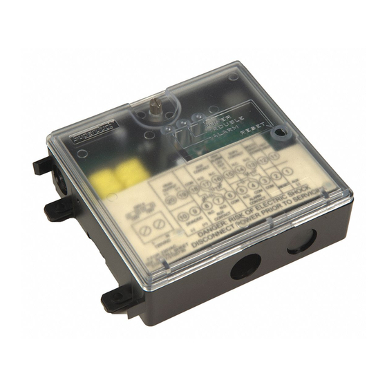
SuperDuct
Four-Wire Duct Smoke Detector
P/N 3100685 • Rev 1.0 • 05MAY04
Combination duct smoke sensor and controller
Duct smoke sensor
Content
Introduction ............................................................................1
Related documents ..................................................................2
Duct smoke detector limitations ...............................................2
Product description ...............................................................2
Overview ..................................................................................2
Features ...................................................................................4
Specifications ...........................................................................4
Accessories..............................................................................5
Operation ................................................................................5
Controls and indicators.............................................................5
Normal state.............................................................................6
Alarm state ...............................................................................6
Trouble state ............................................................................6
Multiple duct detector operation ...............................................7
Duct detector installation ......................................................7
Installation guidelines ...............................................................7
Wiring guidelines ......................................................................7
Installation sequence................................................................7
Changing sensor dirty test operation........................................7
Attaching a controller to a sensor in the field............................8
Technical Bulletin
SuperDuct Four-Wire Duct Smoke Detector
Sampling tubes ...................................................................... 8
Support for 36-inch or longer sampling tubes .......................... 8
Wiring...................................................................................... 9
Separating power-limited and nonpower-limited wiring ............ 9
Terminal identification .............................................................. 9
Wiring diagram ......................................................................... 9
Maintenance and service....................................................... 9
Recommended service schedule ............................................. 9
Sensor tests ............................................................................. 9
Controller tests ....................................................................... 10
Remote test/reset station tests............................................... 10
Troubleshooting ..................................................................... 11
Cleaning the duct smoke sensor ............................................ 11
Introduction
This document provides technical information for the
following SuperDuct™ duct smoke detector models:
Model number
TSD-CJ, ESD-CJ,
SD-CJ
TSD-SJ, ESD-SJ,
SD-SJ
Duct smoke sensor
controller
TSD-4WJ, ESD-4WJ,
SD-4WJ
TSD-CJG
TSD-SJG
TSD-CT, ESD-CT,
SD-CT,
TSD-ST, ESD-ST,
SD-ST
TSD-SJCO2
TSD-STCO2
Note:
evaluated to UL 2075.
Description
Four-wire duct smoke sensor
controller with RJ-45 modular
connectors
Four-wire duct smoke sensor with
RJ-45 modular connector
Combination four-wire duct smoke
sensor and controller with RJ-45
modular connectors
Four-wire duct smoke sensor
controller with RJ-45 modular
connectors and cover gasket
Four-wire duct smoke sensor with
RJ-45 modular connector and
cover gasket
Four-wire duct smoke sensor
controller with terminal block
connectors
Four-wire duct smoke sensor
assembly with terminal block
connector
Four-wire duct smoke sensor with
RJ-45 modular connector and
TSD-CO2 sensor module
Four-wire duct smoke sensor with
terminal block connector and TSD-
CO2 sensor module
The TSD-CO2 module has not been performance
1
Advertisement
Table of Contents


Need help?
Do you have a question about the SuperDuct TSD-CJ and is the answer not in the manual?
Questions and answers