
Related Manuals for Skye SKP 125 VS

Summary of Contents for Skye SKP 125 VS
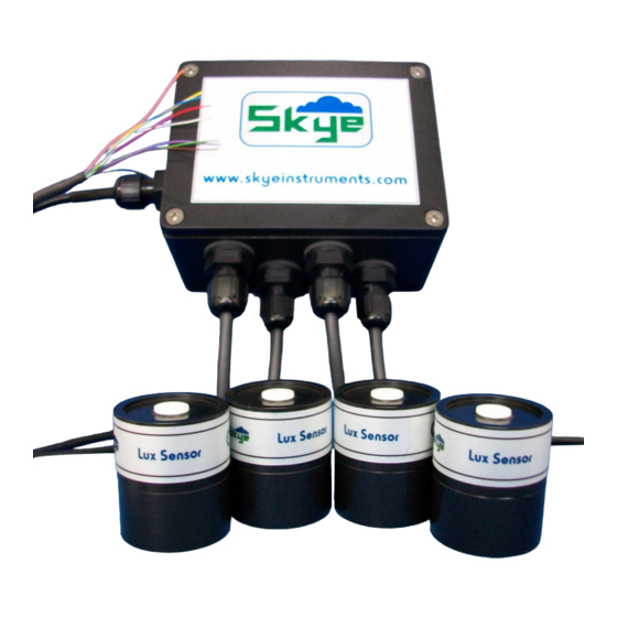
- Page 1 1 – 4 Channel External Amplifier SKP 125 VS Skye Instruments Ltd., 21 Ddole Enterprise Park, Llandrindod Wells, Powys LD1 6DF UK Tel: +44 (0) 1597 824811 skyemail@skyeinstruments.com www.skyeinstruments.com Iss. 1.1...
- Page 2 Skye Instruments Ltd. Skye Instruments is based in the UK and we are very proud to be celebrating being in business since 1983. Our products are designed and built in the UK. We have a very wide product base and our sensors &...
-
Page 3: Table Of Contents
CONTENTS Page INTRODUCTION TYPICAL APPLICATION Amplifier ......2 WIRING & POWER DETAILS Wiring ......3 Sensor Output & Power Supply......4 Connecting to Terminal ..5 HOUSING SPECIFICATIONS TROUBLESHOOTING... -
Page 4: Introduction
1 and 4 current output light sensors connected to it. This amplifier's function is to transform the current from one of Skye Instruments' unamplified sensors into a voltage output, scaled over a desired range pre- determined at the time of ordering (e.g. 0 – 2V, 0 – 5V, etc.). -
Page 5: Typical Application
1 – 4 Channel External Amplifier 2. TYPICAL APPLICATION 2.1 Amplifier The amplifier for each channel has had its level of amplification (gain) set at the time of manufacture and is not user changeable. Up to 4x Channel input Ch.1 Custom Voltage Output Ch.2 Ch.1 Amp. -
Page 6: Wiring & Power Details
Blue Serial #……………….. All Skye Instruments' current output light sensors are wired according to these colours. Please note that in terminal numbers 9 and 10, 4 wires are twisted together and placed within the one terminal opening. The sensor inputs are labelled with their unique serial numbers for identification. -
Page 7: Sensor Output & Power
1 – 4 Channel External Amplifier 3.2 Sensor Output & Power Supply The following table shows the typical outputs of Skye amplifiers, along with the power supply required for each. Sensor Output Power Supply Requirement 0 – 1V, 0 – 2V 5 - 15V 0 –... -
Page 8: Connecting To Terminal
1 – 4 Channel External Amplifier 3.3 Connecting to the Terminal Remove the lid slowly and gently as there is a wire attached to it that serves as the screening connection for the lid. Please also ensure that on replacing the lid that the wire does not get trapped in the sealing lip. Connecting wire ends to the terminal is intended to be easy. -
Page 9: Housing
1 – 4 Channel External Amplifier In diagram form: 4. HOUSING The housing is formed from an aluminium alloy, painted black. It is considered to be protected from ingress to IP65. On no account should it be subjected to immersion. The housing provides screening to the amplifiers and the screening of the lid is maintained by a connected wire. -
Page 10: Specifications
1 – 4 Channel External Amplifier 5. SPECIFICATIONS Cable: Black PVC 1m (max) between sensor and amplifier. 3m (longer available) wire ended for output connection. Cable connections: CLICK Cable Glands. Sealed to IP65 Humidity: 0 - 100% Temperature: C to +70 Power Requirements: 0 –... -
Page 11: Troubleshooting
1 – 4 Channel External Amplifier 6. TROUBLESHOOTING If you have any problems with using the external amplifier unit, please refer to this section. If you still have queries, do not hesitate to contact us via e-mail at: skyemail@skyeinstruments.com or by telephone on +44(0)1597 824 811. - Page 12 Skye Instruments Ltd., 21 Ddole Enterprise Park, Llandrindod Wells, Powys LD1 6DF UK Tel: +44 (0) 1597 824811 skyemail@skyeinstruments.com www.skyeinstruments.com...
Need help?
Do you have a question about the SKP 125 VS and is the answer not in the manual?
Questions and answers