
Related Manuals for GTM Professional GTS1300C


Summary of Contents for GTM Professional GTS1300C
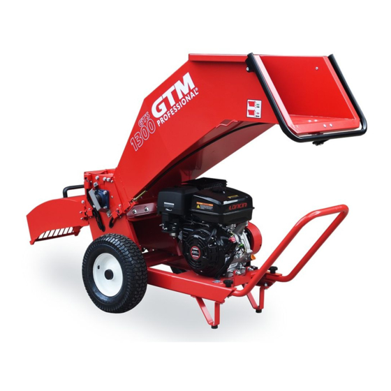
- Page 1 User manual GTS1300C Compo wood chipper low & high output English Original instructions D09-CC13S20-11...
- Page 2 Introduction Preface © Technische Handelmaatschappij J. De Wild B.V. This document or parts thereof may not be reproduced, copied, distributed, stored in a retrieval system, or transmitted in any form or by any means, electronically nor otherwise, without the prior written permission of Technische Handelmaatschappij J.
-
Page 3: Table Of Contents
Contents Contents Introduction....................6 About this document........................6 1.1.1 Purpose of this document....................6 1.1.2 Language.......................... 6 1.1.3 Illustrations........................6 1.1.4 Symbols used in this document..................6 About the machine and model types in this document..............7 How to use this document......................7 Contact information........................7 Warranty conditions........................ - Page 4 Contents Instructions for use..................23 Prepare for use........................... 23 Fill the fuel tank...........................23 Change the output........................24 Change to the high output..................... 24 Change to the low output.......................24 Start the machine........................24 Use the machine.........................25 Stop the machine........................25 Transport the machine........................25 Use the panic bar in case of an emergency................26 Release the panic bar.........................26 Preventive maintenance.................
- Page 5 Contents 7.3.1 Do a visual check......................39 7.3.2 Remove the output......................39 7.3.3 Remove the input......................41 7.3.4 Remove the blockage..................... 41 7.3.5 Use the rotor deblocking tool..................42 7.3.6 Finish..........................42 Replace a safety sign......................... 42 Troubleshooting..................43 General troubleshooting procedure.................... 43 Troubleshooting table.........................
-
Page 6: Introduction
Introduction Introduction About this document 1.1.1 Purpose of this document This document contains the information and instructions for an approved user to safely do these tasks: • Use the machine. • Do user maintenance on the machine. • Do user troubleshooting on the machine. For the requirements of the approved user, refer to section 1.1.2 Language... -
Page 7: About The Machine And Model Types In This Document
• For identification of the model type, refer to section • In this document, the wood chipper GTS1300C is referred to as the machine. How to use this document 1. Read this document completely. Make sure that you know and understand all the instructions. - Page 8 Introduction The warranty excludes: • Parts that are subject to wear. • Transport costs for part replacement. The warranty will be void when you do not obey these rules: • The machine must be operated by approved users. • Use the machine only as described in this document. •...
-
Page 9: Safety
Safety Safety Approved user A user must: • Be 18 years or older to operate the machine. • Never be under the influence of drugs or alcohol when operating the machine. • Be familiar with and obey the safety instructions. •... -
Page 10: Safety Signs On The Machine
Safety Safety signs on the machine D09-CC13S20-11... - Page 11 Safety Note: For an overview and explanation of the identification plate, refer to section Sign Description General warning Flying debris hazard Keep distance from the machine D09-CC13S20-11...
- Page 12 Safety Sign Description Cutting hazard Rotating parts hazard Noise level Read the manual Wear ear protection (mandatory PPE) Wear eye protection (mandatory PPE) Wear cut resistant gloves (mandatory PPE) V-belts running direction Hot surface hazard D09-CC13S20-11...
-
Page 13: Safety Instructions
Safety Sign Description Use of the panic bar, left-hand side Use of the panic bar, right-hand side Safety instructions 2.5.1 General safety instructions • Do not leave the working machine unattended. • Keep away from the discharge zone. • Do not wear loose clothing. •... -
Page 14: Safety Instructions For Maintenance, Transport And Storage
Safety • Make sure that the tire pressure of the machine is correct. Refer to section • Immediately stop the machine if the blades hit an unwanted object, if the machine makes an unusual sound or if the machine moves irregularly. 2.5.3 Safety instructions for maintenance, transport and storage •... -
Page 15: Description
Description Description Intended use The machine is a wood chipper designed to compose and to chip wood and roots. For an overview of the specifications of the material, refer to section Identification of the machine Technische Handelsmaatschappij J. de Wild B.V. De meeten 54 4706 NH Roosendaal THE NETHERLANDS... -
Page 16: Overviews
Description Overviews 3.3.1 Overview of the main components Pos. Item Description Deflector The deflector makes sure that the chipped material is put in the correct place. High output The output is used to guide the chipped ma- terial. Input The input is used to guide the entering mate- rial to the shredderbox. -
Page 17: Overview Of The Engine Controls
Description Pos. Item Description Shredderbox The shredderbox keeps the rotor in the cor- rect position. Safety lock switch The safety lock switch detects if the input and output are installed correctly. The ma- chine does not start if the parts are not instal- led correctly. -
Page 18: Installation
Installation Installation Note: Use bumper support to make sure that the machine stays balanced during installation. Install the input Warning: Two persons are required to install the input. The input is heavy. Preliminary requirements • Wrench size 13 Procedure 1. Lift the input (A). 2. -
Page 19: Install The Low Output
Installation Install the low output Caution: Never install the low and high output at the same time. 4.2.1 Remove the cover plate of the low output Preliminary requirements • Wrench size 13 Procedure 1. Remove the bolts (A). 2. Remove the cover plate (B). 4.2.2 Install the low output Preliminary requirements... -
Page 20: Install The High Output
Installation Procedure 1. Lift the output (A). 2. Position the output (A) in the openings of the shredderbox. 3. Tilt the output. 4. Make sure that the locking key (B) correctly fits in the safety lock switch (C). 5. Install the bolts (D). Install the high output Caution: Never install the low and high output at the same time. -
Page 21: Install The High Output
Installation 4.3.2 Install the high output Note: Make sure that the cover plate of the low output is installed. Preliminary requirements • Wrench size 13 Procedure 1. Lift the output (A). 2. Move the hinges (B) into the holes (C). 3. -
Page 22: Install The Handle
Installation Install the handle 1. Position the handle (A) on the frame (B). 2. Install the knobs (C). 3. Install the nuts (D). D09-CC13S20-11... -
Page 23: Instructions For Use
Instructions for use Instructions for use Prepare for use Warning: Do not use a damaged machine. 1. Remove all contamination from the work area. 2. Make sure that all machine parts are installed correctly. Refer to chapter Caution: You can only use the machine with either the low output or the high output. -
Page 24: Change The Output
Instructions for use Change the output Change to the high output 7.3.2 1. Remove the low output. Refer to section 2. Position the cover plate of the low output (A) on the shredderbox. 3. Make sure that te locking key (B) correctly fits in the safety lock switch 4. -
Page 25: Use The Machine
Instructions for use Procedure 1. Start the machine. Refer to the OEM documentation of the specific engine of your machine. Use the machine Note: • For an overview of the product specifications, refer to section • You can use the machine with either the low output or the high output. To change the output, refer to section 1. -
Page 26: Use The Panic Bar In Case Of An Emergency
Instructions for use 4. Put tie-down straps on the shredderbox (A) and through the hooks (B) of the input to secure the machine to the transporting vehicle. 5. Make sure that the machine cannot move during transport. Use the panic bar in case of an emergency Note: The panic bar can be activated at the bottom, left and right side of the input. -
Page 27: Preventive Maintenance
Preventive maintenance Preventive maintenance Warning: Before you do maintenance, make sure that: • The spark plug cap is disconnected. • The engine is cool. • The work area has sufficient light. Preventive maintenance schedule Task Frequency Procedure Do a functional test of the Before every use Refer to section panic bar... -
Page 28: Do A Detection Test Of The Input
Preventive maintenance Procedure 1. Remove the bolts (A) and the washers (B). 2. Start the machine and let it run idle. Refer to section 3. Do not put any material in the input. 4. Tilt the output (C) until the locking key is removed from the safety lock switch (D). -
Page 29: Clean The Machine
Preventive maintenance Procedure 1. Remove the bolts (A) and the washers (B). 2. Start the machine and let it run idle. Refer to 3. Do not put any material in the input. 4. Tilt the input (C) until the locking key is removed from the safety lock switch (D). -
Page 30: Replace The Air Filter
Preventive maintenance Procedure 1. Loosen the bolts (A). 2. Move the cover (B) in the direction of the arrow. 3. Hold the alignment ruler against the front of the pulleys to see if they are 6.11 aligned. Refer to section The tension is correct if you can push the belt down approximately 2 - 2,5 cm with a force of 50 N. -
Page 31: Fill The Engine With Oil
Preventive maintenance Fill the engine with oil Preliminary requirements • Spout • Engine oil Procedure 1. Stop the machine. Refer to section Warning: Make sure that the engine is still warm. Note: For the exact location of the drain plug (B), refer to the OEM documentation of the engine. -
Page 32: Replace The Belts
Preventive maintenance 6.10 Replace the belts Caution: Always replace the belts together. 6.10.1 Remove the cover Preliminary requirements • Wrench size 10 Procedure 1. Loosen the bolts (A). 2. Move the cover (B) in the direction of the arrow. 6.10.2 Remove the belts Preliminary requirements •... -
Page 33: Install The Belts
Preventive maintenance Procedure 1. Loosen the nuts (A) (6x) of the engine (B). 2. Move the engine in the direction of the arrow (C). 3. Remove and discard the belts (D). 6.10.3 Install the belts Preliminary requirements • Belt. Refer to the spare parts list for the exact type. Procedure 1. -
Page 34: Do A Check For Correct Operation
Preventive maintenance Procedure 1. Hold the alignment ruler against the front of the pulleys to see if they are 6.11 aligned. Refer to section 2. The tension is correct if you can push the belt (A) down approximately 2 - 2,5 cm (B) with a force of 50 N (C). - Page 35 Preventive maintenance 4. If there are gaps, use the nuts (C) to adjust the engine. 5. Repeat the steps 2, 3 and 4 until there are no gaps between the ruler and the pulley surfaces. 6. Put back the cover. D09-CC13S20-11...
-
Page 36: Corrective Maintenance
Corrective maintenance Corrective maintenance Note: Do the corrective maintenance procedures as required, or to solve a possible problem. Do maintenance on the blades Warning: • Speak to your dealer for these procedures. • Always wear cut resistant gloves when you do work on the blades. 7.1.1 Lock the rotor Preliminary requirements... -
Page 37: Turn The Blades
Corrective maintenance Procedure 1. Remove the bolts (5x) (A). 2. Remove the blade (B). 3. Remove the locking bolt (C). 4. Repeat the procedure for the second blade. 7.1.3 Turn the blades If one side of the blade is dull, you can turn the blade around to the sharper side. Preliminary requirements The blades are removed. -
Page 38: Install The Blades
Corrective maintenance Procedure 1. Sharpen the blade (A) to a maximum of 0.5 mm. 2. Make sure that you comply with the indicated angles. 3. Install the blade. Refer to section 7.1.5 7.1.5 Install the blades Preliminary requirements • Torque wrench •... -
Page 39: Finish
Corrective maintenance Procedure 1. Loosen the bolts (B) (5x). 2. Adjust the position of the counter blade (A). 3. Make sure that the gap (C) is between 0.5 and 1 mm. 4. Tighten the bolts (B). 5. Check the gap again. If necessary, repeat steps 1 to 4. - Page 40 Corrective maintenance Remove the low output Procedure 1. Remove the bolts (A). 2. Remove the output (B) from the shredderbox. Remove the high output Procedure 1. Remove the bolts (A) and the washers (B). 2. Tilt the output (C). 3. Remove the hinges (D) from the holes (E).
-
Page 41: Remove The Input
Corrective maintenance 7.3.3 Remove the input Note: Two persons are required to remove the input. The input is heavy. Preliminary requirements • Wrench size 13 Procedure 1. Remove the bolts (A) and the washers (B). 2. Tilt the input (C). 3. -
Page 42: Use The Rotor Deblocking Tool
Corrective maintenance 7.3.5 Use the rotor deblocking tool Preliminary requirements • Rotor deblocking tool • Wrench size 10 Procedure 1. Remove the bolts (A) and the washers (B). 2. Remove the bracket (C). 3. Remove the cover (D). 4. Move the rotor deblocking tool over the shaft of the rotor (E). -
Page 43: Troubleshooting
Troubleshooting Troubleshooting General troubleshooting procedure 1. Try to find a solution for the problem with the help of the troubleshooting table. 2. If you cannot find a solution for the problem, speak to your dealer. Refer to section Troubleshooting table Problem Possible cause Possible solution... -
Page 44: Technical Specifications
Technical specifications Technical specifications General specifications For an overview of the specifications of the engine of your machine, refer to the OEM documentation. Table 1: Compo wood chipper Item Specification Chipping method Drum chipper Blade types Double grinded blades (2x) Blade bolt tension [Nm] Counterblade Counterblade bolt tension [Nm]... -
Page 45: Material Specifications
Technical specifications Item Specification Transmission Double V-belts (2x) Dimensions - complete machine length [cm] width [cm] height [cm] Weight - complete machine [kg] 198.5 Sound power level [L Measured: 119 dB(A) Guaranteed: 120 dB(A) Compliant with Machinery Directive Accessories 1. Towbar 2. - Page 46 Technical specifications Item Specification length [mm] width [mm] height [mm] Capacity of fuel tank [l] Table 4: Mitsubishi GB40 Item Specification Power 9.56 kW/3600rpm Weight [kg] Dimensions length [mm] width [mm] height [mm] Capacity of fuel tank [l] Table 5: Loncin G420FD e-start Item Specification Power...
-
Page 47: Working Area
Technical specifications Working area Working area to control the machine, 1 meter wide. D09-CC13S20-11... -
Page 48: Danger Area
Technical specifications Danger area Danger area for the high output: area Danger area for the low output: area on which the chipped material falls on which the chipped material falls down. Radius is 12 meter. down. Radius is 12 meter. D09-CC13S20-11... -
Page 49: Wiring Diagram
Technical specifications Wiring diagram Spark plug Ignition coil SW1 panic bar detection input SW2 detection high output SW detection low output Engine on/off switch Earth / ground D09-CC13S20-11... - Page 50 Technical specifications D09-CC13S20-11...
- Page 51 Technical specifications D09-CC13S20-11...
Need help?
Do you have a question about the GTS1300C and is the answer not in the manual?
Questions and answers