Table of Contents
Advertisement
VL-E990E
1. SPECIFICATIONS .............................................................................................................................. 2
2. PART NAMES AND FUNCTION ......................................................................................................... 3
3. DISASSEMBLY OF THE SET ............................................................................................................. 4
4. MECHANISM ADJUSTMENT ........................................................................................................... 10
5. ADJUSTMENT OF VCR AND CAMERA ........................................................................................... 22
6. SYSTEM BLOCK DIAGRAMS .......................................................................................................... 35
7. SCHEMATIC DIAGRAMS ................................................................................................................. 42
8. SEMICONDUCTOR LEAD IDENTIFICATION .................................................................................. 80
9. PRINTED WIRING BOARD ASSEMBLIES ....................................................................................... 82
10.REPLACEMENT PARTS LIST .......................................................................................................... 93
11.PACKING OF THE SET .................................................................................................................. 111
SERVICE MANUAL
LIQUID CRYSTAL CAMCORDER Hi
MODELS
In the interests of user-safety (Required by safety regula-
tions in some countries) the set should be restored to its
original condition and only parts identical to those specified
be used.
CONTENTS
SHARP CORPORATION
1
S30Y3VL-A10S/
VL-A10S/H/E
VL-AH30S/H/E
Page
VL-A10S/H/E
VL-A10S/H/E
VL-AH30S/H/E
VL-AH30S/H/E
8
PAL
Advertisement
Table of Contents

Related Manuals for Sharp VL-A10S


Summary of Contents for Sharp VL-A10S
-
Page 1: Table Of Contents
VL-A10S/H/E VL-A10S/H/E VL-E990E VL-AH30S/H/E VL-AH30S/H/E SERVICE MANUAL S30Y3VL-A10S/ LIQUID CRYSTAL CAMCORDER Hi VL-A10S/H/E VL-AH30S/H/E MODELS In the interests of user-safety (Required by safety regula- tions in some countries) the set should be restored to its original condition and only parts identical to those specified be used. -
Page 2: Specifications
VL-A10S/H/E VL-E990E VL-AH30S/H/E 1. SPECIFICATIONS Signal System: PAL standard Recording System: 2 rotary heads, helical scanning system Cassette: 8 mm video tape, MP type or Hi8 MP, ME type Recording/Playback Time: 120 minutes (P5-120) Tape Speed: 20.051 mm/second Pickup Device: 1/4" (6.4mm, effective size: 4.5 mm) CCD image sensor (with approx. -
Page 3: Part Names And Function
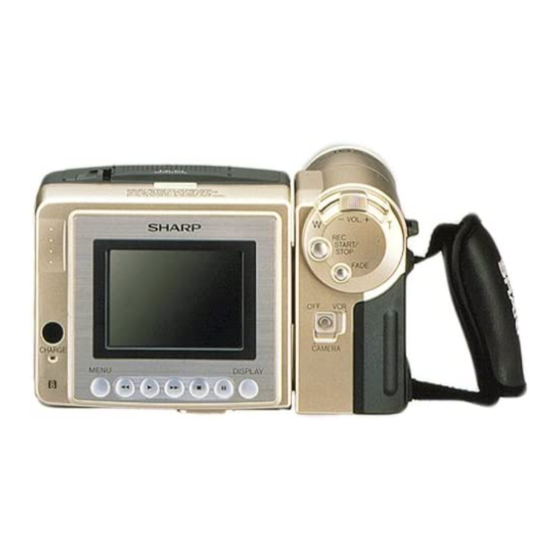
VL-A10S/H/E VL-E990E VL-AH30S/H/E 2. PART NAMES AND FUNCTION For details on the use of each control. -
Page 4: Disassembly Of The Set
VL-A10S/H/E VL-E990E VL-AH30S/H/E 3. DISASSEMBLY OF THE SET 3-1. REMOVAL OF THE CAMERA SECTION Note: Before removing the cabinet, turn off the power supply, and ascertain that the battery has been removed. Connector Pull out 5. Remove the connector of the 6-cell detection switch, and... - Page 5 VL-A10S/H/E VL-E990E VL-AH30S/H/E 3-2. DISASSEMBLY OF THE VCR MAIN BODY <1. Removal of the VCR lid shaft> Area A (2) Remove five screws ((b)LX-HZ0018TAFF). (1) Remove one screw ((k)LX-HZ0063TAFC). <Detail of area A> VCR lid Tilt frame C Frame V...
- Page 6 VL-A10S/H/E VL-E990E VL-AH30S/H/E <3. Removal of the VCR lid> Caution for installation of the VCR lid Microphone connector VCR lid Area B When installing the VCR lid, move the VCR lid in the arrow direction, keeping the VCR lid parallel to the main body as shown above.
- Page 7 VL-A10S/H/E VL-E990E VL-AH30S/H/E <8. Removal of the Lithium PWB> LCD unit Lithium PWB Main PWB Connector Connector Inverter transformer (1) Remove the connector of the Lithium PWB from the Main (3) Remove two screws ((b)LX-HZ0018TAFF) and two connec- PWB. tors, and remove the LCD unit (with inverter) from the main (2) Move the lithium unit in the direction of the arrow.
- Page 8 VL-A10S/H/E VL-E990E VL-AH30S/H/E Claw C Claw B View E Claw A Claw D View F Note: When fixing the cassette compartment lid, first engage the claws A and B, and then engage the claws C and D, verify that the four claws (A, B, C and D) of the cassette compartment lid are securely engaged as shown in the view above.
- Page 9 VL-A10S/H/E VL-E990E VL-AH30S/H/E 3-3. REPLACEMENT OF CCD SENSOR 3-3-1. BEFORE REPLACEMENT 1) The CCD image sensor is more sensitive to electrostatic breakage than C-MOS LSI. Therefore sufficient means to prevent electrostatic damage must be taken when it is replaced. • Ground the soldering iron.
-
Page 10: Mechanism Adjustment
VL-A10S/H/E VL-AH30S/H/E 4. MECHANISM ADJUSTMENT 4-1. MECHANISM CHECKING/ADJUSTING JIGS, TOOLS AND PARTS Configuration 1. Name 4-1-1. Mechanism checking/adjusting jigs and tools 2. Part No. 3. Code * Model, Uses Remarks <Note: The entries of list> 1. Torque gauge head 1. Cassette torquemeter 1. - Page 11 VL-A10S/H/E VL-AH30S/H/E 4-2. ITEMS AND TIMINGS OF INSPECTION AND MAINTENANCE The mechanism of VCR needs the following periodic inspection and maintenance in order that it maintains its high quality. Also, after the machine is repaired, execute the following maintenance and checks regardless of how long it has been used.
- Page 12 VL-A10S/H/E VL-AH30S/H/E 4-3. MECHANISM CHECKS AND ADJUSTMENTS The description given below relates to the general field services, but does not relate to the adjustment and replacement that require high level equipments, jigs, and technical skills. In order to maintain the initial characteristics of the machine, it is necessary to execute the maintenance and check and to prevent damage to tapes and other parts.
- Page 13 VL-A10S/H/E VL-AH30S/H/E 4-3-4. Checking and adjusting the tension pole position (1) Check – 0.5 When winding of P5-120 tape is started, check whether the tension pole is in the Si roller specified position against Si roller as shown or not.
- Page 14 VL-A10S/H/E VL-AH30S/H/E 4-4. ADJUSTMENT OF MECHANISM TAPE TRAVEL SYSTEM Sup tilted pole 4-4-1. Preparation for adjustment Tu GR Sup GR Tu tilted pole A (1) Clean the tape running areas (guide poles, rollers, drum, Tu tilted pole B Capstan shaft, Pinch roller) (Figure 1)
- Page 15 VL-A10S/H/E VL-AH30S/H/E 4-4-4. Adjusting the Tu guide Upper flange Height setting jig After replacement of Tu guide preset and adjust the height. Master plane (1) Tu guide height presetting (Figure 6) (JiGMP-MX7U) Adjust the height from the upper surface of mechanism chassis to the...
- Page 16 VL-A10S/H/E VL-AH30S/H/E 4-5. MECHANISM ASSEMBLING AND PARTS REPLACEMENT (DISASSEMBLING AND ASSEMBLING) Below is given an explanation of assembling of mechanism and its parts replacement. The removal of cabinet and Circuit Board is explained in the relevant service manual. Notes 1 After removal of cut washers be sure to replace them with new ones.
- Page 17 VL-A10S/H/E VL-AH30S/H/E 4-5-2. Cassette control ass’y Lock Lever Down Guide <Disassembling> (1) Set the unit to the EJECT mode, and let the housing stand upright. Or set the unit to the STANDBY mode, press the lock lever in the arrow direction, and let the housing stand upright.
- Page 18 VL-A10S/H/E VL-AH30S/H/E (4)-a Motor rotor ass'y and ro- Upper drum (4)-b Motor rotor ass'y (3) Upper drum ass’y ass'y tary transformer rotor (bonded type) (Both common type) (former type) ass'y Remove two screws fix- Remove the upper drum Remove the 2 rotor...
- Page 19 VL-A10S/H/E VL-AH30S/H/E (3) Lower drum ass'y Motor stator Tighten the FPC mounting screw to the lower drum ass'y. The screw Stator set tightening torque must be 0.08N·m (tighting torque 0.8kg·cm). (Fig- screw ure 6) (4) Upper drum ass’y After fitting the gap shim which was removed when the upper drum ass'y was dismantled to the shaft of lower drum ass’y, fit the upper...
- Page 20 VL-A10S/H/E VL-AH30S/H/E (4) Install the loading block assembly and the capstan motor. (7) Install the guide rail assembly taking care to position it (5) Install the drive gear. At this time, pay attention to the correctly. direction of gear. (The small gear must be located in the chassis side.)
- Page 21 VL-A10S/H/E VL-AH30S/H/E (8) Install the drum assembly in the chassis. (11) Install the slide chassis. (9) Install the tape guide in the drum assembly. (10) Install the Si roller. T arm guide Tape guide Slide this part towards the T arm.
-
Page 22: Adjustment Of Vcr And Camera
VL-A10S/H/E VL-AH30S/H/E 5. ADJUSTMENT OF VCR AND CAMERA 5-1. INITIAL SETTING OF E PROM IC 5-1-1. E PROM data alterable ways 1) Set the switch of main body to CAM, and use the remote control (RRMCG0033TASA) for adjustment to turn on the adjustment mode. - Page 23 VL-A10S/H/E VL-AH30S/H/E < Adjusting the video/LCD section > • Measuring instruments: *Color monitor TV set *Oscilloscope *DC cable (AC adapter accessory) *Digital voltmeter *Frequency counter *Video extension cables *DC power supply *Signal generator *Vector scope *Audio generator (CR oscillator) *AV output cable (accessory)
- Page 24 VL-A10S/H/E VL-AH30S/H/E • Types of test modes Contents TEST No. Title Sensor on/off Sensors off All sensors but the cassette controller switch, dew sensor and battery sensor stay off. Automatic battery sensor Battery sensor’s input voltage put in memory. adjustment Battery adjustment error Battery sensor’s adjustment errors are displayed at the right of...
- Page 25 VL-A10S/H/E VL-AH30S/H/E 5-3-2-3. Battery shut-off voltage adjusting method 1) Supply power to the main unit, using the variable-voltage DC power supply (range of 2.5V to 5.0V). 2) Set the CAM/OFF/VCR SW to CAM to switch to the camera mode. 3) Load a recordable tape and set the main unit to CAM REC. PAUSE.
- Page 26 VL-A10S/H/E VL-AH30S/H/E 5-3-3. Adjusting the VCR circuit 5-3-3-1. Adjusting the power • Test Points on the Video Circuit Board circuit a) POWER CIRCUIT ADJUSTMENT PROCEDURE Turn on power 1. Adjust to CAM 15V 2. Check P-CON 4.9V 3. Check P-CON 3.3V 4.
- Page 27 (Hi-8) MP 115±5mVP-P TL9413(Sig) Oscilloscope STOP REC Y current TL9414(Gnd) ME 165±5mVP-P adjustment (Nor 8) MP 135±5mVP-P · Nor8model (VL-A10S Series) Mode Address Measuring point Adjustment standard Measuring instrument REC Y current TL9413(Sig) MP 135±5mVP-P Oscilloscope adjustment (Nor 8)
- Page 28 VL-A10S/H/E VL-AH30S/H/E 5-3-6. Adjustment of audio circuit 1. Adjustment of filter f0 1) Set the alignment tape (JiGWR5-5CSP). 2) Using the adjustment remote controller (RRMCG0033TASA), Measuring instrument Oscilloscope set the VCR adjustment mode, and set the address “33” with Mode the operation switch (FF/REWIND key).
- Page 29 VL-A10S/H/E VL-AH30S/H/E 5. VCO adjustment Measuring point TL3802 Address Mode Adjusting method 1) Connect TL3803 to GND. 2) Connect the frequency counter to TL3802, and adjust the frequency. Adjustment standard 15.625kHz ± 100Hz Remarks ——————— 6. H-position adjustment Measuring point...
- Page 30 VL-A10S/H/E VL-AH30S/H/E 5-4. ADJUSTMENT OF CAMERA SECTION 5-4-1. Servicing of camera section (1) Object, measuring instrument and jigs necessary for camera section servicing • Gray scale chart • Color bar chart • Halogen light (2 pcs.) • Vectorscope • Color temperature conversion filter •...
- Page 31 VL-A10S/H/E VL-AH30S/H/E 5-4-2-1. Checking the power supply voltage • Measuring terminal: P-CON 4.9V P-CON 3.1V CAM 15V CAM -8V LENS 5.7V • Measuring instrument: Digital voltmeter 5-4-2-2. Auto focus adjustment • Basic iris adjustment Measuring instrument None DATA Adjustment Subject —...
- Page 32 VL-A10S/H/E VL-AH30S/H/E 4. White balance adjustment Measuring instrument Vector scope Spot Subject Gray scale Tape — VIDEO OUT (Terminated in 75 Ω) Test point Adjustment address R-W/B 00, B-W/B 02 R-W/B 17 % ± 3 % Adjustment level B-W/B -7 % ± 3 % 1) Adjust the spot to the center of vector scope (R-Y : 17%, B-Y : -7%) using address 00 and 02.
- Page 33 VL-A10S/H/E VL-AH30S/H/E 5-5. TROUBLE SHOOTING 5-5-1. Classification of troubles û Check the Power circuit and system control circuit. No function at all û No tape ejection Check the system control and loading motor circuit. û Check the inverter transformer and power circuit.
- Page 34 VL-A10S/H/E VL-AH30S/H/E 5-5-2. Troubleshooting for the camera section û Check the lens drive circuit (IC551) and main signal No picture line. û Check IC401 (DSP), and their peripherals. No color Check IC706 (camera CPU part of I chip µ-computer), û...
-
Page 35: System Block Diagrams
VL-A10S/H/E VL-AH30S/H/E 6. SYSTEM BLOCK DIAGRAMS NONREGE BATTERY IC900 IC701 3.0V POWER (SYS 3.0V) POWER (CAMERA) Power Control IC IC706 POWER (AT 3.0V) SYSTEM/SERVO CAMERA I CHIP µ-COM CONTROL CONTROL IC705 PROM PROM IC2701 LENS SERIAL BUS POWER (MOTOR) POWER (SIGNAL) - Page 36 VL-A10S/H/E VL-AH30S/H/E 6-1. VIDEO SIGNAL BLOCK DIAGRAM...
- Page 37 VL-A10S/H/E VL-AH30S/H/E 6-2. HEAD AMP BLOCK DIAGRAM...
- Page 38 VL-A10S/H/E VL-AH30S/H/E 6-3. POWER SYSTEM BLOCK DIAGRAM...
- Page 39 VL-A10S/H/E VL-AH30S/H/E 6-4. MAIN BATTERY CIRCUIT SECTION BLOCK DIAGRAM...
- Page 40 VL-A10S/H/E VL-AH30S/H/E 6-5. LENS DRIVE BLOCK DIAGRAM CCD SENSER ZOOM LENS MASTER LENS IC706 SYSCON IC101 DATA IC151 IC401 DATA IRIS, FOCUS, ZOOM CONTROL LENS DATA2 Master Lens POSI 20 19 (PHIRF) IRIS IC553 METER (HALL OFFSET) 4.9V OP-AMP IC102...
- Page 41 VL-A10S/H/E VL-AH30S/H/E - M E M O -...
-
Page 42: Schematic Diagrams
VL-A10S/H/E VL-AH30S/H/E 7. SCHEMATIC DIAGRAMS 7-1. OVERALL SCHEMATIC DIAGRAM 42~43... - Page 43 VL-A10S/H/E VL-AH30S/H/E 7-2. ADC SCHEMATIC DIAGRAM 44~45...
- Page 44 VL-A10S/H/E VL-AH30S/H/E 7-3. DSP SCHEMATIC DIAGRAM 46~47...
- Page 45 VL-A10S/H/E VL-AH30S/H/E 7-4. AUDIO SCHEMATIC DIAGRAM 48~49...
- Page 46 VL-A10S/H/E VL-AH30S/H/E 7-5. SYSCON SCHEMATIC DIAGRAM AH30 R4703 R4704 R731 R732 C705 C707 50~51...
- Page 47 VL-A10S/H/E VL-AH30S/H/E 7-6. LCD_INT SCHEMATIC DIAGRAM 52~53...
- Page 48 VL-A10S/H/E VL-AH30S/H/E 7-7. LCD_CTL SCHEMATIC DIAGRAM 54~55...
- Page 49 VL-A10S/H/E VL-AH30S/H/E 7-8. POWER SCHEMATIC DIAGRAM å AND SHADED COMPONENTS=SAFETY RELATED PARTS å 56~57...
- Page 50 VL-A10S/H/E VL-AH30S/H/E 7-9. I/O SCHEMATIC DIAGRAM 58~59...
- Page 51 VL-A10S/H/E VL-AH30S/H/E 7-10. SYSDAC SCHEMATIC DIAGRAM 60~61...
- Page 52 VL-A10S/H/E VL-AH30S/H/E 7-11. CHARGE SCHEMATIC DIAGRAM å AND SHADED COMPONENTS=SAFETY RELATED PARTS å å å 62~63...
- Page 53 VL-A10S/H/E VL-AH30S/H/E 7-13. RF SCHEMATIC DIAGRAM(VL-AH30) 66~67...
- Page 54 VL-A10S/H/E VL-AH30S/H/E 7-14. TG SCHEMATIC DIAGRAM 68~69...
- Page 55 VL-A10S/H/E VL-AH30S/H/E 7-15. CDS SCHEMATIC DIAGRAM 70~71...
- Page 56 VL-A10S/H/E VL-AH30S/H/E 7-16. LDRV SCHEMATIC DIAGRAM 72~73...
- Page 57 VL-A10S/H/E VL-AH30S/H/E 7-17. HEAD AMP SCHEMATIC DIAGRAM 74~75...
- Page 58 VL-A10S/H/E VL-AH30S/H/E 7-18. MOTOR DRIVER SCHEMATIC DIAGRAM 76~77...
- Page 59 VL-A10S/H/E VL-AH30S/H/E 7-19. CCD SCHEMATIC DIAGRAM 78~79...
-
Page 60: Semiconductor Lead Identification
VL-A10S/H/E VL-AH30S/H/E 8. SEMICONDUCTOR LEAD IDENTIFICATION RN1902 RN4984 XP4311 2SA1577R 2SA1362GR DTA144EE RN1903 RN4990 XP4316 2SA1989R CPH3209 2SA1774F RN1904 RN2902 XP4113 2SC5383F CPH3109 2SB12956 CPH6303 RN2903 HN1B01FU 2SC5384C RT1P241U 2SC4617B HN1B04FU RN2904 XP4501 RT1P141U RT1P441U 2SC4738Y HN1A01FU UMB2 UMZ1 RT1N441U... - Page 61 VL-A10S/H/E VL-AH30S/H/E EX0161TA MA729 EX0210TA MA2S111 EX0870CE F1J2H HVU362 HVU350B KV1812K HVU359TR FS1J2E F02J9 IX0616TA LB11952W IX0755TA IX0759TA IX0756TA BA7761KV IX0775TA BH7273KV ADS933Y LR38610 IX0474TA BH7272KV IX0422TA MB88344F IX0469TA CXA2096N NJM2904V UPC2391G BH7268KV MS548331 IX0468TA LB1990W IX0605TA MM1323XV IX0613TA MM1449XQ...
-
Page 62: Printed Wiring Board Assemblies
VL-A10S/H/E VL-AH30S/H/E 9. PRINTED WIRING BOARD ASSEMBLIES VCR PWB Component Side SIDE A R2935 C2911 C903 L903 C3602 R642 R2903 C211 Q905 R902 IC712 R2953 R3606 R3604 L904 Q2907 R2911 Q932 R2915 C3601 R2944 C750 D2909 C2906 R905 L909 C912... - Page 63 VL-A10S/H/E VL-AH30S/H/E VCR PWB Wiring Side SIDE A...
- Page 64 VL-A10S/H/E VL-AH30S/H/E VCR PWB Component Side SIDE B R2938 TL2920 C732 C2910 TL2909 R2937 R2946 TL2918 D2910 R757 C727 R2936 TL2906 Q2906 C2907 TL2922 R2939 R2949 C2908 TL2919 TL2910 P2901 R2925 TL2905 R2940 CP902 Q2914 TL2904 IC707 IC2902 Q2903 R2942...
- Page 65 VL-A10S/H/E VL-AH30S/H/E VCR PWB Wiring Side SIDE B...
- Page 66 VL-A10S/H/E VL-AH30S/H/E CAMERA PWB Component Side SIDE A TL556 TL557 TL559 TL560 TL565 TL566 TL567 TL568 TL570 P101 TL100 TL101 SC551 R130 TL552 TL554 TL558 TL118 TL551 TL553 TL555 TL11 Q551 TL12 TL562 TL564 TL13 TL14 TL561 TL563 TL15 R146...
- Page 67 VL-A10S/H/E VL-AH30S/H/E CAMERA PWB Wiring Side SIDE A...
- Page 68 VL-A10S/H/E VL-AH30S/H/E CAMERA PWB Component Side SIDE B R582 P102 R580 R570 C566 R569 R562 R571 C572 TL136 R148TL135 IC553 R568 C569 R107 R567 R108 C573 R566 R103 R565 C567 R105 R104 C105 TL102 TL149 R121 C103 IC101 TL148 R120...
- Page 69 VL-A10S/H/E VL-AH30S/H/E CAMERA PWB Wiring Side SIDE B...
- Page 70 VL-A10S/H/E VL-AH30S/H/E HEAD AMP PWB Component Side SIDE A R3731 R3718 R3717 R3730 TL3752 C3709 TL3705 R3715 R3716 TL3721 TL3722 C3710 C3712 C3713 C3716 C3715 C3717 C3718 TL3708 R3721 IC3701 TL3704 C3720 R3703 R3722 TL3732 TL3703 TL3707 C3723 C3725 C3727...
- Page 71 VL-A10S/H/E VL-AH30S/H/E HEAD AMP PWB Wiring Side SIDE A...
- Page 72 VL-A10S/H/E VL-AH30S/H/E HEAD AMP PWB Wiring Side SIDE B...
-
Page 73: Replacement Parts List
RN2904 PRINTED WIRING BOARD ASSEMBLIES Q709 VSHN1C01FU/-1 HN1C01FU (NOT REPLACEMENT ITEM) Q901 VS2SA2010//-1 2SA2010 Q903 VS2SA1989R/-1 2SA1989R Q904 VS2SA1362GR-1 2SA1362GR DUNTK2950QA10 VCR Unit(VL-A10S) — Q905 VS2SA1989R/-1 2SA1989R DUNTK2950QA11 VCR Unit — Q906 VS2SA2010//-1 2SA2010 (VL-A10E/EW/EX) Q908 VS2SA1362GR-1 2SA1362GR DUNTK2950QA12 VCR Unit(VL-AH30S) —... - Page 74 VL-A10S/H/E VL-E990E VL-AH30S/H/E Ref. No. Part No. Description Code Ref. No. Part No. Description Code Q2903 VSFTS1001//-1 FTS1001 X701 RCRSC0170TAZZ Crystal, CRSC0170TA Q2905 VS2SB1205S/-1 2SB1205S X702 RCRSC0032TAZZ Crystal, CRSC0032TA Q2906 VSRN1902///-1 RN1902 Q2907 VSRN1902///-1 RN1902 COILS AND TRANSFORMER Q2910 VSRN4983///-1...
- Page 75 VL-A10S/H/E VL-E990E VL-AH30S/H/E Ref. No. Part No. Description Code Ref. No. Part No. Description Code C607 VCKYCZ1CB103K 0.01 16V Ceramic L8404 VPD9M221J210N Peaking, 220µH C608 VCKYCZ1CB103K 0.01 16V Ceramic L8405 VP-1M391J330N Peaking, 390µH C609 VCKYCY1CF334Z 0.33 16V Ceramic L8451 VPD9M820J9R5N Peaking, 82µH...
- Page 76 VL-A10S/H/E VL-E990E VL-AH30S/H/E Ref. No. Part No. Description Code Ref. No. Part No. Description Code C1908 VCKYCZ1AB104K 10V Ceramic C902 RC-KZ0070TAZZ 16V Ceramic C1909 VCKYCZ1AB104K 10V Ceramic C903 RC-KZ0070TAZZ 16V Ceramic C1910 VCKYCZ1AB104K 10V Ceramic C904 RC-KZ0070TAZZ 16V Ceramic C1911...
- Page 77 VL-A10S/H/E VL-E990E VL-AH30S/H/E Ref. No. Part No. Description Code Ref. No. Part No. Description Code C7409 VCKYCZ1CB103K 0.01 16V Ceramic R451 VRS-CZ1JF392J 3.9k 1/16W Metal Oxide AA C7410 VCCCCY1HH221J 220p 50V Ceramic R452 VRS-CZ1JF823D 82k 1/16W Metal Oxide AB C7411...
- Page 78 VL-A10S/H/E VL-E990E VL-AH30S/H/E Ref. No. Part No. Description Code Ref. No. Part No. Description Code R738 VRS-CZ1JF104J 100k 1/16W Metal Oxide AA R925 VRS-CZ1JF753J 75k 1/16W Metal Oxide AA R740 VRS-CZ1JF473J 47k 1/16W Metal Oxide AA R926 VRS-CZ1JF393J 39k 1/16W Metal Oxide AA...
- Page 79 VL-A10S/H/E VL-E990E VL-AH30S/H/E Ref. No. Part No. Description Code Ref. No. Part No. Description Code R1916 VRS-CZ1JF153J 15k 1/16W Metal Oxide AA R2419 VRS-CZ1JF102J 1/16W Metal Oxide AA R1917 VRS-CZ1JF103J 10k 1/16W Metal Oxide AA R2420 VRS-CZ1JF222J 2.2k 1/16W Metal Oxide AA...
- Page 80 VL-A10S/H/E VL-E990E VL-AH30S/H/E Ref. No. Part No. Description Code Ref. No. Part No. Description Code R3842 VRS-CZ1JF153J 15k 1/16W Metal Oxide AA R7459 VRS-CZ1JF391J 390 1/16W Metal Oxide AA R3843 VRS-CZ1JF104J 100k 1/16W Metal Oxide AA R7460 VRS-CZ1JF271J 270 1/16W Metal Oxide AA...
- Page 81 VL-A10S/H/E VL-E990E VL-AH30S/H/E Ref. No. Part No. Description Code Ref. No. Part No. Description Code DUNTK2935QA10(VL-A10S/H/AH30S/H) C113 VCSATA1AJ106M 10V Tantalum DUNTK2935QA11(VL-A10E/EW/EX/AH30E/EX) C114 VCKYCZ1AF104Z 10V Ceramic C115 VCSATA1AJ106M 10V Tantalum CAMERA UNIT C116 VCKYCZ1AF104Z 10V Ceramic C117 VCCCCZ1HH150J 50V Ceramic INTEGRATED CIRCUITS...
- Page 82 VL-A10S/H/E VL-E990E VL-AH30S/H/E Ref. No. Part No. Description Code Ref. No. Part No. Description Code C304 VCKYCZ1CB103K 0.01 16V Ceramic R565 VRS-CZ1JF912J 9.1k 1/16W Metal Oxide AB C305 VCSATA1AJ156M 10V Tantalum R566 VRS-CZ1JF104J 100k 1/16W Metal Oxide AA C306 VCSATA1AJ156M...
- Page 83 VL-A10S/H/E VL-E990E VL-AH30S/H/E Ref. No. Part No. Description Code Ref. No. Part No. Description Code VRS-CY1JF472J 4.7k 1/16W Metal Oxide AA R335 VRS-CY1JF273J 27k 1/16W Metal Oxide AA VRS-CY1JF101J 100 1/16W Metal Oxide AA R337 VRS-CZ1JF181J 180 1/16W Metal Oxide AA...
- Page 84 VL-A10S/H/E VL-E990E VL-AH30S/H/E Ref. No. Part No. Description Code Ref. No. Part No. Description Code MECHANISM PARTS TLABH0584GEZZ Caution Label PSHEM0014GEZZ Counter Balance PSHEP0013GEZZ Interruption Sheet LCHSM0163GEZZ Main Chassis Ass'y XAPSF17P03200 Screw M1.7x3.2 NGERH1280GEZZ Main Cam LX-XZ3036GEFP Screw M2.0x6.0 NGERH1281GEZZ...
- Page 85 VL-A10S/H/E VL-E990E VL-AH30S/H/E Ref. No. Part No. Description Code Ref. No. Part No. Description Code RUNTK0354TAZZ Lithium Battery Unit LHLDZ1532TAZZ Battery Lock Holder GCOVA1651TAKA Microphone Cover 6-10 MLEVP0044TASA Battery Lock Lever QPWBH2815TAZZ CCD FPC 6-11 MSPRC0101TAFJ Battery Push-out Spring CCOVA1652LMV2...
- Page 86 VL-A10S/H/E VL-E990E VL-AH30S/H/E Ref. No. Part No. Description Code Ref. No. Part No. Description Code SUPPLIED ACCESSORIES CASSETTE HOUSING PARTS CHLDX3077GE01 Cassette Compartment ACCESSORIES Ass'y GCOVH1225TASA Lens Cap MSPRT0414GEZZ Up Main Spring å QACCB0016TAZZ AC Cable MROD-0014GEFJ Damper rod (A10H/EW/AH30H) å...
- Page 87 VL-A10S/H/E VL-E990E VL-AH30S/H/E Ref. No. Part No. Description Code Ref. No. Part No. Description Code PACKING PARTS (NOT REPLACEMENT ITEM) SPAKC7521TAZZ Packing Case(A10S) — SPAKC7522TAZZ Packing Case(A10H) — SPAKC7523TAZZ Packing Case(A10E/EX) — SPAKC7524TAZZ Packing Case(A10EW) — SPAKC7525TAZZ Packing Case(AH30S) —...
- Page 88 VL-A10S/H/E VL-E990E VL-AH30S/H/E MECHANISM CHASSIS EXPLODED VIEW Ref. No. Part No. Description Code Ref. No. Part No. Description Code...
- Page 89 VL-A10S/H/E VL-E990E VL-AH30S/H/E Ref. No. Part No. Description Code Ref. No. Part No. Description Code CABINET EXPLODED VIEW 6-14 6-12 6-11 6-10 56-2 6-13...
- Page 90 VL-A10S/H/E VL-E990E VL-AH30S/H/E CASSETTE HOUSING CONTROL UNIT EXPLODED VIEW Ref. No. Part No. Description Code Ref. No. Part No. Description Code CAMERA UNIT EXPLODED VIEW The mark must be on the face. Lens side side Mark Face the thinner part...
-
Page 91: Packing Of The Set
VL-A10S/H/E VL-E990E VL-AH30S/H/E 11. PACKING OF THE SET Ref. No. Part No. Description Code Ref. No. Part No. Description Code No.12 No.22 No.2 No.10 No.5, No.6, No.7, No.8, No.9 No.4 No.16 No.19 No.11 No.24 No.20 No.21 No.3 No.13 No.15 No.14 No.17... - Page 92 Code Ref. No. Part No. Description Code COPYRIGHT C 2000 BY SHARP CORPORATION ALL RIGHTS RESERVED. No part of this publication may be reproduced, stored in a retrieval system, or transmitted in any form or by any means, electronic, mechanical, photocopying, recording, or otherwise, without prior written permission of the publisher.
Need help?
Do you have a question about the VL-A10S and is the answer not in the manual?
Questions and answers