Table of Contents
Advertisement
Quick Links
Covers Models:
1184/1186, 1185, 1194/1196
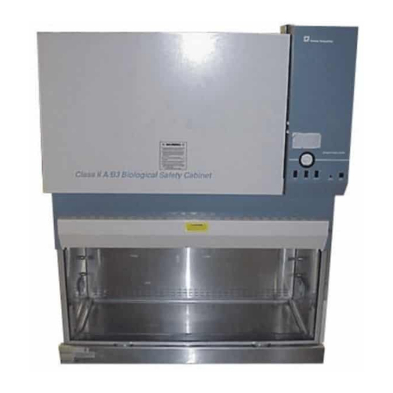
Biological Safety Cabinet
Class Ii, Type A/B3
Manual 7001186
IMPORTANT: READ THIS TECHNICAL MANUAL CAREFULLY TO DETERMINE
PROPER INSTALLATION, OPERATION, AND USAGE PROCEDURES. PAY CAREFUL
ATTENTION TO ALL CAUTIONS AND WARNINGS.
CAUTION: ALL INTERNAL ADJUSTMENTS AND MAINTENANCE MUST BE
PERFORMED BY QUALIFIED SERVICE PERSONNEL.
March 1992
Advertisement
Chapters
Table of Contents

Subscribe to Our Youtube Channel
Related Manuals for Forma Scientific 1184


Summary of Contents for Forma Scientific 1184
- Page 1 Covers Models: 1184/1186, 1185, 1194/1196 Biological Safety Cabinet Class Ii, Type A/B3 Manual 7001186 IMPORTANT: READ THIS TECHNICAL MANUAL CAREFULLY TO DETERMINE PROPER INSTALLATION, OPERATION, AND USAGE PROCEDURES. PAY CAREFUL ATTENTION TO ALL CAUTIONS AND WARNINGS. CAUTION: ALL INTERNAL ADJUSTMENTS AND MAINTENANCE MUST BE PERFORMED BY QUALIFIED SERVICE PERSONNEL.
- Page 2 INDEX PAGE SECTION 1 – RECEIVING Preliminary Inspection Visible Loss or Damage Concealed Loss or Damage Responsibility for Shipping Damage Unpacking List SECTION 2 - INTRODUCTION Description Theory of Operation Airflow Diagram (Fig. 2.0) SECTION 3 - INSTALLATION OF CABINET Location Power Connection Plumbing Connection...
- Page 3 L) Exhaust Filter Guard M) Hinged Window Assembly N) Sliding Window Assembly Overview of Cabinet Dwg 4.0 Overview of Control Panel Dwg. 4.1 (Model 1184/1186) 18 Overview of Control Panel Dwg. 4.2 (Model 1194/1196) 19 SECTION 5 - GENERAL CAUTIONS General Caution Notes...
- Page 4 BSC Test Grids (Model 1184/1186) BSC Test Grids (Model 1186/1196) SECTION 9 - SPECIFICATIONS Model 1184 (4' Cabinet with sliding window) Model 1185 (4’ Cabinet with sliding window) Model 1186 (6' Cabinet with sliding window) Model 1194 (4' Cabinet with hinged window)
- Page 5 SECTION 1 - RECEIVING Table of Contents 1.1 Preliminary Inspection 1.2 Visible Loss or Damage 1.3 Concealed Loss or Damage 1.4 Responsibility for Shipping Damage 1.5 Unpacking List...
- Page 6 On F.O.B. Destination shipments, Forma Scientific's and the carrier's responsibility ends when your Receiving Department personnel sign a free and clear delivery receipt. Whenever possible, Forma Scientific, Inc. will assist in settling claims for loss or in-transit damage. 1.5 UNPACKING LIST The "Installation/Operation"...
- Page 7 SECTION 2 - INTRODUCTION Table of Contents 2.1 Description 2.2 Theory of Operation 2.3 Airflow Diagram (Fig. 2.0)
- Page 8 2.1 DESCRIPTION The Model 1184/1186/1194/1196 Series is a Class II, Type A/B3 cabinet. The "Type A/B3" designation indicates two alternative uses of the cabinet. When vented directly into the laboratory room, the unit serves a "Type A" unit. When vented to the outside atmosphere, through an in-house exhaust system, it serves as a "Type B3"...
- Page 9 2.3 AIRFLOW DIAGRAM FIGURE 2.0...
- Page 10 SECTION 3 - INSTALLATION OF CABINET Table of Contents 3.1 Location 3.2 Power Connection 3.3 Plumbing Connection 3.4 Exhaust Requirements...
- Page 11 NOTE: Identification INDEX BUTTONS are supplied. The cabinet will support a TOTAL of six service valves. The additional four service valves may be purchased from Forma Scientific Inc. CAUTION! EXPLOSIVE/FLAMMABLE SUBSTANCES SHOULD NEVER BE USED IN THE CABINET, UNLESS APPROVED AND MONITORED BY A BIOLOGICAL SAFETY...
- Page 12 The intermediate connection of the cabinet to any external exhaust system (in-house) can be performed by using an exhaust transition, which is available for purchase from Forma Scientific Inc. This exhaust transition requires a minimum of 16-1/2" headroom from the top of the cabinet.
-
Page 13: Table Of Contents
Blower Motor/Lights Reset Button (15 Amp) Receptacle Reset Button (15 Amp) Duplex Receptacles Drain Valve Service Valves M) Exhaust Filter Guard Sliding Window Assembly 4.2 Overview of Cabinet Drawing 4.3 Overview of Control Panel (Models 1184/1186) 4.4 Overview of Control Panel (Models 1194/1196) -
Page 14: 4.1 Control & Indicating Devices
4.1 CONTROL & INDICATING DEVICES (REFER TO DRAWINGS 4.0, 4.1 and 4.2 FOR PROPER IDENTIFICATION) Before operating the cabinet, it is recommended that the user(s) become familiar with the following items on the cabinet. A) BLOWER SWITCH The blower switch controls the on/off power to the internal blower. B) LIGHT SWITCH The "dual purpose"... - Page 15 E) STATIC PRESSURE GAUGE (IN. W.G.) The static pressure gauge, located on the control panel, measures the air pressure differential across the filters, providing an indication of filter "loading". As the filters become loaded, the resistance to air passage increases, and the reading on the static pressure gauge increases accordingly. When the reading increases by 50% (from original measurement), cabinet airflow should be checked with a thermoanemometer, by a qualified service technician.
- Page 16 NOTE: Identification INDEX BUTTONS are supplied. The cabinet will support a TOTAL of six service valves. Additional service valves may be purchased from Forma Scientific Inc.
-
Page 17: N) Sliding Window Assembly
L) EXHAUST FILTER GUARD The exhaust filter guard, located on top of the exhaust filter, prevents the storage of objects on the housing and protects exhaust air flow. M) HINGED WINDOW ASSEMBLY The hinged window assembly allows the operator to raise the glass window to place product/auxilliary equipment, etc. - Page 18 SECTION 4.2 DRAWING #4.0 OVERVIEW OF CABINET...
-
Page 19: Overview Of Control Panel (Models 1184/1186)
SECTION 4.3 DRAWING #4.1 OVERVIEW OF 1184/1186 CONTROL PANEL... -
Page 20: Overview Of Control Panel (Models 1194/1196)
SECTION 4.4 DRAWING #4.2 OVERVIEW OF 1194/1196 CONTROL PANEL... - Page 21 SECTION 5 - GENERAL CAUTIONS Table of Contents 5.1 General Caution Notes 5.2 Important Label Location Drawing...
- Page 22 5.1 GENERAL CAUTION NOTES CAUTION NOTES 1. FOLLOWING INITIAL INSTALLATION, THE UNIT MUST BE THOROUGHLY TESTED AND CERTIFIED. 2. ALL ACTIVITIES TO BE PERFORMED WITHIN THE CABINET SHOULD BE APPROVED BY A BIOLOGICAL SAFETY OFFICER OR OTHER QUALIFIED INDIVIDUAL. 3. SINCE THE HEPA FILTERS REMOVE PARTICULATES ONLY (NOT GAS), EXPLOSIVE/FLAMMABLE SUBSTANCES SHOULD NEVER BE USED IN THE CABINET, UNLESS APPROVED AND MONITORED BY A BIOLOGICAL SAFETY OFFICER OR OTHER QUALIFIED INDIVIDUAL.
- Page 23 5.2 IMPORTANT LABEL LOCATION DRAWING...
- Page 24 SECTION 6 - CABINET START-UP Table of Contents 6.1 General Recommendations 6.2 Use of Auxiliary Equipment in the Cabinet 6.3 Cabinet Check 6.4 Start-Up Procedure...
- Page 25 6.1 GENERAL RECOMMENDATIONS 1) Keep the movement in the room to a minimum when the cabinet is in use. 2) Keep all laboratory doors closed to prevent drafts that will disturb critical air flow characteristics. 3) Pre-plan cabinet use, and place everything required for the complete procedure in the cabinet so that nothing passes through the air barrier (in or out) during the procedure.
- Page 26 6.3 CABINET CHECK 1) Check to see that the DRAIN VALVE is closed (handle in a horizontal position), so that if a spill should occur on the work surface, it will remain in the drain system and not drain onto the laboratory floor and cause contamination.
- Page 27 SECTION 7 - TROUBLESHOOTING Table of Contents 7.1 Troubleshooting Guide...
- Page 28 7.1 TROUBLESHOOTING GUIDE The following is intended as a guide to troubleshooting the system should a problem develop. If a "contaminated" area of the cabinet must be entered to determine and/or resolve the source of a particular problem, THE CABINET MUST FIRST BE DECONTAMINATED. CAUTION: ACTUAL SERVICING OF THE UNIT MUST BE PERFORMED BY QUALIFIED SERVICE PERSONNEL ONLY! PROBLEM 1: AIR FLOW IN THE CABINET WORK AREA AND THROUGH THE EXHAUST...
- Page 29 PROBLEM 3: FLUORESCENT LIGHT MALFUNCTION POSSIBLE CAUSES: 1) Check lamp pins and socket ends for contact. 2) Defective lamp. PROBLEM 4: LOUD SCREECHING NOISE POSSIBLE CAUSES: 1) Indicates bad bearings in motor blower unit. 2) Blower scroll is rubbing against housing.
- Page 30 SECTION 8 - ROUTINE MAINTENANCE Table of Contents 8.1 Checking the Static Pressure Gauge "Zero" 8.2 Re-zeroing the Static Pressure Gauge 8.3 Adjusting the Damper 8.4 Biological Safety Cabinet Test Grids...
- Page 31 8.1 CHECKING THE STATIC PRESSURE GAUGE "ZERO" NOTE: In order to provide an accurate reading, the indicating needle of the static pressure gauge should be precisely at zero when the cabinet is completely shut off. If the cabinet is connected to a central exhaust system, the exhaust system must also be shut off.
- Page 32 8.3 ADJUSTING THE DAMPER Since the HEPA filter resistance may vary considerably from filter to filter (even filters of the same size), a damper has been installed in the cabinet exhaust system for maintaining proper airflow balance. The purpose of the damper is to regulate the amount of exhaust air, intake velocity and supply velocity.
- Page 33 8.4 BIOLOGICAL SAFETY CABINET TEST GRIDS (MODELS 1184/1185/1194)
- Page 34 8.5 BIOLOGICAL SAFETY CABINET TEST GRIDS (MODELS 1186/1196)
- Page 35 SECTION 9 - SPECIFICATIONS Table of Contents 9.1 Model 1184 (4' Cabinet with sliding window) 9.2 Model 1185 (4' Cabinet with sliding window) 9.2 Model 1186 (6' Cabinet with sliding window) 9.3 Model 1194 (4' Cabinet with hinged window) 9.4 Model 1196 (6' Cabinet with hinged window)
-
Page 36: Model 1184 (4' Cabinet With Sliding Window)
9.1 MODEL - 1184 (4' CABINET WITH SLIDING WINDOW) ~ CONSTRUCTION Work Surface: Type 304 Stainless Steel, #4 Finish Cabinet: Cold Rolled Steel Finish: Antique White with Windsor Blue Trim Baked-on Powder Coat Epoxy Paint ~ DIMENSIONS Exterior: 54"W x 64"H x 32.5"F-B Interior: 49"W x 28.33"H x 22.25"F-B... -
Page 37: Model 1185 (4' Cabinet With Sliding Window)
9.2 MODEL - 1185 (4' CABINET WITH SLIDING WINDOW) ~ CONSTRUCTION Work Surface: Type 304 Stainless Steel, #4 Finish Cabinet: Cold Rolled Steel Finish: Antique White with Windsor Blue Trim Baked-on Powder Coat Epoxy Paint ~ DIMENSIONS Exterior: 54"W x 64"H x 32.5"F-B Interior: 49"W x 28.33"H x 22.25"F-B ~ ELECTRICAL REQUIREMENTS Main: 220 VAC, 1 Phase, 2 Wire, 50 Hz, 6 FLA... -
Page 38: Model 1186 (6' Cabinet With Sliding Window)
9.3 MODEL - 1186 (6' CABINET WITH SLIDING WINDOW) ~ CONSTRUCTION Work Surface: Type 304 Stainless Steel, #4 Finish Cabinet: Cold Rolled Steel Finish: Antique White with Windsor Blue Trim Baked-on Powder Coat Epoxy Paint ~ DIMENSIONS Exterior: 78"W x 64"H x 32.5"F-B Interior: 73"W x 28.33"H x 22.25"F-B ~ ELECTRICAL REQUIREMENTS Main: 100-125 VAC, 1 Phase, 2 Wire, 60 Hz, 12 FLA... -
Page 39: Model 1194 (4' Cabinet With Hinged Window)
9.4 MODEL - 1194 (4' CABINET WITH HINGED WINDOW) ~ CONSTRUCTION Work Surface: Type 304 Stainless Steel, #4 Finish Cabinet: Cold Rolled Steel Finish: Antique White with Windsor Blue Trim Baked-on Powder Coat Epoxy Paint ~ DIMENSIONS Exterior: 54"W x 64"H x 32.5"F-B Interior: 49"W x 28.33"H x 22.25"F-B ~ ELECTRICAL REQUIREMENTS Main: 100-125 VAC, 1 Phase, 2 Wire, 60 Hz, 10 FLA... -
Page 40: Model 1196 (6' Cabinet With Hinged Window)
9.5 MODEL - 1196 (6' CABINET WITH HINGED WINDOW) ~ CONSTRUCTION Work Surface: Type 304 Stainless Steel, #4 Finish Cabinet: Cold Rolled Steel Finish: Antique White with Windsor Blue Trim Baked-on Powder Coat Epoxy Paint ~ DIMENSIONS Exterior: 78"W x 64"H x 32.5"F-B Interior: 73"W x 28.33"H x 22.25"F-B ~ ELECTRICAL REQUIREMENTS Main: 100-125 VAC, 1 Phase, 2 Wire, 60 Hz, 12 FLA... - Page 41 SECTION 10 - ACCESSORIES 10.1 Accessories (Chart)
- Page 43 SECTION 11 - REPLACEMENT PARTS 11.1 Model 1184/1185 Replacement Parts 11.2 Model 1186 Replacement Parts 11.3 Model 1194 Replacement Parts 11.4 Model 1196 Replacement Parts...
- Page 44 11.1 MODEL 1184/1185 - REPLACEMENT PARTS STOCK # DESCRIPTION 191510 1184, 4' Sliding Window 156079 3/4 HP Blower Motor (1625 RPM) 170045 Capacitor, Motor 25MFD, 370V 190109 Triac Speed Control, Type C 225250 Ballast (Fluorescent Lighting) 225414 48" Fluorescent Lamp (60W, 120V)
- Page 45 11.2 MODEL 1186 - REPLACEMENT PARTS STOCK # DESCRIPTION 191511 1186, 6' Sliding Window 156039 3/4 HP Blower Motor (1050 RPM) 170039 Capacitor, Motor 15MFD, 370V 190109 Triac Speed Control, Type C 225250 Ballast (Fluorescent Lighting) 225418 72" Fluorescent Lamp (85W, 120V) 230054 Circuit Breaker, 15A SP 430200...
- Page 46 11.3 MODEL 1194 - REPLACEMENT PARTS STOCK # DESCRIPTION 191530 1194, 4' Hinged Window 156079 3/4 HP Blower Motor (1625 RPM) 170045 Capacitor, Motor 25MFD, 370V 190109 Triac Speed Control, Type C 225250 Ballast (Fluorescent Lighting) 225414 48" Fluorescent Lamp (60W, 120V) 230054 Circuit Breaker, 15A SP 430200...
- Page 47 11.4 MODEL 1196 - REPLACEMENT PARTS STOCK # DESCRIPTION 191531 1196, 6' Sliding Window 156039 3/4 HP Blower Motor (1050 RPM) 170039 Capacitor, Motor 15MFD, 370V 190109 Triac Speed Control, Type C 230054 Circuit Breaker, 15A SP 430200 Line cord Assembly, 15A, 120V, Hospital Grade 310036 Locking Pot, 150K-OHM...
- Page 48 SUPPLEMENTS...
Need help?
Do you have a question about the 1184 and is the answer not in the manual?
Questions and answers