Advertisement
Quick Links
Advertisement
Chapters

Related Manuals for Strasbaugh 6DS-SP

Summary of Contents for Strasbaugh 6DS-SP
- Page 2 These manuals will be replaced with Version 4.1 of the Model 6DSSP Operations and Maintenance Manuals (combined) when they are available. If you have not received the replacement manuals by February 1, 2002, please contact your local Strasbaugh representative. Thank you for your patience, Strasbaugh Technical Publications...
- Page 3 Model 6DS-SP Planarizer Operations Manual STRASBAUGH 825 Buckley Road San Luis Obispo, California 93401 Phone: (805) 541-6424 Fax: (805) 541-6425...
- Page 4 Copyright © 1998 by Strasbaugh. All rights reserved. Document prepared by: Technical Publications Group...
- Page 5 Table of Contents Chapter 1 Introduction WHAT’ S NEW..Flat Panel Display Operator Interface Version 4.25 of the 6DS-SP Software Revised, Updated Engineering Drawings 6DS-SP User Interface Reference Document Addition ABOUT THE 6DS-SP MANUALS Operations Manual - Contents and Purpose...
- Page 6 Operations Model 6DS-SP Planarizer Chapter 2 Machine Description OVERVIEW CABINETRY Interlock Safety Switches Service Door Interlocks Operator Door Interlocks PLANARIZER SUBASSEMBLIES CONTROL PANEL AND EMERGENCY OFF BUTTONS Control Panel Additional Emergency Off Buttons CONTROL COMPUTER Where to Find More Information on the Software...
- Page 7 F. Cycle Halt Chapter 3 Operator Functions OVERVIEW Messages Displayed on the Control Computer Screen Take Precedence! Assumptions INTRODUCTION TO THE 6DS-SP SOFTWARE Software Features Menu Grouping and Recipe Definition Menu Grouping Recipe Definition Calibration/Configuration Changes User Interface Description Screen Usage...
- Page 8 Operation of a Carrier Cleaning Cycle Operation of a Spindle Flush Cycle Heater/Chiller Operation Heater/Chiller Control Unit and Temperature Display Water Temperature Display on the 6DS-SP Status CYCLE HALTING FUNCTIONS AND ASSOCIATED PROCEDURES Cycle Halt Button During Polishing Phase of Auto Polish Cycle During Robot Wafer Movement Phase of Auto Polish Cycle “Finish”...
- Page 9 Strasbaugh Table of Contents CLEANING STATION PAD PRESSURE ADJUSTMENTS Cylinder Pressure / Pad Force Table Procedure for Setting Pressure Chapter 4 Machine Setup OVERVIEW Menu Grouping Recipe Definition and Process Setup “On the Fly” Recipe Parameter Changes Machine Setup SLURRY FLUSH MENU...
- Page 10 Operations Model 6DS-SP Planarizer No Response from Keyboard or No Response from Machine-- Part A No Response from Keyboard or No Response from Machine-- Part B ERROR MESSAGES AND ALARMS “LEFT SPINDLE FORCE LOW ALARM” - # 1 “LEFT SPINDLE FORCE HIGH ALARM” - # 2 “RIGHT SPINDLE FORCE LOW ALARM”...
- Page 11 Strasbaugh Table of Contents “POLISH SECTION OPERATOR DOOR OPEN AT START” - # 69 “ELEVATOR SECTION OPERATOR DOOR OPEN AT START ” - # 70 “SLURRY 1 SUPPLY LOW OR ABSENT” - # 72 “WAFER AT LEFT SND ELEVATOR” - # 100 “WAFER AT RIGHT SND ELEVATOR”...
- Page 12 Operations Model 6DS-SP Planarizer “ROBOT NOT ARRIVING AT LEFT LOAD” - # 175 “ROBOT NOT ARRIVING AT LEFT LOAD” - # 176 “ROBOT ARM NOT ARRIVING AT ZERO” - # 177 “ROBOT ARM NOT ARRIVING AT LEFT SEND” - # 178 “ROBOT ARM NOT ARRIVING AT RIGHT SEND”...
- Page 13 Strasbaugh Table of Contents Menu Information Locator The table below lists the 6DS-SP 4.25 software menus alphabetically together with the location(s) in the Operations and Maintenance manuals at which detailed information on each may be found. Menu Where to Find Details - Manual...
- Page 14 Operations Model 6DS-SP Planarizer Menu Where to Find Details - Manual Location(s) Password Menu Operations: Ch. 4-Machine Setup Polish Parameters (Recipe Management) Menu Operations: Ch. 3-Operator Functions Ch. 4-Machine Setup Slurry System Flush Menu Operations: Ch. 4-Machine Setup Sweep Parameters Menu Operations: Ch.
- Page 15 The Version 4.25 software introduces new features not available in previous software versions. The table below lists each feature, the menu(s) at which it is found, and where in the 6DS-SP Operations and Maintenance manuals to find detailed information on the feature.
- Page 16 Operations Model 6DS-SP Planarizer Where to Find Details - Feature Menu(s) Manual Location(s) Programmable Pad Calibration/Configuration Operations: Conditioning Arm Menu Ch. 4-Machine Setup Calibration and Setup Sweep Parameters Menu Maintenance: Manual Control Menu Ch. 9-Mechanical Maintenance: Ch. 10-Software Calibration Appendix A-Calibration...
- Page 17 Strasbaugh Table of Contents Where to Find Details - Feature Menu(s) Manual Location(s) Light Tower Support Operations: Ch. 2-Machine Description Ch. 3-Operator Functions Maintenance: Ch. 2-Physical Description Universal Cassette Support Calibration/Configuration Maintenance: Menu Ch. 10-Software Calibration Appendix A-Calibration Variables Pre or Post Pad Conditioning...
-
Page 18: Table Of Contents
Operations Model 6DS-SP Planarizer LIST OF FIGURES Chapter 2 Figure 2-1 Model 6DS-SP Planarizer - Front View Figure 2-2 Planarizer Left Side View Figure 2-3 Planarizer Right Side View Figure 2-4 Planarizer Rear View Figure 2-5 Planarizer Subassemblies Figure 2-6 Control Panel... - Page 19 Introduction NTRODUCTION...
- Page 20 Strasbaugh Introduction Introduction • WHAT’S NEW • ABOUT THE 6DS-SP MANUALS • ABOUT THE MODEL 6DS-SP PLANARIZER • SAFETY • GUARANTEE/WARRANTY Version 4.0 - February 1998; Update 10/19/01 1 - 1...
- Page 21 Operations Model 6DS-SP Planarizer WHAT’S NEW..Flat Panel Display Operator Interface Version 4.25 of the 6DS-SP Software Revised, Updated Engineering Drawings 6DS-SP User Interface Reference Document Addition ABOUT THE 6DS-SP MANUALS Operations Manual - Contents and Purpose Maintenance Manual - Contents and Purpose...
- Page 22 Strasbaugh Introduction Slurry Compounds Waste Disposal LOCKOUT SAFETY PROCEDURE Lockout Procedure Purpose Responsibility Preparation for Lockout Procedure Involving More Than One Person Rules for Using Lockout Procedure Appendix to Lockout Safety Procedure Training, Lockout/Tagout, per 29 CFR 1910.147 GALLIUM ARSENIDE AND GERMANIUM USE...
-
Page 23: What's New
WHAT’S NEW..Version 4.0 of the 6DS-SP Operations and Maintenance manuals presents the latest version of the 6DS-SP control software; maintenance support for engineering advances implemented for the wafer-handling robot, cassette elevators, and cleaning stations; and integration of manual updates and changes to previous manual version. -
Page 24: Revised, Updated Engineering Drawings
6DS-SP USER INTERFACE REFERENCE DOCUMENT ADDITION The 6DS-SP User Interface Reference document, found in Appendix A of 6DS-SP Maintenance manual (Vol. 2), shows all of the 6DS-SP user interface menus with a brief description of each item. This document is updated and included with each new 6DS-SP software version release. -
Page 25: About The 6Ds-Sp Manuals
The Maintenance manual describes installation, preventive maintenance, calibration, and service of the Model 6DS-SP Planarizer. Intended to provide a more thorough understanding of the machine's many assembly functions and hands-on maintenance procedures than the Operations manual, the... -
Page 26: Document Conventions
Introduction DOCUMENT CONVENTIONS COMPUTER COMMANDS - EXTENDED AND ABREVIATED To aid in introduction of the 6DS-SP software user interface, all procedures in the Operator Functions chapter of the Operations manual are written in an extended, detailed computer command format. Computer commands in all other chapters of the 6DS-SP Operations and Maintenance manuals are presented in an abbreviated form for the convenience of the experienced user. -
Page 27: At The Control Panel
Operations Model 6DS-SP Planarizer AT THE CONTROL PANEL Characters in all caps in angled brackets ("<", ">") represent a single pushbutton on the control panel. Example: <MACHINE ON> is the symbol used for the Machine On pushbutton in procedures shown in this manual. -
Page 28: About The Model 6Ds-Sp Planarizer
Model 6DS-SP Planarizer. A BASIC MACHINE WITH OPTIONAL FEATURES The 6DS-SP is a basic machine with optional features available to permit the production of a specialized planarizer best adapted to meet the needs of the individual customer. -
Page 29: Mechanical Components
Operations Model 6DS-SP Planarizer MECHANICAL COMPONENTS The machine consists of three major mechanical components, all enclosed within the machine’s cabinet to provide a sturdy, safe, and clean polishing process: • The polishing section of the machine is comprised of the polish table and associated mechanical support hardware. -
Page 30: Electrical Distribution And Control
PC's for factory applications. The 6DS-SP uses a standard "off the shelf" computer package rather than a customized card cage to maintain simplicity, reliability, and economy. In addition to the control computer and interface hardware, the control system includes an industry standard input/output (I/O) system. -
Page 31: Safety
Operations Model 6DS-SP Planarizer SAFETY The 6DS-SP Planarizer has been designed for safe operation. However, caution should be exercised while operating this machine. Failure to adhere to the following safety instructions and to good safety practices may result in injury to personnel or damage to the machine. - Page 32 Strasbaugh Introduction • Ensure that the following CAUTION statement is heeded when changing carriers: CAUTION Do not move the bridge with an unloaded carrier in the machine. Severe machine damage may result. • For machines with the Mobile Remote Unit option (SA 219187), the...
-
Page 33: Visual Hazard Alerts
Model 6DS-SP Planarizer VISUAL HAZARD ALERTS To aid the user in safe operation of the 6DS-SP, visual hazard alert graphics are placed in appropriate locations throughout the Operations and Maintenance manuals and on the machine itself. The graphics alert the user to the existence of pinch points, areas of potential entanglement, hot surfaces, chemical hazards, and electrical hazards on the machine. - Page 34 Strasbaugh Introduction Graphic Indications Warning! (International Symbol) Electrical Hazard Warning! (International Symbol) Self-Start Hazard Warning! (with International Symbol) Crush Hazard Keep hands and other body parts clear of the area or component. Caution! (with International Symbol) Electrical Hazard Use extreme caution when working in and around this area or set of components.
- Page 35 Operations Model 6DS-SP Planarizer Graphic Indications Warning! (with International Symbol) Entanglement Hazard Use extreme caution when working in and around this area or set of components. Danger! (with International Symbol) Electrical Hazard (high supply line voltage) Use extreme caution when working in and around this area or set of components.
-
Page 36: Three-Panel Alert Graphics
Introduction THREE-PANEL ALERT GRAPHICS The three-panel alert graphics used in the 6DS-SP manuals are composed of a keyword; a hazard symbol; and a text box identifying the hazard, the result(s) of ignoring the hazard, and instructions on avoiding the hazard. - Page 37 Operations Model 6DS-SP Planarizer Alert Graphic: Symbol: • entanglement When to be Aware: • whenever machine parts are moving. • during maintenance and calibration procedures involving spindle rotation, table rotation, conditioning brush rotation, or robot movement. Alert Graphic: Symbol: •...
- Page 38 Strasbaugh Introduction Alert Graphic: Symbol: • electrical hazard When to be Aware: • while working inside the electrical cabinets. • while working with the table motor(s), spindle motors, slurry pump motors, pad conditioning device rotate motor, table coolant valves, control computer, and monitor(s).
-
Page 39: Model 6Ds-Sp Interlock System
Operations Model 6DS-SP Planarizer MODEL 6DS-SP INTERLOCK SYSTEM There are six coded magnetic switch devices connected to the EMO safety relay. These magnetic switches are located on the four lower access panels, and on each door of the large electrical cabinet. Each magnetic switch device consists of one "sensor"... - Page 40 Strasbaugh Introduction For machines with the Mobile Remote Unit option (SA 219187), the following CAUTIONS apply: CAUTION During the temporary thirty-second bypass of the Mobile Remote E.M.O. circuit, the Mobile Remote Unit E.M.O. button WILL NOT BE OPERABLE! However, all other machine E.M.O.
-
Page 41: Sprayer Use
Be sure to follow all local, state, and federal regulations regarding personnel safety and waste disposal. Refer to suppliers’ material safety data sheets. WASTE DISPOSAL For all chemicals used with the 6DS-SP: • Be aware of any personnel safety hazards. Refer to chemical suppliers’ material safety data sheets. -
Page 42: Lockout Safety Procedure
Strasbaugh Introduction LOCKOUT SAFETY PROCEDURE (Reproduce for shop copy. Fill-in data or check off as appropriate.) EQUIPMENT LOCATION: MACHINE SERIAL NUMBER: MANUFACTURER: STRASBAUGH PROCEDURE AUTHORIZED BY: DATE: PHONE: DEPARTMENT: OSHA regulations state that "The procedures shall clearly and specifically outline the scope,... -
Page 43: Lockout Procedure
Model 6DS-SP Planarizer LOCKOUT PROCEDURE • Per ANSI Z244.1-1982 • Lockout procedure for Strasbaugh Polishing, Lapping, Grinding, and Cutting Machines PURPOSE This procedure establishes the minimum requirements for lockout of energy sources that could cause injury to personnel. All maintenance personnel, operators, and machine owner employees shall comply with the procedure. - Page 44 Strasbaugh Introduction For each energy source, operate the switch, valve, or other energy- isolating device so that the energy source(s) (electrical, mechanical, hydraulic, etc.) is disconnected or isolated from the equipment. Stored energy, such as that in capacitors, springs, elevated machine members, rotating flywheels, hydraulic systems, and air, gas, steam, or water pressure, etc., must also be dissipated or restrained by...
-
Page 45: Procedure Involving More Than One Person
Operations Model 6DS-SP Planarizer PROCEDURE INVOLVING MORE THAN ONE PERSON In the preceding steps, if more than one individual is required to lock out equipment, each shall place his own personal lock on the energy isolating device(s). One designated individual of a maintenance crew or a supervisor, with the knowledge of the crew, may lock out equipment for the whole crew. -
Page 46: Appendix To Lockout Safety Procedure
Strasbaugh Introduction APPENDIX TO LOCKOUT SAFETY PROCEDURE TRAINING, LOCKOUT/TAGOUT, PER 29 CFR 1910.147 Introduction On October 30, 1989, the Lockout/Tagout Standard, 29 CFR 1910.147, went into effect. It was created to help reduce the death and injury rate caused by the unexpected energization or startup of machines, or the release of stored energy. - Page 47 Operations Model 6DS-SP Planarizer Specific procedural steps are taken for shutting down, isolating, blocking and securing machines or equipment to control hazardous energy. This must be done for each piece of equipment, unless it is a duplicate. Specific procedural steps for the placement, removal and transfer of lockout devices and the responsibility for them.
-
Page 48: Gallium Arsenide And Germanium Use
Strasbaugh Introduction GALLIUM ARSENIDE AND GERMANIUM USE The information below is applicable only to owners of Strasbaugh machines using gallium arsenide or germanium in their processes. NOTE Material safety data sheets (MSDS) for gallium arsenide and germanium are to be provided by the supplier of the wafers/wafer crystals. -
Page 49: Skin Contact
Operations Model 6DS-SP Planarizer SKIN CONTACT If skin contact occurs, remove contaminated clothing and flood skin with large amounts of water. The following effects may result: skin irritation, dermatitis and possible skin sensitization, pigmentation, and/or hyperkeratosis. If irritation persists, seek medical attention. -
Page 50: Fire And Explosion Hazards
Strasbaugh Introduction FIRE AND EXPLOSION HAZARDS In the event of a fire, firefighters should use normal procedures which include wearing NIOSH/MSHA approved self-contained breathing apparatus. Flame and chemical resistant clothing, hats, boots, and gloves should also be worn. Do not use water to extinguish the gallium arsenide. -
Page 51: References
Operations Model 6DS-SP Planarizer REFERENCES - Electronic Materials Handbook, Volume 1 – Packaging, ASM International, Materials Park, 1989. - SAX’s Dangerous Properties of Industrial Materials, Eighth Edition, Van Nostrand Reinhold, New York, 1992. 1 - 32 Version 4.0 - February 1998; Update 10/19/01... -
Page 52: Germanium (Ge)
Strasbaugh Introduction GERMANIUM (GE) Germanium is used in the semiconductor industry in the form of polished wafers. Germanium crystals are grown in rods up to 1-3/8 in. (3.49 cm) in diameter for use in making transistor wafers. High-purity crystals are used for both P and N semiconductors. -
Page 53: Inhalation
Operations Model 6DS-SP Planarizer INHALATION Germanium powder or dust may cause irritation. If inhalation occurs, seek immediate medical attention. The following effects may result: liver damage, kidney damage, and/or blood effects. See Section 5 of the germanium MSDS for additional information. -
Page 54: Reactivity Warnings
Strasbaugh Introduction REACTIVITY WARNINGS When heated, germanium is incompatible with bromine, chlorine, fluorine, oxygen, potassium chloride, and potassium. Additionally, mixing with aqua regia, concentrated nitric or sulfuric acids, fused alkalies, nitrates or carbonates, halogens, and oxidants should be avoided. When germanium decomposes, germanium dioxide is formed. -
Page 55: Environmental Information
Operations Model 6DS-SP Planarizer ENVIRONMENTAL INFORMATION During wafer processing, the wastewater generated must be monitored--it cannot be allowed to flow freely into an open drain. Consult local, state, or federal EPA regulations for proper disposal. The wastewater may be collected in compatible 55-gallon drums for waste disposal through a licensed facility. -
Page 56: Material Safety Data Sheets For Products Used In Machine Maintenance
MATERIAL SAFETY DATA SHEETS FOR PRODUCTS USED IN MACHINE MAINTENANCE This section contains Material Safety Data Sheets (MSDS) for products recommended by Strasbaugh for use in machine maintenance. The product names are listed immediately below: • Chevron RPM Universal Gear Lubricant SAE 85W-140 •... -
Page 57: Guarantee/Warranty Certificate
Operations Model 6DS-SP Planarizer GUARANTEE/WARRANTY CERTIFICATE 1 - 38 Version 4.0 - February 1998; Update 10/19/01... - Page 59 Introduction ACHINE ESCRIPTION...
- Page 60 Strasbaugh Machine Description Machine Description • OVERVIEW • CABINETRY • PLANARIZER SUBASSEMBLIES • CONTROL PANEL AND EMERGENCY OFF BUTTONS • CONTROL COMPUTER • MECHANICAL DESCRIPTION • FACILITIES CONNECTIONS • AUTO POLISH CYCLE OPERATION - THE SEQUENCE OF EVENTS Version 4.0 - February 1998...
-
Page 61: Figure 2-5 Planarizer Subassemblies
Operations Model 6DS-SP Planarizer OVERVIEW Cabinetry Interlock Safety Switches Service Door Interlocks Operator Door Interlocks PLANARIZER SUBASSEMBLIES CONTROL PANEL AND EMERGENCY OFF BUTTONS Control Panel Additional Emergency Off Buttons CONTROL COMPUTER Where to Find More Information on the Software... Where to Find More Information on the Control Computer System... - Page 62 Strasbaugh Machine Description FACILITIES CONNECTIONS Confirming That Utility Sources Meet Requirements General Facilities and Electrical Service Data Sheet Connecting Utilities Electrical Compressed Air Vacuum and D.I. Water Vacuum System Vacuum Separator Exhaust Temperature-Controlled Water Temperature Control Unit Drains Slurry System Connection AUTO POLISH CYCLE OPERATION - THE SEQUENCE OF EVENTS A.
-
Page 63: Overview
OVERVIEW The chapter below provides an overview of the physical features, layout, and function of the Model 6DS-SP Planarizer. The illustrations presented are not to scale; their purpose is to offer a simplified view of the components of the machine. -
Page 64: Cabinetry
To restart, close the service door, and follow the procedures in the Operator Functions chapter of the 6DS-SP Operations manual for powering up the machine and running an auto cycle. -
Page 65: Operator Door Interlocks
(Close the door to continue.) For further information on the interlock safety switches, see the Power Distribution chapter of the 6DS-SP Maintenance and the Troubleshooting chapter of either the 6DS-SP Operations or Maintenance manual. 2 - 6... -
Page 66: Figure
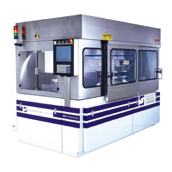
Strasbaugh Machine Description Figure 2-1 Model 6DS-SP Planarizer - Front View Control Panel Monitor and Keyboard Right Top Emergency Off Button Left Side Polish Section (Operator) Door Right Side Polish Section (Operator) Door Lower Left Front Service Door Lower Right Front Service Door Optional Fixed Remote Monitor Version 4.0 - February 1998... - Page 67 Operations Model 6DS-SP Planarizer The Right Top Emergency Off Button (3) is an emergency off switch, used for instantly stopping all machine motion and turning off control power at any time. The Control Panel (1) and Monitor and Keyboard (2), are described in detail later in this chapter.
-
Page 68: Figure 2-2 Planarizer Left Side View
Strasbaugh Machine Description Figure 2-2 Planarizer Left Side View Left Side Polish Section Operator Door (side view) Optional Fixed Remote Monitor And Control Panel Lower Left Front Service Door (side view) Left Side Service Door Right Side Electrical Cabinet (side view) -
Page 69: Figure 2-3 Planarizer Right Side View
Operations Model 6DS-SP Planarizer Figure 2-3 Planarizer Right Side View Right Side Polish Section Operator Door (side view) Operator Door Latch Assembly Lower Right Front Service Door (side view) Right Top Service Door Lower Right Side Service Door Left Side Electrical Cabinet (side view) -
Page 70: Planarizer Rear View
Strasbaugh Machine Description Figure 2-4 Planarizer Rear View Left Side Electrical Cabinet Service Door Right Side Electrical Cabinet Service Doors Rear Door Emergency Off Button Rear Door Power On Lamp Rear Electrical Enclosure Door Handle Main Power Supply Circuit Breaker Version 4.0 - February 1998... - Page 71 Operations Model 6DS-SP Planarizer The Left and Right Electrical Cabinets both have service doors. These doors must be closed and latched before the machine can be powered up. The Left Side Electrical Cabinet Service Door (19) must be completely closed to properly operate the door latch (23). The Rear Electrical...
-
Page 72: Planarizer Subassemblies
Strasbaugh Machine Description PLANARIZER SUBASSEMBLIES Figure 2-5, shown below, is a top view of the standard Model 6DS-SP Planarizer. (Refer to engineering drawing 217946U2.) The labeled subassemblies participate in the wafer polishing process and manipulation of the wafers. For a top view of the machine with a second polish table installed, refer to engineering drawing 225220U2. - Page 73 Operations Model 6DS-SP Planarizer The Bridge Assembly (1) encloses the Left and Right Spindle Drive Assemblies (2 and 3) and travels linearly left or right between the Load Stations (8 and 9) and the Polish Table (12). In Figure 2-5, the bridge is shown positioned over the polish table.
- Page 74 Strasbaugh Machine Description The Robot Assembly (6) transfers wafers from the send elevator cassettes to the load stations and from the load stations to the receive elevator cassettes. The Shuttle Assembly (7) travels forward and backward to position either the load stations or cleaning stations under the spindles.
-
Page 75: Control Panel And Emergency Off Buttons
A component’ s function remains the same regardless of its location. The control panel is located on the Model 6DS-SP Planarizer at the top center front of the machine. Figure 2-6 shows the layout of the panel components. A description of each component follows the figure. - Page 76 (such as a plugged drain pan). The alarm accompanies the error message displayed on the monitor. Alarm parameters are discussed in detail in the Machine Setup chapter of the 6DS-SP Operations manual. Version 4.0 - February 1998...
-
Page 77: Additional Emergency Off Buttons
Model 6DS-SP Planarizer ADDITIONAL EMERGENCY OFF BUTTONS The 6DS-SP is equipped with a minimum of four EMERG OFF (emergency off) pushbuttons. Additional buttons may be added, depending upon customer specifications. If the Mobile Remote Unit (SA 219187) is connected to the 6DSSP, the Mobile Remote E.M.O. -
Page 78: Control Computer
Machine Description CONTROL COMPUTER The section below introduces the control computer and provides an illustration of each of the sixteen 6DS-SP 4.25 software menus. WHERE TO FIND MORE INFORMATION ON THE SOFTWARE... For a detailed introduction to the 4.25 software, refer to the Operator Functions chapter of the 6DS-SP Operations manual. -
Page 79: Monitors And Keyboards
KEYBOARDS Two keyboards are available with the 6DS-SP, a flat panel mounted on the bezel of the monitor or a PC (personal computer) style enhanced keyboard. Either keyboard cable plugs into the extender cable connection centrally located on top of the machine cabinet. -
Page 80: Menus
Strasbaugh Machine Description MENUS The section below lists the 16 6DS-SP menus together with references for locating further information on each. For detailed information on the 6DS-SP software user interface, refer to the Operator Functions chapter of the 6DS-SP Operations manual. - Page 81 Every system involved with wafer handling may be manipulated individually at this menu. For further information, refer to the Software Calibration chapter of the 6DS-SP Maintenance manual. Diagnostics Menu All inputs, all outputs, all flags, and many counters may be viewed at this menu.
- Page 82 For further information, refer to the Software Calibration chapter of the 6DS-SP Maintenance manual. Homing Menu The machine is homed at this menu. For further information refer to the Operator Functions chapter of the 6DS-SP Operations manual.
-
Page 83: Mechanical Description
Operations Model 6DS-SP Planarizer MECHANICAL DESCRIPTION The section below provides descriptions of the mechanical assemblies and components participating in the auto polish cycle functions. BRIDGE DRIVE ASSEMBLY The bridge assembly encloses and supports the left and right spindle assemblies and their associated hardware. The bridge assembly moves the wafer carriers between the load stations and the polish table;... -
Page 84: Elevator Assembly
Strasbaugh Machine Description ELEVATOR ASSEMBLY The elevator assembly, located at the left of the machine, consists of two functional units, send and receive. The left and right send elevators, located at the rear of the machine, raise and lower cassettes loaded with unprocessed wafers. - Page 85 Operations Model 6DS-SP Planarizer When the elevator access door is closed, the elevator automatic fill and drain valve feature automatically keeps the elevator tanks filled with water whenever cassettes are present on the elevators. If an elevator arm is lifted, its tank will begin draining.
-
Page 86: Robot Assembly
Strasbaugh Machine Description ROBOT ASSEMBLY Supported by a slide assembly, the robot travels between the left elevators and the right load station, stopping at each elevator and load station (a range of approximately three feet). The slide assembly is comprised of two hardened steel rails and a lead screw supported at both ends. -
Page 87: Left/Right Load/Unload Stations
Operations Model 6DS-SP Planarizer LEFT/RIGHT LOAD/UNLOAD STATIONS Each load station is equipped with a load chuck mounted on an air cylinder (which raises and lowers the chuck). The load chuck takes vacuum on a wafer through vacuum ports. The load chuck lowers the wafer into the centering ring which has beveled sides to aid in centering the wafer in the ring. -
Page 88: Shuttle Assembly
The brushless DC servo motor is speed controlled by a servo controller, discussed in detail in the Control System Description chapter of the 6DS-SP Maintenance manual. The motor is bolted directly to the worm gear reduction gearbox. The gearbox is mounted to a box beam of the machine's framework along the backside and to an angled support beam at the front. -
Page 89: Spindle Drive Assembly
Operations Model 6DS-SP Planarizer A velocity command signal from the control computer instructs the velocity controller to ramp the motor up to the programmed speed. The gearbox turns the shaft, subtable, and granite table all as one unit, accelerating to constant speed. - Page 90 Strasbaugh Machine Description The wafer carrier mounting assembly has a flat underside with an aluminum chuck equipped with 0 rings. The 0 rings form two vacuum chambers between the chuck and the carrier. An applied vacuum source evacuates air from one chamber to firmly attach the wafer carrier to the spindle drive assembly.
-
Page 91: Spindle Down Force Assembly
Operations Model 6DS-SP Planarizer SPINDLE DOWN FORCE ASSEMBLY The spindle raise force assembly function is determined by springs located inside the raise force air cylinder. The springs move the piston which retracts the air cylinder rod, pulling on the back end of the lever arm. The lever then raises the spindle. -
Page 92: Conditioning Arm Down Force Assembly
Strasbaugh Machine Description CONDITIONING ARM DOWN FORCE ASSEMBLY The servo-controlled conditioning arm down force feature provides programmable down force for the pad conditioning device. The conditioning arm device assembly consists of a circular rotating device (with programmable rotational speed) which applies a downward force upon... -
Page 93: Facilities Connections
Operations Model 6DS-SP Planarizer FACILITIES CONNECTIONS The section below describes the utility sources required for 6DS-SP operation and procedures for making utility and slurry connections to the machine. CONFIRMING THAT UTILITY SOURCES MEET REQUIREMENTS IMPORTANT: The necessary utilities must meet the required specifications (shown below) in order for the Model 6DS-SP Planarizer to operate correctly. -
Page 94: General Facilities And Electrical Service Data Sheet
Strasbaugh Machine Description GENERAL FACILITIES AND ELECTRICAL SERVICE DATA SHEET Version 4.0 - February 1998 2 - 35... -
Page 95: Connecting Utilities
Engineering drawing 217946A2 is an accurate layout of the rear of a standard configuration 6DS-SP showing utility connections and plumbing. For a rear view of a B Model 6DS-SP, see drawing 225091A2. Assuming a standard machine configuration, Figure 2-7, below, is a simplified expanded view of the rear of the machine illustrating the location of utility connections and plumbing. - Page 96 Strasbaugh Machine Description Figure 2-7 Utility Connections - Standard Configuration Compressed Air Supply Loader Drain Slurry 1 Supply D. I. Water In Slurry 2 Supply D. I. Water Return Exhaust Coolant In Vacuum Coolant Bypass Coolant Out Main Machine Circuit Breaker...
-
Page 97: Electrical
Operations Model 6DS-SP Planarizer ELECTRICAL Related Engineering Drawings • 217946EK Small Electrical Subpanel (physical layout of main machine circuit breaker) • 217946E1 Electrical Schematic WARNING: DO NOT attempt to turn on the main machine power switch until ALL machine utilities are connected and all shipping brackets and tie wraps are removed. -
Page 98: Compressed Air
Strasbaugh Machine Description After making the electrical supply connection, leave the main power disconnect (main machine circuit breaker) in the "OFF" condition by moving the lever to its down position; close the electrical cabinet enclosure door and latch assembly tightly. -
Page 99: Vacuum Separator
Operations Model 6DS-SP Planarizer VACUUM SEPARATOR Related Engineering Drawings • 219771A1 Vacuum System Assembly • 219771P1 Vacuum System Diagram EXHAUST The machine exhaust duct (4) connection is to a vacuum source rated at approximately 250 SCFM. A six-inch duct or hose is required to connect to the exhaust duct. -
Page 100: Drains
Refer to the Safety section in Chapter One of this manual for further information on slurry compounds and waste disposal. The Model 6DS-SP Planarizer has two drains, both clearly labeled and located at the rear. The drain connection for the polish table drain tub is labeled table drain (8). -
Page 101: Slurry System Connection
Slurry Tanks Rear View • 220014E1 Third Peristaltic Pump The Model 6DS-SP Planarizer incorporates two integral slurry systems. A third slurry pump is available as an option. Refer to the engineering drawings listed above and Figure 2-1 of the previous section, for the following discussion. - Page 102 Strasbaugh Machine Description The slurry supply connection is a large 1/2" tube connection located near the perimeter of the slurry cart cover with a stainless steel tube extending down toward the bottom center of the slurry reservoir. This line should be connected to the inlet port of the diaphragm pump.
-
Page 103: Auto Polish Cycle Operation - The Sequence Of Events
3. powered up, homed, and prepared for an auto cycle, per procedures found in the Operator Functions chapter of the 6DS-SP Operations manual. A. CASSETTE LOADING The operator: 1. -
Page 104: Wafer Loading Sequence
Strasbaugh Machine Description B. WAFER LOADING SEQUENCE The send elevator moves to Slot 1. The robot arm extends into the cassette. The robot vacuum is turned on and the robot Z travels from its top position to its bottom position. -
Page 105: Polish Cycle Sequence
Operations Model 6DS-SP Planarizer C. POLISH CYCLE SEQUENCE The spindles move down to the table. The polishing sequence begins. Step 1 timing begins with spindles rotating at the programmed speed. Spindle down force and back pressure on the wafer start to ramp up. -
Page 106: Wafer Unloading Sequence
Strasbaugh Machine Description D. WAFER UNLOADING SEQUENCE A test is done to make sure wafer(s) are on spindle(s). The bridge moves to its load position. If wafer cleaning is enabled: a. The shuttle moves back. b. The spindles move down into the cleaning stations. -
Page 107: Cassette Removal
For further details on cycle termination and choices available at the Auto Polish Cycle menu when no cycle is running, refer to the Operator Functions chapter of the 6DS-SP Operations manual. 2 - 48 Version 4.0 - February 1998... - Page 108 Introduction PERATOR UNCTIONS...
- Page 109 Strasbaugh Operator Functions Operator Functions • OVERVIEW • INTRODUCTION TO THE 6DS-SP VERSION 4.25 SOFTWARE • MENUS USED IN BASIC OPERATION • BASIC OPERATION • OPERATION USING MANUAL LOADING OF WAFERS • OPERATOR ROUTINE PREVENTIVE MAINTENANCE AND ASSOCIATED PROCEDURES •...
- Page 110 Operations Model 6DS-SP Planarizer OVERVIEW Messages Displayed on the Control Computer Screen Take Precedence! Assumptions INTRODUCTION TO THE 6DS-SP SOFTWARE Software Features Menu Grouping and Recipe Definition Menu Grouping Recipe Definition Calibration/Configuration Changes User Interface Description Screen Usage Keypad and Keyboard Usage...
- Page 111 Operation of a Carrier Cleaning Cycle Operation of a Spindle Flush Cycle Heater/Chiller Operation Heater/Chiller Control Unit and Temperature Display Water Temperature Display on the 6DS-SP Status CYCLE HALTING FUNCTIONS AND ASSOCIATED PROCEDURES Cycle Halt Button During Polishing Phase of Auto Polish Cycle During Robot Wafer Movement Phase of Auto Polish Cycle “Finish”...
- Page 112 Model 6DS-SP Planarizer OPERATOR FUNCTIONS OVERVIEW This chapter is designed to introduce the 6DS-SP control software and to provide step-by-step procedures to the machine operator for operating and maintaining the 6DS-SP on a daily basis. Actions to be taken by the operator are shown in numbered steps with computer commands printed in bold type.
- Page 113 INTRODUCTION TO THE 6DS-SP SOFTWARE Notes: This software is intended to support virtually all 6DS-SP options. Therefore, some options shown on menus may not apply to a specific machine. The 6DS-SP Version 2.0 manuals provide the keystroke by keystroke instructions required by pre-4.00 software versions for all tasks. While the detailed keystroke descriptions of that manual do not apply to later versions of software, the procedural goals are essentially unchanged.
- Page 114 Model 6DS-SP Planarizer SOFTWARE FEATURES The table below lists software features, the menu(s) at which it is found, and where in the 6DS-SP Operations and Maintenance manuals to find detailed information on the feature. Where to Find Details - Feature...
- Page 115 Strasbaugh Operator Functions Where to Find Details - Feature Menu(s) Manual Location(s) PROGRAMMABLE PAD Calibration/Configuration Operations: CONDITIONING ARM Menu • Ch. 4-Machine Setup CALIBRATION AND Sweep Parameters Menu Maintenance: SETUP Manual Control Menu • Ch. 9-Mechanical Maintenance: • Ch. 10-Software Calibration •...
- Page 116 Operations Model 6DS-SP Planarizer Where to Find Details - Feature Menu(s) Manual Location(s) LIGHT TOWER SUPPORT Operations: • Ch. 2-Machine Description • Ch. 3-Operator Functions Maintenance: • Ch. 2-Physical Description UNIVERSAL CASSETTE Calibration/Configuration Maintenance: SUPPORT Menu • Ch. 10-Software Calibration •...
-
Page 117: Figure 3-1 Menu Grouping
Strasbaugh Operator Functions MENU GROUPING AND RECIPE DEFINITION MENU GROUPING The menus are divided into five groups: • Operation • Process Setup (recipe) • Machine Setup (routinely changed machine setups that are not process related) • Maintenance • Miscellaneous Both the Slurry Flush Menu and Recipe Management Menu apply to operation and recipe setup. - Page 118 Operations Model 6DS-SP Planarizer RECIPE DEFINITION The recipe is defined as everything seen in the Slurry Flush Menu and everything in the "parameter" menus. (Note: With pre-4.00 software, only polish parameter values were saved as the recipe.) Since everything in these menus can affect processing in some way, they are now included in the recipe.
- Page 119 Strasbaugh Operator Functions CALIBRATION/CONFIGURATION CHANGES Reflecting a reorganization of the handling of calibration and configuration choices, the Calibration/Configuration Menu of Version 4.25 and later contains only technician level calibration variables and one-time machine configuration that would not be changed by an operator or engineer.
-
Page 120: Figure 3-2 User Interface - Parts Of The Screen
Operations Model 6DS-SP Planarizer USER INTERFACE DESCRIPTION Figure 3-2 User Interface - Parts of the Screen 3 - 12 Version 4.0 - February 1998... - Page 121 Strasbaugh Operator Functions SCREEN USAGE The screen is divided into dedicated areas which never move and are never hidden by anything else. Therefore, you can always expect to find the same screen items in the same positions. Figure 3-2: Note that Figure 3-2 calls out the parts of the screen, providing some detail on the function of each.
- Page 122 Model 6DS-SP Planarizer Status Variable Display Area: The status area, shown at the right side of all the 6DS-SP menu screens, displays the machine values in real time. The machine values are inputs from sensors that monitor downforce, speed of table 1 (and table 2, if installed), and the current draw of table 1.
- Page 123 Strasbaugh Operator Functions Idle State with "Screen Saver": If the machine is left idle (not busy doing anything and no keys or buttons pressed), it will go to an idle state after a predetermined idle delay. The predetermined idle delay is selectable from 1 minute on up as calibration variable 185.
-
Page 124: Figure
Operations Model 6DS-SP Planarizer KEYPAD AND KEYBOARD USAGE Figure 3-3 Keypad Keys Used For almost all operation the only keys used are: F1 through F10 Corresponds to choices showing on the bottom of screen. Numbers For number entry Decimal Minus sign... - Page 125 Strasbaugh Operator Functions Keypad (shown in Figure 3-3) All letters are upper case only. The function of the Shift key differs from the Shift on a standard keyboard. Characters in the upper right corner of a key are obtained by pressing the Shift key and the key of choice at the same time.
- Page 126 Operations Model 6DS-SP Planarizer USER INPUT Screen Function Key Labels and Function Keys: The screen function key labels along the bottom of the screen describe choices possible at the currently displayed menu. A choice is available if the password level permits it and the machine's operation permits it.
- Page 127 Operator Functions Password Permission Levels: Illustrations of the menu screens used in the 6DS-SP Operations and Maintenance manuals include the password permission level(s) required for changing the available menu selections. All selections are available for viewing at all password levels.
- Page 128 Operations Model 6DS-SP Planarizer LIGHT TOWER SUPPORT The 6DS-SP supports a three (red/green/yellow) light tower or a four (red/green/yellow/blue) light tower. Refer to Calibration Variables in the Appendices of the 6DS-SP Maintenance manual for configuration selections. Refer to electrical drawing 217946E7 for details on relays.
- Page 129 Strasbaugh Operator Functions The four light tower operates as shown below: Color Light On Light Blink Light Off Maint. Alarm. No maint or alarm. YELLOW Cycle halted. A port empty All ports filled. (cassette not physically present or cassette ready to be removed).
- Page 130 Operations Model 6DS-SP Planarizer MENU SELECTION The F9 key will display "Select Menu" any time a menu is showing. Pressing the F9 key will cause the menu area to go blank and present a selection of eight menus and an "OTHER" choice. The "OTHER" choice will show an alternate list of menus.
- Page 131 Strasbaugh Operator Functions Figure 3-4 Menu Selection Version 4.0 - February 1998 3 - 23...
- Page 132 Model 6DS-SP Planarizer MENUS USED IN BASIC OPERATION WARNING: DO NOT OPERATE A 6DS-SP WITH AN UNLOADED CARRIER IN THE MACHINE! A carrier which is loaded on a spindle may not clear an unloaded carrier sitting on a load or cleaning station.
- Page 133 Strasbaugh Operator Functions HOME MACHINE MENU The machine's servo systems are homed at this menu. If the programmable conditioning arm is installed, its choice and a Jog Arm choice will show. The Jog Arm choice should only be used to move the arm away from the bridge when the arm is interfering with the bridge.
-
Page 134: Figure 3-5 Home Machine Menu
Operations Model 6DS-SP Planarizer Figure 3-5 Home Machine Menu 3 - 26 Version 4.0 - February 1998... - Page 135 Strasbaugh Operator Functions Function Key Choices Available at the Home Machine Menu Key Label Function(s) "ALL" causes all axes to be homed. The axes will be homed in a particular sequence. As each axis is completed, its status will change from Not Referenced to Referenced.
- Page 136 Operations Model 6DS-SP Planarizer AUTO POLISH CYCLE MENU This menu provides most of the functions needed for normally operating the machine. A polishing cycle may be started when this menu is showing. Choices may be unavailable based on password level, machine parameter setup, and machine status.
- Page 137 Strasbaugh Operator Functions Function Key Choices Available at the Auto Polish Cycle Menu Key Label Function(s) "Finish Cycle" causes the machine to stop after the current cycle. Finish This choice can be toggled on and off. (Auto mode only.) Cycle Next "Next Step"...
- Page 138 Operations Model 6DS-SP Planarizer Key Label Function(s) Flush "Flush Spindles" Starts a long spindle flush cycle for both Spndls spindles. The flush sequence is much longer than that used during automatic operation. Avoid aborting the spindle flush sequence. Instead, always let the sequence finish to prevent leaving a quantity of water in the backpressure system.
- Page 139 Strasbaugh Operator Functions ODD WAFER POLISHING: This feature permits a machine set for dual spindle polishing to polish a single remaining (odd) wafer. This feature is applicable in the automatic (cassette to cassette) mode only. Odd Wafer Polish and Odd Wafer Time Adjust choices are available in the Machine Parameters Menu.
- Page 140 Operations Model 6DS-SP Planarizer DUAL TIME AND DUAL BACKPRESSURE ENTRY CHOICES: This feature eliminates the need for "double entry" of left and right time or left and right backpressure parameters if there is no need for them to be different.
- Page 141 Strasbaugh Operator Functions AUTO CYCLE FEATURES: Three Auto Cycle features are function key choices to the Auto Polish Menu. These features are controlled by the function keys Next Step, Start W/Load, and Start W/Unload in the Auto Polish Menu. Next Step immediately causes the end of the present polishing step and an advance to the next step.
- Page 142 Operations Model 6DS-SP Planarizer SLURRY FLUSH MENU This menu permits setting slurry flush parameters for cleaning the slurry delivery systems. In addition, a slurry flush cycle may be started when this menu is showing. If in the operator password level, all choices will be unavailable and the cursor will not show.
- Page 143 Strasbaugh Operator Functions Menu Item Descriptions at the Slurry Flush Menu Item(s) Function(s) Slurry System Slurry 1 Sets the Slurry 1 system to be flushed. Slurry 2 Sets the Slurry 2 system to be flushed. Both Sets both the Slurry 1 and 2 systems to be flushed.
- Page 144 Operations Model 6DS-SP Planarizer RECIPE MANAGEMENT MENU The Recipe Management Menu permits storing, retrieving, and deleting recipes. Up to 72 recipes can be stored. All recipe names will show. Note: If you are using the bezel keyboard, the Alpha key must be pressed to set the keyboard to "alpha"...
-
Page 145: Figure 3-8 Recipe Management Menu
Strasbaugh Operator Functions Figure 3-8 Recipe Management Menu Version 4.0 - February 1998 3 - 37... - Page 146 Operations Model 6DS-SP Planarizer Function Key Choices Available at the Recipe Management Menu Key Label Function(s) Moves the cursor up to a new recipe name. Move If already at top, the cursor will "wrap" to the bottom. Move Moves the cursor down to a new recipe name.
- Page 147 SUMMARY The list below is a summary of the procedures needed to start up the 6DS-SP and complete an auto polish cycle. The sections following provide detailed steps or appropriate references for each.
- Page 148 Operations Model 6DS-SP Planarizer 1 - POWER UP Follow the steps below to power up the machine: Operator Action Explanation/Screen Display Utilities Confirm that all facilities to the machine are ON. Operator/Service Doors Close all doors to the machine. <MACHINE ON>...
- Page 149 Strasbaugh Operator Functions 2 - PERFORM HOME SEQUENCE ROUTINE Before the machine is homed, the screen displays a “PERFORM HOME SEQUENCE” prompt. Notes: Whenever the “PERFORM HOME SEQUENCE” prompt appears, go to the Home Machine Menu and perform the home sequence. When the machine displays the home sequence prompt, it will not permit the running of an auto polish or slurry flush cycle until the home sequence is performed.
-
Page 150: Figure 3-9 Home Machine Menu
Operations Model 6DS-SP Planarizer Figure 3-9 Home Machine Menu 3 - 42 Version 4.0 - February 1998... - Page 151 Strasbaugh Operator Functions To perform the home sequence routine, which moves all parts of the machine into correct alignment for the auto polish cycle, select ALL at the Home Machine Menu: Operator Action Explanation/Screen Display <F1> Press the F5 key to select “ALL”.
- Page 152 Operations Model 6DS-SP Planarizer 3 - PLACE CARRIERS ON SPINDLES NOTICE: The procedure below is for single-table machines ONLY. For two-table machines, refer to “Carrier Loading and Unloading for Machines Equipped with a Second Polish Table”, located on page 3-85U.
-
Page 153: Figure 3-10 Auto Polish Cycle Menu
Strasbaugh Operator Functions Figure 3-10 Auto Polish Cycle Menu Version 4.0 - February 1998 3 - 45... - Page 154 Operations Model 6DS-SP Planarizer Select the carrier load function: Operator Action Explanation/Screen Display <F8> At the Auto Polish Cycle menu, press the F8 key to select “OTHER”, displaying the alternate function key list. <F1> Press the F1 key to select “Load Carriers”.
- Page 155 Strasbaugh Operator Functions 4 - RETRIEVE A STORED RECIPE As instructed by your supervisor or the process engineer, retrieve a stored recipe by following the steps shown below: Note: To set or confirm recipe parameters, follow the procedures found in the Machine Setup chapter of this manual.
- Page 156 Operations Model 6DS-SP Planarizer 5 - RUN AN AUTO POLISH CYCLE Assumptions - The procedures below were written with the assumptions that: • The operator has powered up the machine and performed the home sequence routine. • The operator has installed the polishing pad, wafer backings, and wafer template rings.
- Page 157 Strasbaugh Operator Functions Select the Auto Polish Cycle Menu: Operator Action Explanation/Screen Display <F9> Press the F9 key to choose “Select Menu”. <F1> Display the Auto Polish Cycle Menu by pressing the F1 key to select “Auto Cycle”. Screen displays the Auto Polish Cycle menu.
- Page 158 Operations Model 6DS-SP Planarizer Wet pad and carrier inserts: Open the Left Side Operator Door. Using the interior operator hand water sprayer: Wet the table pad evenly. Wet the carrier inserts carefully by spraying up inside the carrier. DO NOT direct spray up inside machine cabinet.
- Page 159 Strasbaugh Operator Functions OPERATION USING MANUAL LOADING OF WAFERS Follow the procedure below to manually load wafers during an auto polish cycle rather than using the automated wafer handling (cassette and elevator) system detailed in the Basic Operation section of this chapter (above).
- Page 160 Operations Model 6DS-SP Planarizer 1 - POWER UP Following the steps found in the Basic Operation section of this chapter, above, power up the machine. 2 - PERFORM HOME SEQUENCE ROUTINE Following the steps found in the Basic Operation section of this chapter, above, home the machine.
- Page 161 Strasbaugh Operator Functions 5 - RUN AN AUTO POLISH CYCLE USING THE “START WITH LOAD” FEATURE Select the Auto Polish Cycle Menu and choose Start With Unload: Operator Action Explanation/Screen Display <F9> Press the F9 key to choose “Select Menu”.
- Page 162 Operations Model 6DS-SP Planarizer Place wafer(s) on load chuck(s): Open Left Side Operator Door. Place wafer(s) on the load chucks (polish side down or per supervisor instructions). Note: Place wafers on the load chucks corresponding to the active carriers selected for use (left, right, both), per supervisor instructions.
- Page 163 This section provides a maintenance schedule and procedures for all maintenance to be performed by the machine operator. Regular operator preventive maintenance, together with the preventive maintenance detailed in the 6DS-SP Maintenance manual, significantly minimizes machine downtime. Notice: As a part of Operator Preventive Maintenance, the Operator is responsible for reporting any indications of abnormal operation.
- Page 164 Operations Model 6DS-SP Planarizer DAILY PREVENTIVE MAINTENANCE SCHEDULE Note: For 7-Day, 28-Day, and 180-Day maintenance schedules, refer to the Preventive Maintenance chapter of the 6DS-SP Maintenance manual SUBJECT ACTION • Slurry Lines * Operate Slurry Flush Cycle once each shift.
- Page 165 Strasbaugh Operator Functions SLURRY SYSTEM FLUSH The Slurry System Flush flushes the slurry lines with D.I. (deionized) water. The Slurry Flush cycle should be operated regularly to keep the lines flowing freely. The frequency of flushing depends on the length of idle machine periods.
-
Page 166: Figure 3-11 Slurry Flush Menu
Operations Model 6DS-SP Planarizer Figure 3-11 Slurry Flush Menu 3 - 58 Version 4.0 - February 1998... - Page 167 Strasbaugh Operator Functions To flush both slurry lines at once, select Both: Operator Action Explanation/Screen Display <F2> At the Slurry Flush Menu, press the F2 key until the highlight bar moves to the “Slurry System” line. <F3> Press the F3 key (“View the Choice”...
- Page 168 Operations Model 6DS-SP Planarizer <F4> When the desired number is displayed on the Flow Rate line, press the F4 key to select “Enter Choice”. <F2> Press the F2 key until the highlight bar moves to the “Flush Time” line. Enter the desired number of seconds (for example, “30”).
- Page 169 Strasbaugh Operator Functions REMOVAL OF CARRIERS FROM SPINDLES NOTICE: The procedure below is for single-table machines ONLY. For two-table machines, refer to “Carrier Loading and Unloading for Machines Equipped with a Second Polish Table”, located on page 3-85U. WARNING: Always follow the procedure below to remove carriers from spindles.
- Page 170 Operations Model 6DS-SP Planarizer Select the carrier unload function: Operator Action Explanation/Screen Display <F8> At the Auto Polish Cycle menu, press the F8 key to select “OTHER”, displaying the alternate function key list. <F2> Press the F2 key to select “Unload Carriers”.
- Page 171 Strasbaugh Operator Functions CONSUMABLE MATERIALS SERVICING POLISHING PAD REMOVAL AND INSTALLATION Removal Turn machine power ON and perform home sequence: Following procedures detailed above, power up the machine and perform the home sequence routine. Remove table pad and clean table: Open the Right Side Operator Door.
- Page 172 Operations Model 6DS-SP Planarizer Clean and dry the table with a soft cloth: a. Feel the table by hand for adhesive residue. b. Remove remaining residue with mild solvent. c. Dry with soft cloth. Installation Install the new pad: Place a new pad on the clean table (backing side down) and center it.
- Page 173 Strasbaugh Operator Functions WAFER BACKING INSERT CHANGE Turn machine power ON and perform home sequence: Following procedures detailed in the Basic Operation section above, power up the machine and perform the home sequence routine. Remove carriers from spindles: Following procedures detailed above in this chapter, remove the carriers from spindles.
- Page 174 Operations Model 6DS-SP Planarizer Install new pad on each carrier: Install the two insert alignment pins (supplied by Strasbaugh with the machine) in the two alignment holes--one on each side of the carrier bottom. Place a new pad on the carrier bottom (backing side down) and align its two notches with the alignment pins.
- Page 175 Strasbaugh Operator Functions WAFER TEMPLATE RING CHANGE Tools Required • flatblade screwdriver • torque screwdriver Turn machine power ON and perform home sequence: Following procedures detailed in the Basic Operation section above, power up the machine and perform the home sequence routine.
- Page 176 Operations Model 6DS-SP Planarizer Install a new template ring on each carrier: Lay a new template ring on the carrier lip. Replace the clamp ring. Replace the eight 10-32 clamp screws, rotating them clockwise to snug. Using a torque screwdriver, tighten each of the eight clamp...
- Page 177 Strasbaugh Operator Functions OPERATION OF A TABLE CONDITIONING CYCLE USING THE CONDITIONING ARM Follow the procedure below to condition the table by running a pad conditioning cycle at the Auto Polish Menu. SUMMARY Power Up. Perform Home Sequence Routine. Retrieve a Stored Recipe.
- Page 178 Operations Model 6DS-SP Planarizer POWER UP Following the steps found in the Basic Operation section of this chapter, above, power up the machine. PERFORM HOME SEQUENCE ROUTINE Following the steps found in the Basic Operation section of this chapter, above, home the machine.
- Page 179 Strasbaugh Operator Functions RUN A PAD CONDITIONING CYCLE AT THE AUTO POLISH MENU Select the Auto Polish Cycle Menu and choose Condition Pad: Operator Action Explanation/Screen Display <F9> Press the F9 key to choose “Select Menu”. <F1> Display the Auto Polish Cycle Menu by pressing the F1 key to select “Auto Cycle”.
- Page 180 Operations Model 6DS-SP Planarizer OPERATION OF A TABLE CONDITIONING CYCLE WITH CONDITIONING DEVICES ON THE SPINDLES Follow the procedure below to condition the table by running an auto polish cycle with pad conditioning devices mounted on the spindles. SUMMARY The list below is a summary of the procedures needed to start up the machine and complete a table conditioning cycle using pad conditioning devices mounted on the spindles.
- Page 181 Strasbaugh Operator Functions Assumptions - The procedures below were written with the assumptions that: • The operator has read the Basic Operation section of this chapter (above). • The operator has installed the polishing pad. (See the Operator Routine Maintenance section, below, for procedures).
- Page 182 Operations Model 6DS-SP Planarizer RUN AN AUTO POLISH CYCLE Select the Auto Polish Cycle Menu and run an auto cycle: Operator Action Explanation/Screen Display <F9> Press the F9 key to choose “Select Menu”. <F1> Display the Auto Polish Cycle Menu by pressing the F1 key to select “Auto...
- Page 183 Strasbaugh Operator Functions OPERATION OF A CARRIER CLEANING CYCLE Note: Carrier cleaning is available on single table machines only. Repeat the procedure for Operation of a Table Conditioning Cycle Using the Conditioning Arm, above, making the following substitutions: • Load a recipe with carrier cleaning enabled. (Carrier cleaning parameters are set at the Conditioning/Cleaning Parameters Menu.)
- Page 184 WATER TEMPERATURE DISPLAY ON THE 6DS-SP STATUS The 6DS-SP control program continuously monitors cooling water in and out temperature and displays the readings in real time in the status area of the 6DS-SP menu screens.
- Page 185 Strasbaugh Operator Functions CYCLE HALTING FUNCTIONS AND ASSOCIATED PROCEDURES This section details the results of interrupting machine function by pressing the CYCLE HALT button; selecting “Abort/Reset” at any menu) to abort an auto polish cycle or other machine motion; selecting “Finish Cycle” at the Auto Polish Cycle Menu;...
- Page 186 Operations Model 6DS-SP Planarizer CYCLE HALT BUTTON DURING POLISHING PHASE OF AUTO POLISH CYCLE Operator Action/ Result(s)/ Location When Resolution × Press CYCLE HALT During polishing phase • All rotational button. of Auto Polish Cycle. movement stops, and spindles rise.
- Page 187 Strasbaugh Operator Functions “FINISH” AN AUTO POLISH CYCLE Operator Action/ Result(s)/ Location When Resolution × Choose “Finish Cycle” During Auto Polish • The finish cycle feature at the Auto Polish Cycle. causes automatic Cycle menu to select operation to end when...
- Page 188 Operations Model 6DS-SP Planarizer “ABORT” AN AUTO POLISH CYCLE OR OTHER MACHINE MOTION Operator Action/ Result(s)/ Location When Resolution × Press <F10> to select During Auto Polish • All rotational “Abort/Reset”. Cycle. movement stops, and spindles rise. Note: You must press <F10>...
- Page 189 Strasbaugh Operator Functions OPEN DOOR Operator Action/ Result(s)/ Location When Resolution × Open service door. During Auto Polish • All rotational Cycle. movement stops, and (Machine Cabinet) spindles rise. • Terminates Auto Polish Cycle. • Shuts down machine power. • Remove wafer(s) if...
- Page 190 Operations Model 6DS-SP Planarizer EMERG OFF BUTTON Operator Action/ Result(s)/ Location When Resolution × Press EMERG OFF At any time after • Shuts all power to the button. machine is powered up. machine down. (Control Panel) • All rotational movement stops, and spindles rise (if they are not already up).
- Page 191 Strasbaugh Operator Functions PROCEDURE FOR SAFE REMOVAL OF WAFER FROM ROBOT WHEN TO USE? Use the procedure below when machine power is still on but motion has been suspended (by pressing the CYCLE HALT button, opening a door, or “Aborting” at the Auto Polish Menu during a polishing cycle).
- Page 192 Operations Model 6DS-SP Planarizer Operator Action Explanation/Screen Display <F2> At the Manual Control Menu, press the F2 key to the highlight bar down to the “End Effector On/Off” line. <F3> Press the F3 key until “Off” is displayed. <F4> Press the F4 key to confirm turning robot end effector vacuum off.
- Page 193 SECOND POLISH TABLE Notes: As the 6DS-SP two-table machine design requires a fairly long reach to place carriers onto or remove them from the load stations, the carrier load fixture permits placement and removal of carriers with a reduced lift reach.
- Page 194 Operations Model 6DS-SP Planarizer With the flat side of the white plastic carrier load fixture facing up, place the fixture between the load station and the front of the machine. Confirm that the lip of the fixture engages with the front wall of the machine cabinet.
- Page 195 Strasbaugh Operator Functions Select the carrier load function: Operator Action Explanation/Screen Display 12. <F8> At the Auto Polish Cycle menu, press the F8 key to select “OTHER”, displaying the alternate function key list. 13. <F1> Press the F1 key to select “Load Carriers”.
- Page 196 Operations Model 6DS-SP Planarizer CARRIER UNLOADING FOR THE TWO-TABLE MACHINE WARNING: Always follow the procedure below to remove carriers from spindles. To prevent damage to table and spindles, DO NOT allow spindles to drop onto table. Tools Required • carrier load fixture (Symix # 274559) Procedure Close all doors to the machine.
- Page 197 Strasbaugh Operator Functions Select the carrier unload function: Operator Action Explanation/Screen Display <F8> At the Auto Polish Cycle menu, press the F8 key to select “OTHER”, displaying the alternate function key list. <F2> Press the F2 key to select “Unload Carriers”.
- Page 198 Operations Model 6DS-SP Planarizer 13. Lift the carrier out of the machine. 14. To unload a second carrier, repeat Steps 10., 11., 12., and 13., immediately above. 15. Remove the fixture. Note: To avoid damage to the machine, always remove the fixture before beginning any other procedure.
- Page 199 • Although repeated in the Cleaning Stations section of Chapter 11, Pneumatic Adjustments, of the 6DS-SP Maintenance manual as #4 in the Cleaning Station Adjustment Series, the cleaning station pad pressure adjustments detailed below are appropriate process procedures.
- Page 200 Operations Model 6DS-SP Planarizer CYLINDER PRESSURE / PAD FORCE TABLE The table below displays approximate pad forces for corresponding cylinder gauge pressure values. To achieve a specified pad force, following the procedure detailed in this section, set the cleaning station cylinder pressure at the associated value.
- Page 201 Strasbaugh Operator Functions Left Cleaning Station Pad Pressure Tools Required none PROCEDURE FOR SETTING PRESSURE Turn the machine power to OFF by pressing the red <EMERG OFF> button located on the control panel. Remove the Left Front Service Door. Find the pneumatic regulator positioned under Solenoid 2 of the valve panel located inside the Left Front Service Door.
- Page 202 Operations Model 6DS-SP Planarizer This page intentionally left blank. 3 - 94 Version 4.0 - February 1998...
- Page 203 Introduction ACHINE ETUP...
- Page 204 Strasbaugh Machine Setup Machine Setup • OVERVIEW • SLURRY FLUSH MENU • RECIPE MANAGEMENT MENU • (AUTO) POLISH PARAMETERS MENU • SWEEP PARAMETERS MENU • CONDITIONING/CLEANING PARAMETERS MENU • MACHINE PARAMETERS MENU • ALARM PARAMETERS MENU • MACHINE SETUP MENU •...
- Page 205 Operations Model 6DS-SP Planarizer OVERVIEW Menu Grouping Recipe Definition and Process Setup “On the Fly” Recipe Parameter Changes Machine Setup SLURRY FLUSH MENU RECIPE MANAGEMENT MENU (AUTO) POLISH PARAMETERS MENU SWEEP PARAMETERS MENU CONDITIONING/CLEANING PARAMETERS MENU MACHINE PARAMETERS MENU ALARM PARAMETERS MENU...
- Page 206 OVERVIEW This chapter addresses the process setup (recipe), machine setup, and password menus of the 6DS-SP 4.25 control software. For details on using the 6DS-SP software interface, refer to the Operator Functions chapter of this manual. Note also that for user convenience some information in this chapter is repeated in the Operator Functions chapter.
-
Page 207: Figure 4-1 Menu Grouping
Operations Model 6DS-SP Planarizer Figure 4-1 Menu Grouping RECIPE DEFINITION AND PROCESS SETUP The recipe is defined as everything seen in the Slurry Flush Menu and everything in the "parameter" menus. (Note: With previous software, only polish parameter values were saved as the recipe.) Since everything in these menus can affect processing in some way, they are now included in the recipe. - Page 208 Strasbaugh Machine Setup “ON THE FLY” RECIPE PARAMETER CHANGES A number recipe parameter changes may now be made while the machine is operating. For example, past, present, or future polishing steps can be changed. If the current step's time is changed to a longer time than what has transpired, the remaining time showing will increase by the same amount as the increase.
- Page 209 Operations Model 6DS-SP Planarizer SLURRY FLUSH MENU This menu permits setting slurry flush parameters for cleaning the slurry delivery systems. In addition, a slurry flush cycle may be started when this menu is showing. If in the operator password level, all choices will be unavailable, and the cursor will not show.
-
Page 210: Figure 4-2 Slurry Flush Menu
Strasbaugh Machine Setup Figure 4-2 Slurry Flush Menu Version 4.0 - February 1998 4 - 7... - Page 211 Operations Model 6DS-SP Planarizer Menu Item Descriptions at the Slurry Flush Menu Item(s) Function(s) Slurry System Slurry 1 Sets the Slurry 1 system to be flushed. Slurry 2 Sets the Slurry 2 system to be flushed. Both Sets both the Slurry 1 and 2 systems to be flushed.
- Page 212 Strasbaugh Machine Setup RECIPE MANAGEMENT MENU The Recipe Management Menu permits storing, retrieving, and deleting recipes. Up to 72 recipes can be stored. All recipe names will show. Note: If you are using the bezel keyboard, the Alpha key must be pressed to set the keyboard to "alpha"...
-
Page 213: Figure 4-3 Recipe Management Menu
Operations Model 6DS-SP Planarizer Figure 4-3 Recipe Management Menu 4 - 10 Version 4.0 - February 1998... - Page 214 Strasbaugh Machine Setup Function Key Choices Available at the Recipe Management Menu Key Label Function(s) Move Moves the cursor up to a new recipe name. If already at top, the cursor will "wrap" to the bottom. Moves the cursor down to a new recipe name.
- Page 215 Operations Model 6DS-SP Planarizer (AUTO) POLISH PARAMETERS MENU The Auto Polish Parameters Menu permits entry of the polishing step parameters. At this menu you may also set the number of wafers to be polished and start an auto polish cycle without returning to the Auto Polish Menu. Thus, you may make polish parameter changes and start an auto cycle without ever having to exit this menu.
-
Page 216: Figure 4-4 Polish Parameters Menu
Strasbaugh Machine Setup Figure 4-4 Polish Parameters Menu Version 4.0 - February 1998 4 - 13... - Page 217 Operations Model 6DS-SP Planarizer FUNCTION KEY CHOICES AVAILABLE AT THE AUTO POLISH PARAMETERS MENU Key Label Function(s) Move "Move Up" moves the cursor up one item. If already at the top, will "wrap" to the bottom. Move "Move Down" moves the cursor down one item. If already at Down the bottom, will "wrap"...
- Page 218 Strasbaugh Machine Setup Menu Item Descriptions at the Auto Polish Parameters Menu Item Function(s) Step Number Steps 1 through 10 are for the primary polish table. Steps 11 through 20 are for the optional second table. Left Time Sets the polish time for the left spindle.
- Page 219 Operations Model 6DS-SP Planarizer Item Function(s) Bk Prs Ramp Sets the number of seconds for the backpressure to linearly ramp from the last step value to the next step value. Sets the spindle speed for polishing. Spindle Speed Range: 0-250 rpm Sets the table speed for polishing.
- Page 220 Strasbaugh Machine Setup ADDITIONAL FEATURES PRESETTABLE WAFER POLISH COUNT: This feature permits the operator to set the machine to polish a finite number of wafers and stop automatically. Presettable Wafer Polish Count is applicable in the automatic (cassette to cassette) mode only.
- Page 221 Operations Model 6DS-SP Planarizer If the Left/Right choice is used, left and right parameter values can be entered separately. If the Matched choice is used, a value entered into either the left or right parameter will also be entered into the other. Also, a small bracket line to the left of the parameters will appear on both the Auto Polish Menu and the Polish Parameters Menu to indicate that new entries will be linked.
- Page 222 Strasbaugh Machine Setup SWEEP PARAMETERS MENU This menu permits setting parameters that determine how the programmable conditioning arm will sweep across the table. (The Conditioning/Cleaning Parameters Menu has other conditioning choices.) If the programmable arm is not installed, the Sweep Parameters Menu will not display.
-
Page 223: Figure 4-5 Sweep Parameters Menu
Operations Model 6DS-SP Planarizer Figure 4-5 Sweep Parameters Menu 4 - 20 Version 4.0 - February 1998... - Page 224 Strasbaugh Machine Setup FUNCTION KEY CHOICES AVAILABLE AT THE SWEEP PARAMETERS MENU Key Label Function(s) "Move Up" moves the cursor up one item in the present Move column. If already at the top will "wrap" to the bottom of that column.
- Page 225 Operations Model 6DS-SP Planarizer ADDITIONAL FEATURE PROGRAMMABLE ARM CALIBRATION AND SETUP: The optional programmable conditioning arm calibration and parameter setup is now used only to establish a park and table center position. The Conditioning Parameters Menu has choices that define the sweep endpoints in terms of inches from the table center.
- Page 226 Strasbaugh Machine Setup CONDITIONING/CLEANING PARAMETERS MENU (SCREEN PAGE 1) This menu/page permits setting some of the parameters that determine the pad conditioning cycle. Machines with the programmable arm can be set up for either pre or post polish conditioning or in-situ conditioning. If pre or post polish conditioning is selected (by not selecting in-situ conditioning), conditioning will occur between polish cycles.
- Page 227 Operations Model 6DS-SP Planarizer Figure 4-6 Conditioning/Cleaning Parameters Menu (Screen Page 1) 4 - 24 Version 4.0 - February 1998...
- Page 228 Strasbaugh Machine Setup Menu Item Descriptions at the Conditioning/Cleaning Parameters Menu (Screen Page 1) Item Function(s) Pad Conditioning Interval Sets how many polish cycles occur before each (ignored when in-situ conditioning) conditioning event. Conditioning Cycles Sets how many complete conditioning cycles will...
- Page 229 Operations Model 6DS-SP Planarizer Item Function(s) Slurry 1 Flow Rate Sets the flow rate for the Slurry 1 pump. (Ignored if fluid type not used for conditioning.) Range: 0-1000 ml/m Sets the flow rate for the Slurry 2 pump. Slurry 2 Flow Rate (Ignored if fluid type not used for conditioning.)
- Page 230 Strasbaugh Machine Setup CONDITIONING/CLEANING PARAMETERS MENU (SCREEN PAGE 2) This menu/page permits setting some of the parameters that determine the pad conditioning cycle, the wafer cleaning cycle, and the carrier cleaning cycle. Two table machines do not have the carrier cleaning or wafer cleaning choices.
-
Page 231: Figure 4-7 Conditioning/Cleaning Parameters Menu
Operations Model 6DS-SP Planarizer Figure 4-7 Conditioning/Cleaning Parameters Menu (Screen Page 2) 4 - 28 Version 4.0 - February 1998... - Page 232 Strasbaugh Machine Setup Menu Item Descriptions at the Conditioning/Cleaning Parameters Menu (Screen Page 2) Item Function(s) Sweep Stroke Style (ignored when in-situ conditioning) One Way The conditioning arm will sweep across the table and then lift for the return stroke for each conditioning cycle.
- Page 233 Operations Model 6DS-SP Planarizer Item Function(s) Carrier Cleaning Time (Single table machines only) Sets the time the carriers will be rotated and rinsed during cleaning. (Single table machines only) The cleaning device Carrier Cleaning Device will be raised against the carrier during cleaning.
- Page 234 Strasbaugh Machine Setup POLISH AND CONDITION FORCE UNITS AND DIAMETER ENTRY: Polish and conditioning force units and wafer diameter and conditioning device diameter are entered in the Machine Parameters Menu and Conditioning/Cleaning Parameters Menu respectively. This permits the units and diameters to be saved as part of the recipe.
- Page 235 Operations Model 6DS-SP Planarizer MACHINE PARAMETERS MENU (SCREEN PAGE 1 ) This menu/page permits setting the most commonly changed parameters for machine operation. (The other two screen pages for this menu contain parameters that are seldom changed.) These parameters can affect process and are therefore saved as part of the recipe.
- Page 236 Strasbaugh Machine Setup Figure 4-8 Machine Parameters Menu (Screen Page 1) Version 4.0 - February 1998 4 - 33...
- Page 237 Operations Model 6DS-SP Planarizer MENU ITEM DESCRIPTIONS AT THE MACHINE PARAMETERS MENU (SCREEN PAGE 1) Item Function(s) Auto Cycle Operation Sets wafer handling for fully automatic operation. Auto Sets wafer handling for manual wafer loading. Manual Used for spindle mounted conditioning devices.
- Page 238 Strasbaugh Machine Setup MACHINE PARAMETERS MENU (SCREEN PAGE 2) This menu/page permits setting some of the seldom changed parameters for machine operation. These parameters can affect process and are therefore saved as part of the recipe. (Other machine settings can be found in the Machine Parameters and Calibration/Configuration menus.)
- Page 239 Operations Model 6DS-SP Planarizer Figure 4-9 Machine Parameters Menu (Screen Page 2) 4 - 36 Version 4.0 - February 1998...
- Page 240 Strasbaugh Machine Setup Menu Item Descriptions at the Machine Parameters Menu (Screen Page 2) Item Function(s) Sets the carrier pad rinse and carrier top/side rinse Carrier Pad Rinse Time time after wafers are unloaded from spindles. Sets the load rinse time after wafers are unloaded Load Rinse Time from spindles.
- Page 241 Operations Model 6DS-SP Planarizer MACHINE PARAMETERS MENU (SCREEN PAGE 3) This menu/page permits setting some of the seldom changed parameters for machine operation. These parameters can affect process and are therefore saved as part of the recipe. (Other machine settings can be found in the Machine Parameters and Calibration/Configuration menus.)
-
Page 242: Figure 4-10 Machine Parameters Menu (Screen Page 3)
Strasbaugh Machine Setup Figure 4-10 Machine Parameters Menu (Screen Page 3) Version 4.0 - February 1998 4 - 39... - Page 243 Operations Model 6DS-SP Planarizer MENU ITEM DESCRIPTIONS AT THE MACHINE PARAMETERS MENU (SCREEN PAGE 3) Item Function(s) Load Rinse During Polish Load stations will be rinsed at intervals. Interval Load stations will be steadily rinsed. Steady Load stations will not be rinsed.
- Page 244 Strasbaugh Machine Setup ADDITIONAL FEATURES AT THE MACHINE PARAMETERS MENU DUAL TIME AND DUAL BACKPRESSURE ENTRY CHOICES: Polish Time Entry and Backpressure Entry choices are available in the Machine Parameters Menu. The choices are Left/Right or Matched. If the Left/Right choice is used, left and right parameter values can be entered separately.
- Page 245 Operations Model 6DS-SP Planarizer The Odd Wafer Time Adjust can be used to lengthen or shorten the polish times for the odd wafer polish cycle. All times for both tables will be multiplied by this value which is entered as a percent. 100 % is the nominal value and will cause no change to polish times.
- Page 246 Strasbaugh Machine Setup ALARM PARAMETERS MENU This menu permits entry of polish parameter alarm limits that are monitored during polishing. There is both a low and high limit for each polish parameter monitored. If any limit is exceeded, the alarm will sound and an error message will show and be logged into the error log.
-
Page 247: Figure 4-11 Alarm Parameters Menu
Operations Model 6DS-SP Planarizer Figure 4-11 Alarm Parameters Menu 4 - 44 Version 4.0 - February 1998... - Page 248 Strasbaugh Machine Setup MENU ITEM DESCRIPTIONS AT THE ALARM PARAMETERS MENU Item Function(s) Left Spindle Force Sets left spindle force alarm limits. Left Spindle Speed Sets left spindle speed alarm limits. Right Spindle Force Sets right spindle force alarm limits.
- Page 249 Operations Model 6DS-SP Planarizer ADDITIONAL FEATURES AT THE ALARM PARAMETERS MENU SLURRY ALARM ACTION CHOICE: Calibration variable 59 "Slry alrm action (0-no, l-yes)" permits assignment of certain action to the presence of an alarm indicating low or absent slurry. If set to "0", slurry alarms will display as information only.
- Page 250 Strasbaugh Machine Setup MACHINE SETUP MENU This menu/page permits changing machine settings that affect machine operation but not processing. Also, these are changes that are involved with normal machine operation. (Other "one time" settings are in the Calibration/Configuration menu.) If the machine does not have a scrubber station, the Use Scrubber choice should be set to Disable.
-
Page 251: Figure 4-12 Machine Setup Menu
Operations Model 6DS-SP Planarizer Figure 4-12 Machine Setup Menu 4 - 48 Version 4.0 - February 1998... - Page 252 Strasbaugh Machine Setup MENU ITEM DESCRIPTIONS AT THE MACHINE SETUP MENU Item Function(s) SECS Communication OffLine Disables the optional SECS communications. OnLine LOC Enables SECS with local machine control only. OnLine REM Enables SECS with remote machine control only. (However, Halt, Abort, and EMO will still work.)
- Page 253 Operations Model 6DS-SP Planarizer PASSWORD MENU This menu allows changing the password level, creating passwords, and deleting passwords. There are three password levels: "Operator", "Engineer", and "Maintenance". These levels determine which function key choices are available for each menu. The "Operator" level does not require a password and permits machine operation but not recipe changes or maintenance.
-
Page 254: Figure 4-13 Password Menu
Strasbaugh Machine Setup Figure 4-13 Password Menu Version 4.0 - February 1998 4 - 51... - Page 255 Operations Model 6DS-SP Planarizer Function Key Choices Available at the Password Menu Key Label Function(s) Set to "Set to Operator Level" causes the password level to be set to 'Oper' the most restrictive level. This does not require a password.
- Page 256 Strasbaugh Machine Setup ADDITIONAL FEATURES AT THE PASSWORD MENU EXPANDED PASSWORD PROTECTION: Three password levels are offered: Operator, Engineer, and Maintenance. The Operator level permits recipe retrieval but does not permit any changes to any menus (with the exception of optional time and backpressure changes described below).
- Page 257 Operations Model 6DS-SP Planarizer This page intentionally left blank. 4 - 54 Version 4.0 - February 1998...
- Page 258 Introduction ROUBLESHOOTING...
- Page 259 Strasbaugh Troubleshooting Troubleshooting • OVERVIEW • ALARM LOG MENU • FREQUENTLY ENCOUNTERED PROBLEM CONDITIONS • ERROR MESSAGES AND ALARMS Version 4.0 - February 1998 5 - 1...
-
Page 260: Figure 5-1 Alarm Log Menu
Operations Model 6DS-SP Planarizer OVERVIEW ALARM LOG MENU Function Key Choices Available at the Alarm Log Menu FREQUENTLY ENCOUNTERED PROBLEM CONDITIONS Machine Won’ t Power Up Machine Won’ t Home Cycle Won’ t Start--Part A Cycle Won’ t Start--Part B... - Page 261 Strasbaugh Troubleshooting “LEFT SPINDLE SPEED LOW ALARM” - # 3 “LEFT SPINDLE SPEED HIGH ALARM” - # 4 “RIGHT SPINDLE SPEED LOW ALARM” - # 7 “RIGHT SPINDLE SPEED HIGH ALARM” - # 8 “TABLE TEMP LOW ALARM” - # 9 “TABLE TEMP HIGH ALARM”...
- Page 262 Operations Model 6DS-SP Planarizer “SLURRY 1 SUPPLY LOW OR ABSENT” - # 105 “SLURRY 2 SUPPLY LOW OR ABSENT” - # 106 “WFR NOT ON SPINDLE, abort or START clears” - #107 “LEAK DETECTION FAULT” - # 108 “WFR FOUND ON SPINDLE, abort clears” - # 109 “BRIDGE LUBE OIL LOW”...
- Page 263 Strasbaugh Troubleshooting “ROBOT UP/DN NOT ARRIVING AT TOP” - # 184 “ROBOT UP/DN NOT ARRIVING AT MIDDLE” - # 185 “ROBOT UP/DN NOT ARRIVING AT BOTTOM” - # 186 “ROBOT UP/DN NOT ARRIVING AT ABOVE LOAD” - # 187 “ROBOT UP/DN NOT ARRIVING AT LEFT LOAD” - # 188 “ROBOT UP/DN NOT ARRIVING AT RIGHT LOAD”...
-
Page 264: Overview
The most effective means of preventing problems is careful adherence to all preventive maintenance schedules listed in the Preventive Maintenance chapter of the 6DS-SP Maintenance manual and the Operator Functions chapter of the 6DS-SP Operations manual. Messages Displayed on the Control Computer Screen Take Precedence! Messages and information displayed on the control computer screen always take precedence over information in this manual. - Page 265 Assumption The procedures below are discussed with the assumption that the reader is thoroughly familiar with the 6DS-SP Planarizer. If not, read the chapters in the Maintenance manual on Physical Description, Installation, Mechanical Description, Control System Description, Power Distribution, and Plumbing Description, as well as the Operator Functions and Machine Setup chapters of the 6DS-SP Operations manual, before beginning any procedure.
- Page 266 Operations Model 6DS-SP Planarizer ALARM LOG MENU The Alarm (Error) Log Menu logs the most recent 32 alarms which might indicate machine trouble. All alarms displayed on the screen are logged. The alarm log is intended for use as a troubleshooting aid. (It is not a machine history log.) If the machine is having a problem, this log may...
- Page 267 Strasbaugh Troubleshooting Figure 13-1 Alarm Log Menu Version 4.0 - February 1998 5 - 9...
-
Page 268: Function Key Choices Available At The Alarm Log Menu
Operations Model 6DS-SP Planarizer FUNCTION KEY CHOICES AVAILABLE AT THE ALARM LOG MENU Key Label Function(s) Page Up "Page Up" will cause the screen to go to a lower page number. If already on the lowest page (page 1), there will be no change. -
Page 269: Frequently Encountered Problem Conditions
Some problems show more than one unit responsible for resolution. Note: Refer to the Cycle Halt Functions section in the Operator Functions chapter of 6DS-SP Operations manual for details on what actually happens to the machine when the CYCLE HALT and EMERGENCY OFF buttons are pressed. -
Page 270: Machine Won' T Power Up
Operations Model 6DS-SP Planarizer MACHINE WON’ T POWER UP Problem Problem Component/ Cause Resolution/ Indicator Location Responsibility CONTROL Control Panel, (1) Facilities power (1a) Check to be sure PANEL LIGHT off. facilities power to Screen REMAINS OFF machine is ON. -
Page 271: Machine Won' T Home
Strasbaugh Troubleshooting MACHINE WON’ T HOME Problem Problem Component/ Cause Resolution/ Indicator Location Responsibility NO RESPONSE Monitor screen (1) Doors not (1a) Check and close closed. all doors. KEYBOARD “HOME” OPERATIONS COMMAND Version 4.0 - February 1998 5 - 13... -
Page 272: Cycle Won' T Start--Part A
Operations Model 6DS-SP Planarizer CYCLE WON’ T START--PART A Problem Problem Component/ Cause Resolution/ Indicator Location Responsibility NO RESPONSE No robot (1) Doors not (1a) Check and close TO PRESSING closed. all doors. movement; no CYCLE START machine BUTTON movement... -
Page 273: Cycle Won' T Start--Part B
Strasbaugh Troubleshooting CYCLE WON’ T START--PART B Problem Problem Component/ Cause Resolution/ Indicator Location Responsibility NO RESPONSE No robot (8) Shuttle assembly (8a) Check shuttle TO PRESSING not tripping position and movement; no CYCLE START machine forward reed adjustment. BUTTON movement switch. -
Page 274: Power Goes Off During Cycle
Operations Model 6DS-SP Planarizer POWER GOES OFF DURING CYCLE Problem Problem Component/ Cause Resolution/ Indicator Location Responsibility ALL LIGHTS Control Panel; (1) Service door(s) (1a) If robot is holding AND SCREEN open. wafer, carefully Monitor Screen DISPLAY GO remove wafer. (See... -
Page 275: Machine Halts During Cycle With Power Still On But Motion Suspended - Part A
Strasbaugh Troubleshooting MACHINE HALTS DURING CYCLE WITH POWER STILL ON BUT MOTION SUSPENDED - PART A Problem Problem Component/ Cause Resolution/ Indicator Location Responsibility MACHINE Interior of (1) Cycle paused-- (1a) If needed, close LIGHTS AND machine (suspended) operator door. -
Page 276: Machine Halts During Cycle With Power Still On But Motion Suspended - Part B
Operations Model 6DS-SP Planarizer MACHINE HALTS DURING CYCLE WITH POWER STILL ON BUT MOTION SUSPENDED - PART B Problem Problem Component/ Cause Resolution/ Indicator Location Responsibility MACHINE Interior of (2) Cycle (2a If robot is holding LIGHTS AND machine terminated by:... -
Page 277: Water Sprayer Won' T Spray
Strasbaugh Troubleshooting WATER SPRAYER WON’ T SPRAY Problem Problem Component/ Cause Resolution/ Indicator Location Responsibility WATER Interior of (1) Facilities water (1a) Check facilities SPRAYER off. water. machine. WON’ T SPRAY OPERATIONS (2) Failed solenoid (2a) Check and replace valve. -
Page 278: Elevator Tanks Won' T Hold Water
Operations Model 6DS-SP Planarizer ELEVATOR TANKS WON’ T HOLD WATER Problem Problem Component/ Cause Resolution/ Indicator Location Responsibility ELEVATOR Elevator tanks Manual Drain Manual Drain Valve: TANKS WON’ T Valve: HOLD WATER (1a) Close elevator (1) Elevator drain drain valve after valve not closed. -
Page 279: Wafers Left On Table - Part A
Strasbaugh Troubleshooting WAFERS LEFT ON TABLE - PART A Problem Problem Component/ Cause Resolution/ Indicator Location Responsibility WAFERS LEFT Table (1) Inadequate (1a) Check and restore ON TABLE AT vacuum. facility vacuum supply END OF AUTO to installation CYCLE specification. -
Page 280: Wafers Left On Table - Part B
Operations Model 6DS-SP Planarizer WAFERS LEFT ON TABLE - PART B Problem Problem Component/ Cause Resolution/ Indicator Location Responsibility WAFERS LEFT Table (4) Spindles and (4a) Realign spindles ON TABLE AT load stations and load stations. END OF AUTO misaligned. -
Page 281: Wafers Break During Polish Cycle - Part A
Strasbaugh Troubleshooting WAFERS BREAK DURING POLISH CYCLE - PART A Problem Problem Component/ Cause Resolution/ Indicator Location Responsibility WAFER Table 1) Debris on (1a) Press the EMERG BREAKS carrier. OFF button. DURING POLISH (1b) Remove wafers. CYCLE (1c) Remove debris from carriers. -
Page 282: Wafers Break During Polish Cycle - Part B
Operations Model 6DS-SP Planarizer WAFERS BREAK DURING POLISH CYCLE - PART B Problem Problem Component/ Resolution/ Indicator Location Cause Responsibility WAFER Table (4) Spindles and (4a) Realign spindles BREAKS load stations and load stations. DURING misaligned. POLISH CYCLE (5) At the... -
Page 283: Carriers Drop Off Spindles
See the Pneumatic Adjustments chapter and the information on the Diagnostics and Manual Control menus found in the Mechanical Maintenance Procedures chapter of the 6DS-SP Maintenance manual. MAINTENANCE (3) Vacuum (3a) Replace vacuum solenoid total solenoid failure-no response to adjustment. -
Page 284: Robot Drops Wafers--Part A
(4) Incorrect robot Z alignment at the (4a) Recalibrate by load stations. performing “Robot Z- Axis Load Station Position” calibrations, found in the Software Calibration chapter of the 6DS-SP Maintenance manual. MAINTENANCE 5 - 26 Version 4.0 - February 1998... -
Page 285: Robot Drops Wafers--Part B
Manual Control menus found in the Mechanical Maintenance Procedures chapter of the 6DS-SP Maintenance manual. MAINTENANCE (5a) Notes on Adjusting Load Chuck Surface to Parallel with Robot Arm: • For machines equipped with load chuck jack screws, adjust the jack screws to correct the load chuck position. - Page 286 Operations Model 6DS-SP Planarizer ** (6a) Notes on Testing and Adjusting Vacuum Solenoid: At Page 1 of the Manual Control Menu, select End Effector On/Off and choose On to turn vacuum ON to the robot vacuum chuck. Manually hold a test wafer under the robot vacuum chuck to see if the chuck can take the wafer.
-
Page 287: Software (Computer) Problems
Strasbaugh Troubleshooting SOFTWARE (COMPUTER) PROBLEMS NO RESPONSE FROM KEYBOARD OR NO RESPONSE FROM MACHINE--PART A Problem Problem Component/ Resolution/ Indicator Location Cause Responsibility Monitor screen. (1) Keyboard not (1a) Connect RESPONSE connected. keyboard. FROM KEYBOARD (2)Control (2a)Press the program EMERG OFF... -
Page 288: No Response From Keyboard Or No Response From Machine--Part B
Operations Model 6DS-SP Planarizer NO RESPONSE FROM KEYBOARD OR NO RESPONSE FROM MACHINE--PART B Problem Problem Component/ Resolution/ Indicator Location Cause Responsibility (3) If, after (3a) Follow completing procedures in the Resolutions 1a Software And through 1e, still Control Computer... -
Page 289: Error Messages And Alarms
(low limit) alarm conditions in percentage of error for ten machine functions. For more information on the Alarm Parameters Menu, refer to the Machine Setup chapter of the 6DS-SP Operations manual. Version 4.0 - February 1998 5 - 31... -
Page 290: Left Spindle Force Low Alarm
Operations Model 6DS-SP Planarizer “LEFT SPINDLE FORCE LOW ALARM” - # 1 “LEFT SPINDLE FORCE HIGH ALARM” - # 2 “RIGHT SPINDLE FORCE LOW ALARM” - # 5 “RIGHT SPINDLE FORCE HIGH ALARM” - # 6 PART A Problem Problem... -
Page 291: Left Spindle Force Low Alarm
Spindle Force Calibration procedure (per Maintenance manual). (3a) Perform the Spindle E-P Calibration, located in (3) Calibration of the Software E-P setting needed. Calibration chapter of the 6DS-SP Maintenance manual. MAINTENANCE Version 4.0 - February 1998 5 - 33... -
Page 292: Left Spindle Speed Low Alarm
Operations Model 6DS-SP Planarizer “LEFT SPINDLE SPEED LOW ALARM” - # 3 “LEFT SPINDLE SPEED HIGH ALARM” - # 4 “RIGHT SPINDLE SPEED LOW ALARM” - # 7 “RIGHT SPINDLE SPEED HIGH ALARM” - # 8 PART A Problem Problem... -
Page 293: Left Spindle Speed Low Alarm
Strasbaugh Troubleshooting “LEFT SPINDLE SPEED LOW ALARM” - # 3 “LEFT SPINDLE SPEED HIGH ALARM” - # 4 “RIGHT SPINDLE SPEED LOW ALARM” - # 7 “RIGHT SPINDLE SPEED HIGH ALARM” - # 8 PART B Problem Problem Component/ Cause... - Page 294 Operations Model 6DS-SP Planarizer “TABLE TEMP LOW ALARM” - # 9 “TABLE TEMP HIGH ALARM” - # 10 “TABLE SPEED LOW ALARM” - # 11 “TABLE SPEED HIGH ALARM” - # 12 Problem Problem Component/ Cause Resolution/ Indicator Location Responsibility ALARM Control Panel.
-
Page 295: Slurry 1 Flow Low Alarm
Strasbaugh Troubleshooting “SLURRY 1 FLOW LOW ALARM” - # 13 “SLURRY 1 FLOW HIGH ALARM” - # 14 “SLURRY 2 FLOW LOW ALARM” - # 17 “SLURRY 2 FLOW HIGH ALARM” - # 18 Problem Problem Component/ Cause Resolution/ Indicator... -
Page 296: Slurry 1 Ph Low Alarm
(2b) If the status area level displayed is not within the range of the alarm parameters, adjust the pH transmitter (refer to the Software Calibration chapter of the 6DS-SP Maintenance manual). MAINTENANCE 5 - 38 Version 4.0 - February 1998... -
Page 297: Conditioning Arm Position Error
Diagnostics menu. It should be: INPUT 22 - ON (3b) Perform the Conditioning Arm calibration procedures (refer to the Software Calibration chapter of the 6DS-SP Maintenance manual). MAINTENANCE Version 4.0 - February 1998 5 - 39... -
Page 298: Left Spindle Vacuum Switch Off
Operations Model 6DS-SP Planarizer “LEFT SPINDLE VACUUM SWITCH OFF” - # 51 “RIGHT SPINDLE VACUUM SWITCH OFF” - # 52 Problem Problem Component/ Cause Indicator Location Resolution ERROR Control (1) Carrier not (1a) Install carrier for MESSAGE installed. affected spindle. - Page 299 Strasbaugh Troubleshooting The servo controller notices that the bridge motor is not going where it is supposed to, assumes trouble, and turns off the motor in a control sense. The end result is an error such as “Bridge not arriving at load” showing, and a servo status with the motor off and the motor error on.
-
Page 300: Send Cassette(S) Not Active
Operations Model 6DS-SP Planarizer “SEND CASSETTE(S) NOT ACTIVE” - # 53 Problem Problem Component/ Cause Indicator Location Resolution ERROR Control (1) Control (1a) Place a cassette on MESSAGE Computer computer not a receive elevator. Screen finding active receive cassette. OPERATIONS (1b) Lower the cassette sensor arm. -
Page 301: Left Spindle Not Up
Strasbaugh Troubleshooting “LEFT SPINDLE NOT UP” - # 55 “RIGHT SPINDLE NOT UP” - # 56 Problem Problem Component/ Cause Indicator Location Resolution ERROR Control (1) Spindle not (1a) Check and adjust MESSAGE Computer tripping upper limit upper limit switch. - Page 302 Operations Model 6DS-SP Planarizer “AXIS 1 SERVO AMPLIFIER FAULT” - # 57 (LEFT SPINDLE) “AXIS 2 SERVO AMPLIFIER FAULT”- # 58 (RIGHT SPINDLE) “AXIS 3 SERVO AMPLIFIER FAULT” - #59 (BRIDGE TRAVEL) “AXIS 4 SERVO AMPLIFIER FAULT” - #60 (TABLE)
- Page 303 Strasbaugh Troubleshooting “ROBOT TRAVEL NOT HOMED” - # 63 Problem Problem Component/ Cause Indicator Location Resolution ERROR Control (1) Robot travel not (1a) Rehome the Axis 9 MESSAGE Computer homed. at the Servo Screen Initialization menu. OPERATIONS “ROBOT TOP AXIS NOT HOMED” - # 64...
-
Page 304: Bridge Travel Not Homed
Operations Model 6DS-SP Planarizer “ROBOT UP/DOWN AXIS NOT HOMED” - # 66 Problem Problem Component/ Cause Indicator Location Resolution ERROR Control (1) Robot Z not (1a) Rehome Axis 12 at MESSAGE Computer homed. the Servo Initialization Screen menu. OPERATIONS “WAFER FOUND ON ROBOT” - # 67... -
Page 305: Polish Section Operator Door Open At Start
Strasbaugh Troubleshooting “POLISH SECTION OPERATOR DOOR OPEN AT START” - # 69 (no alarm) Problem Problem Component/ Cause Indicator Location Resolution ERROR Control (1) Polish section (1a) Close door(s). MESSAGE Computer operator door(s) open. Screen OPERATIONS “ELEVATOR SECTION OPERATOR DOOR OPEN AT START ” - # 70... -
Page 306: Wafer At Left Snd Elevator
(refer to the Software Calibration chapter of the 6DS-SP Maintenance manual). (2a) Check that the robot end effector is correctly adjusted and (2) Robot end picking up wafers. -
Page 307: Slurry 1 Supply Low Or Absent
Strasbaugh Troubleshooting “TABLE DRAIN OVERFLOW FAULT” - # 104 Problem Problem Component/ Cause Indicator Location Resolution ERROR Control (1) Table drain (1a) Let cycle finish. MESSAGE Computer clogged. Screen (1b) Clean up spillage, if any. (1c) Clean out table drain basket. -
Page 308: Wfr Not On Spindle, Abort Or Start Clears" - #107
Operations Model 6DS-SP Planarizer “WFR NOT ON SPINDLE, ABORT OR START CLEARS” - #107 Note: “WFR NOT ON SPINDLE” and “WFR FOUND ON SPINDLE” are the only error conditions that will actually halt an auto cycle. Problem Problem Component/ Cause... -
Page 309: Leak Detection Fault
Strasbaugh Troubleshooting “LEAK DETECTION FAULT” - # 108 Problem Problem Component/ Cause Indicator Location Resolution ERROR Control (1) Fluid leak. (1a) Let cycle finish. MESSAGE Computer Screen Three pans at (1b) Clean up spillage. machine bottom (one at load area;... -
Page 310: Wfr Found On Spindle, Abort Clears
Operations Model 6DS-SP Planarizer “WFR FOUND ON SPINDLE, ABORT CLEARS” - # 109 Note: “WFR NOT ON SPINDLE” and “WFR FOUND ON SPINDLE” are the only error conditions that will actually halt an auto cycle. Problem Problem Component/ Cause Indicator... -
Page 311: Bridge Lube Oil Low
(1) Bridge (1a) Referring to the MESSAGE Computer Lubricator needs to Preventive Screen be refilled. Maintenance chapter of the 6DS-SP Maintenance manual, add the approved oil. MAINTENANCE “LOW COOLING WATER FLOW RATE” - # 111 Problem Problem Component/ Cause Indicator... -
Page 312: Air, Water, Or Vacuum Absent
Operations Model 6DS-SP Planarizer “AIR, WATER, OR VACUUM ABSENT” - # 112 Problem Problem Component/ Cause Indicator Location Resolution ERROR Control (1) Facility air, (1a) Verify facilities are MESSAGE Computer water, or vacuum Screen not on or below machine required (1b) Verify facilities set operating range. -
Page 313: Wfr Found On Load Station
Strasbaugh Troubleshooting “WFR FOUND ON LOAD STATION” - # 122 Problem Problem Component/ Cause Indicator Location Resolution ERROR Control (1) Wafer on load (1a) Manually remove MESSAGE Computer station. wafer and restart Screen cycle. OPERATIONS (2) Load station (2a) Adjust the load vacuum switch station vacuum switch. -
Page 314: Wafer Not Found At Right Load
Operations Model 6DS-SP Planarizer “WAFER NOT FOUND AT RIGHT LOAD” - # 143 “WAFER NOT FOUND AT LEFT LOAD” - # 144 Problem Problem Component/ Cause Indicator Location Resolution ERROR Control (1) Wafer not (1a) Verify wafer is MESSAGE Computer present. -
Page 315: Wafer Not Found On Robot
Strasbaugh Troubleshooting “WAFER NOT FOUND ON ROBOT” - # 149 Problem Problem Component/ Cause Indicator Location Resolution ERROR Control (1) Robot wafer (1a) Verify wafer is MESSAGE Computer sensor not sensing a present. Screen wafer when the vacuum is ON... - Page 316 Operations Model 6DS-SP Planarizer “TBL 2 NOT LOCKING (LEFT LOCK)” - # 152 “TBL 2 NOT LOCKING (RIGHT LOCK)” - # 153 “TBL 2 NOT UNLOCKING (LEFT LOCK)” - # 154 “TBL 2 NOT UNLOCKING (RIGHT LOCK)” - # 155...
- Page 317 Strasbaugh Troubleshooting “LEFT SPINDLE VACUUM NOT FOUND” - # 156 “RIGHT SPINDLE VACUUM NOT FOUND” - # 157 Problem Problem Component/ Cause Indicator Location Resolution ERROR Control (1) Carrier not (1a) Install carrier for MESSAGE installed. affected spindle. Computer Screen...
- Page 318 Operations Model 6DS-SP Planarizer “CONDITION ARM NOT ARRIVING UP” - # 158 “CONDITION ARM NOT ARRIVING DOWN” - # 159 Problem Problem Component/ Cause Indicator Location Resolution ERROR Control (1) Conditioning (1a) Verify machine MESSAGE Computer arm not arriving at...
-
Page 319: Right Spindle Not Arriving Up
Strasbaugh Troubleshooting “LEFT SPINDLE NOT ARRIVING UP” - # 160 “LEFT SPINDLE NOT ARRIVING UP” - # 161 “RIGHT SPINDLE NOT ARRIVING UP” - # 162 “RIGHT SPINDLE NOT ARRIVING UP” - # 163 Problem Problem Component/ Cause Indicator Location... - Page 320 Operations Model 6DS-SP Planarizer “LT SEND ELEV NOT ARRIVING AT SLOT - # 164 “RT SEND ELEV NOT ARRIVING AT SLOT - # 165 “LT RECV ELEV NOT ARRIVING AT SLOT - # 166 “RT RECV ELEV NOT ARRIVING AT SLOT - # 167...
- Page 321 Strasbaugh Troubleshooting “ROBOT NOT ARRIVING AT LEFT SEND” - # 171 “ROBOT NOT ARRIVING AT RIGHT SEND” - # 172 “ROBOT NOT ARRIVING AT LEFT RECV” - # 173 “ROBOT NOT ARRIVING AT RIGHT RECV” - # 174 “ROBOT NOT ARRIVING AT LEFT LOAD” - # 175 “ROBOT NOT ARRIVING AT LEFT LOAD”...
- Page 322 Operations Model 6DS-SP Planarizer “ROBOT ARM NOT ARRIVING AT ZERO” - # 177 “ROBOT ARM NOT ARRIVING AT LEFT SEND” - # 178 “ROBOT ARM NOT ARRIVING AT RIGHT SEND” - # 179 “ROBOT ARM NOT ARRIVING AT LEFT RECV” - # 180 “ROBOT ARM NOT ARRIVING AT RIGHT RECV”...
- Page 323 Strasbaugh Troubleshooting “BRIDGE NOT ARRIVING AT LEFT CURTAIN - # 190 “BRIDGE NOT ARRIVING AT RIGHT CURTAIN - # 191 Problem Problem Component/ Cause Indicator Location Resolution ERROR Control (1) Bridge servo not (1a) Servo tripped out-- MESSAGE Computer arriving at the...
- Page 324 Operations Model 6DS-SP Planarizer “WAFER NOT SEATING AT LEFT LOAD” - # 197 “WAFER NOT SEATING AT RIGHT LOAD” - # 198 Problem Problem Component/ Cause Indicator Location Resolution ERROR Control (1) The load chuck (1a) Wafer absent or MESSAGE...
- Page 325 Strasbaugh Troubleshooting “POLISH SECTION OPERATOR DOOR OPEN” - #199 (no alarm) Problem Problem Component/ Cause Indicator Location Resolution ERROR Control (1) Polish section (1a) Close door(s). MESSAGE Computer operator door(s) open. Screen OPERATIONS “ELEVATOR SECTION OPERATOR DOOR OPEN” - # 200...
- Page 326 Introduction PPENDICES...
- Page 327 Strasbaugh, Inc. Appendices Appendices • Appendix A Electrical Input/Output System Address List Refer To Engineering Drawing 217946EM Version 4.0 - January 1, 1998...
- Page 328 Operations Model 6DS-SP Planarizer This page intentionally left blank. Version 4.0 - February 1998...
- Page 329 Introduction LECTRIAL NPUT UTPUT...
- Page 330 Strasbaugh Appendices Appendix A Electrical Input/Output System Address List: Refer To Engineering Drawing 217946EM Version 4.0 - February 1998...
- Page 331 Operations Model 6DS-SP Planarizer This page intentionally left blank.
- Page 333 These manuals will be replaced with Version 4.1 of the Model 6DSSP Operations and Maintenance Manuals (combined) when they are available. If you have not received the replacement manuals by February 1, 2002, please contact your local Strasbaugh representative. Thank you for your patience, Strasbaugh Technical Publications...
- Page 334 Model 6DS-SP Planarizer Maintenance Manual VOLUME 1 STRASBAUGH 825 Buckley Road San Luis Obispo, California 93401 Phone: (805) 541-6424 Fax: (805) 541-6425...
- Page 335 Copyright © 1998 by Strasbaugh. All rights reserved. Document prepared by: Technical Publications Group...
- Page 336 Volume One Chapter 1 Introduction WHAT’ S NEW..Flat Panel Display Operator Interface Version 4.25 of the 6DS-SP Software Revised, Updated Engineering Drawings 6DS-SP User Interface Reference Document Addition ABOUT THE 6DS-SP MANUALS Operations Manual - Contents and Purpose Maintenance Manual - Contents and Purpose...
- Page 337 Maintenance Model 6DS-SP Planarizer Chapter 2 Installation Overview Summary Step 1 - Obtain the Facility and Equipment Preparation Sign-Off Sheet Step 2 - Unpacking and Inspection Preparation for Installation Step 3 - Machine Placement Step 4 - Leveling Leveling Requirement...
- Page 338 Strasbaugh Table of Contents Flat Panel Display Operator Interface, Keypad, and Keyboard Keypad and Keyboard Menus Chapter 4 Mechanical Description Overview Auto Polish Cycle Operation - The Sequence of Events Cassette Loading Wafer Loading Sequence Polish Cycle Sequence Wafer Unloading Sequence...
- Page 339 Maintenance Model 6DS-SP Planarizer Chapter 6 Power Distribution Introduction AC Distribution DC Distribution Power Up Interlocks Chapter 7 Plumbing Description Compressed Air System Vacuum System Water System Exhaust System Slurry System Chemical System Drain System Chapter 8 Preventive Maintenance Schedules...
- Page 340 Strasbaugh Table of Contents Chapter 9 Mechanical Maintenance OVERVIEW Order of Adjustment Menus Used in the Mechanical Maintenance Procedures Running a Short Test Cycle CARRIERS Changing Wafer Backing Inserts Assembly and Disassembly of a Carrier Assembly of a Carrier Disassembly of a Carrier...
- Page 341 Maintenance Model 6DS-SP Planarizer Tables Polish Table Removal and Installation Removal Installation Table Alignment Mechanical Maintenance Procedures for the Second Table Option Removal of Electrical Power for the Second Table at the Terminal Block Measurement of the Present Load Chuck Height Position...
- Page 342 Strasbaugh Table of Contents Programmable Arm Calibration [#4 in Conditioning Arm Adjustment Series] Controllable Conditioning Down Force Option Calibration [#5 in Conditioning Arm Adjustment Series] ELEVATORS AND ROBOT--ORDER OF ADJUSTMENT ELEVATORS Elevator Height Calibration [#4 in Elevators and Robot Adjustment Series]...
- Page 343 Backing Up Polish Recipes and Machine Data Files Restoring Polish Recipes and Machine Data Files Other Useful Software Procedures Exiting to the DOS System Prompt from the 6DS-SP Control Program Menus Formatting Diskettes Starting the 6DS-SP Control Program at the DOS Prompt 6DS-SP Date and Time Setting Version 4.0 - February 1998...
- Page 344 Strasbaugh Table of Contents Chapter 13 Troubleshooting 13-1 OVERVIEW ALARM LOG MENU Function Key Choices Available at the Alarm Log Menu FREQUENTLY ENCOUNTERED PROBLEM CONDITIONS Machine Won’ t Power Up Machine Won’ t Home Cycle Won’ t Start--Part A Cycle Won’ t Start--Part B...
- Page 345 Maintenance Model 6DS-SP Planarizer “LEFT SPINDLE SPEED LOW ALARM” - # 3 “LEFT SPINDLE SPEED HIGH ALARM” - # 4 “RIGHT SPINDLE SPEED LOW ALARM” - # 7 “RIGHT SPINDLE SPEED HIGH ALARM” - # 8 “TABLE TEMP LOW ALARM” - # 9 “TABLE TEMP HIGH ALARM”...
- Page 346 Strasbaugh Table of Contents “SLURRY 1 SUPPLY LOW OR ABSENT” - # 105 “SLURRY 2 SUPPLY LOW OR ABSENT” - # 106 “WFR NOT ON SPINDLE, abort or START clears” - #107 “LEAK DETECTION FAULT” - # 108 “WFR FOUND ON SPINDLE, abort clears” - # 109 “BRIDGE LUBE OIL LOW”...
- Page 347 Maintenance Model 6DS-SP Planarizer “ROBOT ARM NOT ARRIVING AT LEFT LOAD” - # 182 “ROBOT ARM NOT ARRIVING AT RIGHT LOAD” - # 183 “ROBOT UP/DN NOT ARRIVING AT TOP” - # 184 “ROBOT UP/DN NOT ARRIVING AT MIDDLE” - # 185 “ROBOT UP/DN NOT ARRIVING AT BOTTOM”...
- Page 348 Strasbaugh Table of Contents Volume Two Appendix A 6DS-SP Calibration Variables Listing 6DS-SP User Interface Reference Appendix B Engineering Drawings (bound under separate cover) Customer Parts Lists Appendix C Electrical Input/Output System Address List (Refer to engineering drawing 217946EM) Appendix D...
- Page 349 Maintenance Model 6DS-SP Planarizer Menu Information Locator The table below lists the 6DS-SP 4.25 software menus alphabetically together with the location(s) in the Operations and Maintenance manuals at which detailed information on each may be found. Menu Where to Find Details - Manual...
- Page 350 Strasbaugh Table of Contents Menu Where to Find Details - Manual Location(s) Polish Parameters (Recipe Management) Menu Operations: Ch. 3-Operator Functions Ch. 4-Machine Setup Slurry System Flush Menu Operations: Ch. 4-Machine Setup Sweep Parameters Menu Operations: Ch. 4-Machine Setup Version 4.0 - February 1998...
- Page 351 The Version 4.25 software introduces new features not available in previous software versions. The table below lists each feature, the menu(s) at which it is found, and where in the 6DS-SP Operations and Maintenance manuals to find detailed information on the feature.
- Page 352 Strasbaugh Table of Contents Where to Find Details - Feature Menu(s) Manual Location(s) Programmable Pad Calibration/Configuration Operations: Conditioning Arm Menu Ch. 4-Machine Setup Calibration and Setup Sweep Parameters Menu Maintenance: Manual Control Menu Ch. 9-Mechanical Maintenance: Ch. 10-Software Calibration Appendix A-Calibration...
- Page 353 Maintenance Model 6DS-SP Planarizer Where to Find Details - Feature Menu(s) Manual Location(s) Light Tower Support Operations: Ch. 2-Machine Description Ch. 3-Operator Functions Maintenance: Ch. 2-Physical Description Universal Cassette Support Calibration/Configuration Maintenance: Menu Ch. 10-Software Calibration Appendix A-Calibration Variables Pre or Post Pad Conditioning...
- Page 354 List of Figures Chapter 2 Page 2-1 Figure 2-1 Utility Connections Chapter 3 Page 3-1 Figure 3-1 Model 6ds-Sp Planarizer - Front View Figure 3-2 Planarizer Left Side View Figure 3-3 Planarizer Right Side View Figure 3-4 Planarizer Rear View Figure 3-5...
- Page 355 Maintenance Model 6DS-SP Planarizer This page intentionally left blank. xxii Version 4.0 - February 1998...
- Page 356 Introduction EVISIONS...
- Page 357 Introduction NTRODUCTION...
- Page 358 Strasbaugh Introduction Introduction • WHAT’S NEW • ABOUT THE 6DS-SP MANUALS • ABOUT THE MODEL 6DS-SP PLANARIZER • SAFETY • GUARANTEE/WARRANTY Version 4.0 - February 1998; Update 10/19/01 1 - 1 U...
- Page 359 Maintenance Model 6DS-SP Planarizer WHAT’S NEW..Flat Panel Display Operator Interface Version 4.25 of the 6DS-SP Software Revised, Updated Engineering Drawings 6DS-SP User Interface Reference Document Addition ABOUT THE 6DS-SP MANUALS Operations Manual - Contents and Purpose Maintenance Manual - Contents and Purpose...
- Page 360 Strasbaugh Introduction Slurry Compounds Waste Disposal LOCKOUT SAFETY PROCEDURE Lockout Procedure Purpose Responsibility Preparation for Lockout Procedure Involving More Than One Person Rules for Using Lockout Procedure Appendix to Lockout Safety Procedure Training, Lockout/Tagout, per 29 CFR 1910.147 GALLIUM ARSENIDE AND GERMANIUM USE...
-
Page 361: What's New
WHAT’S NEW..Version 4.0 of the 6DS-SP Operations and Maintenance manuals presents the latest version of the 6DS-SP control software; maintenance support for engineering advances implemented for the wafer-handling robot, cassette elevators, and cleaning stations; and integration of manual updates and changes to previous manual version. -
Page 362: Revised, Updated Engineering Drawings
6DS-SP USER INTERFACE REFERENCE DOCUMENT ADDITION The 6DS-SP User Interface Reference document, found in Appendix A of 6DS-SP Maintenance manual (Vol. 2), shows all of the 6DS-SP user interface menus with a brief description of each item. This document is updated and included with each new 6DS-SP software version release. -
Page 363: About The 6Ds-Sp Manuals
The Maintenance manual describes installation, preventive maintenance, calibration, and service of the Model 6DS-SP Planarizer. Intended to provide a more thorough understanding of the machine's many assembly functions and hands-on maintenance procedures than the Operations manual, the... -
Page 364: Document Conventions
Introduction DOCUMENT CONVENTIONS COMPUTER COMMANDS - EXTENDED AND ABREVIATED To aid in introduction of the 6DS-SP software user interface, all procedures in the Operator Functions chapter of the Operations manual are written in an extended, detailed computer command format. Computer commands in all other chapters of the 6DS-SP Operations and Maintenance manuals are presented in an abbreviated form for the convenience of the experienced user. -
Page 365: At The Control Panel
Maintenance Model 6DS-SP Planarizer AT THE CONTROL PANEL Characters in all caps in angled brackets ("<", ">") represent a single pushbutton on the control panel. Example: <MACHINE ON> is the symbol used for the Machine On pushbutton in procedures shown in this manual. -
Page 366: About The Model 6Ds-Sp Planarizer
Model 6DS-SP Planarizer. A BASIC MACHINE WITH OPTIONAL FEATURES The 6DS-SP is a basic machine with optional features available to permit the production of a specialized planarizer best adapted to meet the needs of the individual customer. -
Page 367: Mechanical Components
Maintenance Model 6DS-SP Planarizer MECHANICAL COMPONENTS The machine consists of three major mechanical components, all enclosed within the machine’s cabinet to provide a sturdy, safe, and clean polishing process: • The polishing section of the machine is comprised of the polish table and associated mechanical support hardware. -
Page 368: Electrical Distribution And Control
PC's for factory applications. The 6DS-SP uses a standard "off the shelf" computer package rather than a customized card cage to maintain simplicity, reliability, and economy. In addition to the control computer and interface hardware, the control system includes an industry standard input/output (I/O) system. -
Page 369: Safety
Maintenance Model 6DS-SP Planarizer SAFETY The 6DS-SP Planarizer has been designed for safe operation. However, caution should be exercised while operating this machine. Failure to adhere to the following safety instructions and to good safety practices may result in injury to personnel or damage to the machine. - Page 370 Strasbaugh Introduction • Ensure that the following CAUTION statement is heeded when changing carriers: CAUTION Do not move the bridge with an unloaded carrier in the machine. Severe machine damage may result. • For machines with the Mobile Remote Unit option (SA 219187), the...
-
Page 371: Visual Hazard Alerts
Model 6DS-SP Planarizer VISUAL HAZARD ALERTS To aid the user in safe operation of the 6DS-SP, visual hazard alert graphics are placed in appropriate locations throughout the Operations and Maintenance manuals and on the machine itself. The graphics alert the user to the existence of pinch points, areas of potential entanglement, hot surfaces, chemical hazards, and electrical hazards on the machine. - Page 372 Strasbaugh Introduction Graphic Indications Warning! (International Symbol) Electrical Hazard Warning! (International Symbol) Self-Start Hazard Warning! (with International Symbol) Crush Hazard Keep hands and other body parts clear of the area or component. Caution! (with International Symbol) Electrical Hazard Use extreme caution when working in and around this area or set of components.
- Page 373 Maintenance Model 6DS-SP Planarizer Graphic Indications Warning! (with International Symbol) Entanglement Hazard Use extreme caution when working in and around this area or set of components. Danger! (with International Symbol) Electrical Hazard (high supply line voltage) Use extreme caution when working in and around this area or set of components.
-
Page 374: Three-Panel Alert Graphics
Introduction THREE-PANEL ALERT GRAPHICS The three-panel alert graphics used in the 6DS-SP manuals are composed of a keyword; a hazard symbol; and a text box identifying the hazard, the result(s) of ignoring the hazard, and instructions on avoiding the hazard. - Page 375 Maintenance Model 6DS-SP Planarizer Alert Graphic: Symbol: • entanglement When to be Aware: • whenever machine parts are moving. • during maintenance and calibration procedures involving spindle rotation, table rotation, conditioning brush rotation, or robot movement. Alert Graphic: Symbol: •...
- Page 376 Strasbaugh Introduction Alert Graphic: Symbol: • electrical hazard When to be Aware: • while working inside the electrical cabinets. • while working with the table motor(s), spindle motors, slurry pump motors, pad conditioning device rotate motor, table coolant valves, control computer, and monitor(s).
-
Page 377: Model 6Ds-Sp Interlock System
Maintenance Model 6DS-SP Planarizer MODEL 6DS-SP INTERLOCK SYSTEM There are six coded magnetic switch devices connected to the EMO safety relay. These magnetic switches are located on the four lower access panels, and on each door of the large electrical cabinet. Each magnetic switch device consists of one "sensor"... - Page 378 Strasbaugh Introduction For machines with the Mobile Remote Unit option (SA 219187), the following CAUTIONS apply: CAUTION During the temporary thirty-second bypass of the Mobile Remote E.M.O. circuit, the Mobile Remote Unit E.M.O. button WILL NOT BE OPERABLE! However, all other machine E.M.O.
-
Page 379: Sprayer Use
Be sure to follow all local, state, and federal regulations regarding personnel safety and waste disposal. Refer to suppliers’ material safety data sheets. WASTE DISPOSAL For all chemicals used with the 6DS-SP: • Be aware of any personnel safety hazards. Refer to chemical suppliers’ material safety data sheets. -
Page 380: Lockout Safety Procedure
Strasbaugh Introduction LOCKOUT SAFETY PROCEDURE (Reproduce for shop copy. Fill-in data or check off as appropriate.) EQUIPMENT LOCATION: MACHINE SERIAL NUMBER: MANUFACTURER: STRASBAUGH PROCEDURE AUTHORIZED BY: DATE: PHONE: DEPARTMENT: OSHA regulations state that "The procedures shall clearly and specifically outline the scope,... -
Page 381: Lockout Procedure
Model 6DS-SP Planarizer LOCKOUT PROCEDURE • Per ANSI Z244.1-1982 • Lockout procedure for Strasbaugh Polishing, Lapping, Grinding, and Cutting Machines PURPOSE This procedure establishes the minimum requirements for lockout of energy sources that could cause injury to personnel. All maintenance personnel, operators, and machine owner employees shall comply with the procedure. - Page 382 Strasbaugh Introduction For each energy source, operate the switch, valve, or other energy- isolating device so that the energy source(s) (electrical, mechanical, hydraulic, etc.) is disconnected or isolated from the equipment. Stored energy, such as that in capacitors, springs, elevated machine members, rotating flywheels, hydraulic systems, and air, gas, steam, or water pressure, etc., must also be dissipated or restrained by...
-
Page 383: Procedure Involving More Than One Person
Maintenance Model 6DS-SP Planarizer PROCEDURE INVOLVING MORE THAN ONE PERSON In the preceding steps, if more than one individual is required to lock out equipment, each shall place his own personal lock on the energy isolating device(s). One designated individual of a maintenance crew or a supervisor, with the knowledge of the crew, may lock out equipment for the whole crew. -
Page 384: Appendix To Lockout Safety Procedure
Strasbaugh Introduction APPENDIX TO LOCKOUT SAFETY PROCEDURE TRAINING, LOCKOUT/TAGOUT, PER 29 CFR 1910.147 Introduction On October 30, 1989, the Lockout/Tagout Standard, 29 CFR 1910.147, went into effect. It was created to help reduce the death and injury rate caused by the unexpected energization or startup of machines, or the release of stored energy. - Page 385 Maintenance Model 6DS-SP Planarizer Specific procedural steps are taken for shutting down, isolating, blocking and securing machines or equipment to control hazardous energy. This must be done for each piece of equipment, unless it is a duplicate. Specific procedural steps for the placement, removal and transfer of lockout devices and the responsibility for them.
-
Page 386: Gallium Arsenide And Germanium Use
Strasbaugh Introduction GALLIUM ARSENIDE AND GERMANIUM USE The information below is applicable only to owners of Strasbaugh machines using gallium arsenide or germanium in their processes. NOTE Material safety data sheets (MSDS) for gallium arsenide and germanium are to be provided by the supplier of the wafers/wafer crystals. -
Page 387: Skin Contact
Maintenance Model 6DS-SP Planarizer SKIN CONTACT If skin contact occurs, remove contaminated clothing and flood skin with large amounts of water. The following effects may result: skin irritation, dermatitis and possible skin sensitization, pigmentation, and/or hyperkeratosis. If irritation persists, seek medical attention. -
Page 388: Fire And Explosion Hazards
Strasbaugh Introduction FIRE AND EXPLOSION HAZARDS In the event of a fire, firefighters should use normal procedures which include wearing NIOSH/MSHA approved self-contained breathing apparatus. Flame and chemical resistant clothing, hats, boots, and gloves should also be worn. Do not use water to extinguish the gallium arsenide. -
Page 389: References
Maintenance Model 6DS-SP Planarizer REFERENCES - Electronic Materials Handbook, Volume 1 – Packaging, ASM International, Materials Park, 1989. - SAX’s Dangerous Properties of Industrial Materials, Eighth Edition, Van Nostrand Reinhold, New York, 1992. 1 - 32 U Version 4.0 - February 1998; Update 10/19/01... -
Page 390: Germanium (Ge)
Strasbaugh Introduction GERMANIUM (GE) Germanium is used in the semiconductor industry in the form of polished wafers. Germanium crystals are grown in rods up to 1-3/8 in. (3.49 cm) in diameter for use in making transistor wafers. High-purity crystals are used for both P and N semiconductors. -
Page 391: Inhalation
Maintenance Model 6DS-SP Planarizer INHALATION Germanium powder or dust may cause irritation. If inhalation occurs, seek immediate medical attention. The following effects may result: liver damage, kidney damage, and/or blood effects. See Section 5 of the germanium MSDS for additional information. -
Page 392: Reactivity Warnings
Strasbaugh Introduction REACTIVITY WARNINGS When heated, germanium is incompatible with bromine, chlorine, fluorine, oxygen, potassium chloride, and potassium. Additionally, mixing with aqua regia, concentrated nitric or sulfuric acids, fused alkalies, nitrates or carbonates, halogens, and oxidants should be avoided. When germanium decomposes, germanium dioxide is formed. -
Page 393: Environmental Information
Maintenance Model 6DS-SP Planarizer ENVIRONMENTAL INFORMATION During wafer processing, the wastewater generated must be monitored--it cannot be allowed to flow freely into an open drain. Consult local, state, or federal EPA regulations for proper disposal. The wastewater may be collected in compatible 55-gallon drums for waste disposal through a licensed facility. -
Page 394: Material Safety Data Sheets For Products Used In Machine Maintenance
MATERIAL SAFETY DATA SHEETS FOR PRODUCTS USED IN MACHINE MAINTENANCE This section contains Material Safety Data Sheets (MSDS) for products recommended by Strasbaugh for use in machine maintenance. The product names are listed immediately below: • Chevron RPM Universal Gear Lubricant SAE 85W-140 •... -
Page 395: Guarantee/Warranty Certificate
Maintenance Model 6DS-SP Planarizer GUARANTEE/WARRANTY CERTIFICATE 1 - 38 U Version 4.0 - February 1998; Update 10/19/01... - Page 397 Strasbaugh Installation Installation • FACILITY AND EQUIPMENT PREPARATION SIGN-OFF SHEET • UNPACKING/INSPECTION • MACHINE PLACEMENT • LEVELING • UTILITIES REQUIREMENTS • UTILITIES CONNECTION • SLURRY SYSTEM CONNECTION • COMPLETING THE INSTALLATION - INITIAL ADJUSTMENTS Version 4.0 - February 1998; Update 11/06/01...
- Page 398 Maintenance Model 6DS-SP Planarizer Overview Summary Step 1 - Obtain The Facility And Equipment Preparation Sign-Off Sheet Step 2 - Unpacking And Inspection Preparation For Installation Step 3 - Machine Placement Step 4 - Leveling Leveling Requirement Leveling Feet Seismic Protection...
- Page 399 Installation INSTALLATION OVERVIEW Before you begin installation of the 6DS-SP, obtain a copy of the Facility and Equipment Preparation Sign-Off Sheet (found in the Strasbaugh, Installation Report). The sign-off sheet provides a checklist of tasks (the tasks and the checklist are detailed below in this chapter) required for the facility and equipment preparation segment of the installation process.
- Page 400 SHEET The Facility and Equipment Preparation Sign-Off Sheet, (found in the R. Howard Strasbaugh, Inc., Installation Report), provides the following checklist of tasks required for the facility and equipment preparation segment of installation. Complete each item by following the procedures in Steps 2. through 7., in this chapter, check it off, and obtain customer approval.
- Page 401 STEP 2 - UNPACKING AND INSPECTION The Model 6DS-SP Planarizer is shipped from the factory vacuum sealed (to prevent contamination during shipping) and fastened to a shipping pallet. Before unpacking the machine from its shipping provisions, inspect the exterior carefully for any indication of possible shipping damage. If such signs exist, contact the shipper to report a claim and obtain additional instructions before proceeding.
- Page 402 217946U1 • Center of Gravity 217946U3-U4 Locate the Model 6DS-SP Planarizer on a FLAT, LEVEL SURFACE capable of supporting the entire weight of the machine and its components, which is approximately 8,500 pounds (3,860 kilograms). 2 - 6 U Version 4.0 - February 1998; Update 11/06/01...
- Page 403 STEP 4 - LEVELING LEVELING REQUIREMENT The Model 6DS-SP Planarizer must be level for proper operation. Using the polish table surface as a reference plane, level the machine to within 0.010 inches per foot. Leveling the polish table will optimize the machine position for even distribution of slurry solution on the polish table surface.
- Page 404 Maintenance Model 6DS-SP Planarizer SEISMIC PROTECTION Once the machine has been properly leveled, the machine can be tied down using the supplied anchor points on the machine for seismic protection. Each machine is supplied with anchor points consisting of six (6) sets of two (2) 1/4- 20 threaded holes.
- Page 405 SOURCES MEET REQUIREMENTS IMPORTANT: The necessary utilities must meet the required specifications (shown below) in order for the Model 6DS-SP Planarizer to operate correctly. The following list identifies the minimum facilities requirements for the machine: • Electrical: 208 VAC, THREE-PHASE...
- Page 406 Maintenance Model 6DS-SP Planarizer GENERAL FACILITIES AND ELECTRICAL SERVICE DATA SHEET 2 - 10 U Version 4.0 - February 1998; Update 11/06/01...
- Page 407 Strasbaugh Installation Version 4.0 - February 1998; Update 11/06/01 2 - 11 U...
- Page 408 Rear View Note: Engineering drawing 217946A2 is an accurate layout of the rear of a standard configuration 6DS-SP showing utility connections and plumbing. Assuming a standard machine configuration, Figure 2-1 and 2-2, below, is a simplified expanded view of the rear of the machine illustrating the location of utility connections and plumbing.
- Page 409 Strasbaugh Installation Figure 2-1 Utility Connections - Standard Configuration Main Machine Circuit Breaker Door Handle Compressed Air Supply 110 VAC Quad Outlet Exhaust Slurry 1 Supply Slurry 2 Supply Utilities Cluster (see Figure 2-2 for details) Version 4.0 - February 1998; Update 11/06/01...
- Page 410 Maintenance Model 6DS-SP Planarizer Figure 2-2 Utilities Cluster Detail Nitrogen DI Water In Table Drain Vacuum DI Water Return Second Table Pan Drain Loader Drain Coolant Out Coolant In Coolant Bypass Wire Pass-Through (no connection) 2 - 14 U Version 4.0 - February 1998; Update 11/06/01...
- Page 411 Using rigid conduit, connect the electrical service (208 volts/3 phase/60 Hertz) to either the main machine circuit breaker (CB1). The minimum size power input cable is 6 AWG for the Model 6DS-SP. In addition to connecting the three power wires, connect a facilities ground wire to the back panel ground bus.
- Page 412 Maintenance Model 6DS-SP Planarizer After making the electrical supply connection, leave the main power disconnect (main machine circuit breaker) in the "OFF" condition by moving the lever to its down position; close the electrical cabinet enclosure door and latch assembly tightly.
- Page 413 EXHAUST FAILURE INDICATOR The 6DS-SP offers a system to relay a signal from the machine operator’s facility exhaust failure monitoring system to the local 6DS-SP machine operator. The system requires the user to supply a safety-rated normally-open contact or switch.
- Page 414 For connection of utilities to the temperature control unit, refer to the Neslab or M&W documentation in the Manufacturers’ Data section of the Appendices of the 6DS-SP Maintenance manual. EMO Circuit for Temperature Control Unit: An emergency off unit for the temperature control unit is available as an accessory (SA236117).
- Page 415 6DS-SP Maintenance manual for further information on slurry compounds and waste disposal. The Model 6DS-SP Planarizer has two drains, both clearly labeled and located at the rear. The drain connection for the polish table drain tub is labeled table drain (12). As mostly undiluted slurry will drain through the table drain pipe during polishing, this pipe should be connected to a drain system designed for handling the disposal of such materials.
- Page 416 2179465EN Third Peristaltic Pump The Model 6DS-SP Planarizer incorporates two integral slurry systems. A third slurry pump is available as an option. Refer to the engineering drawings listed above and Figure 2-1 of the previous section, for the following discussion.
- Page 417 Strasbaugh Installation The slurry supply connection is a large 1/2" tube connection located near the perimeter of the slurry cart cover with a stainless steel tube extending down toward the bottom center of the slurry reservoir. This line should be connected to the inlet port of the diaphragm pump.
- Page 418 Table 2-2 and Table 2-3, below. The items shown in Table 2-2 are also listed on the Installation Status Check Sheet of the R. Howard Strasbaugh, Inc., Installation Report. Table 2-2 Installation Status Check Sheet Items...
- Page 419 The items shown in Table 2-3 are also listed in the Calibration Report section of the Strasbaugh, Installation Report. For information on the procedures listed in Table 2-2, refer to the Software Calibration chapter of the 6DS-SP Maintenance manual and the Calibration Variables Listing, found in the Appendices of the same manual. Table 2-3...
- Page 420 Maintenance Model 6DS-SP Planarizer This page intentionally left blank. 2 - 24 U Version 4.0 - February 1998; Update 11/06/01...
- Page 421 Introduction HYSICAL ESCRIPTION...
- Page 422 Strasbaugh Physical Description Physical Description • OVERVIEW • CABINETRY • PLANARIZER SUBASSEMBLIES • CONTROL PANEL AND EMERGENCY OFF BUTTONS • CONTROL COMPUTER Version 4.0 - February 1998 3 - 1...
- Page 423 Maintenance Model 6DS-SP Planarizer OVERVIEW CABINETRY Interlock Safety Switches Service Door Interlocks Operator Door Interlocks PLANARIZER SUBASSEMBLIES CONTROL PANEL AND EMERGENCY OFF BUTTONS Control Panel Additional Emergency Off Buttons CONTROL COMPUTER Where to Find More Information on the Software... Where to Find More Information on the Control Computer System...
- Page 424 OVERVIEW The chapter below provides an overview of the physical features, layout, and function of the Model 6DS-SP Planarizer. The illustrations presented are not to scale; their purpose is to offer a simplified view of the components of the machine.
- Page 425 Cabinet configurations may vary slightly to accommodate customized features. The figures below illustrate four views of the Model 6DS-SP Planarizer, identifying service doors and subassemblies. Each figure has its own part identification list and some description. The service doors are identified in Figures 3-1, 3-2, 3-3, and 3-4.
- Page 426 (Close the door to continue.) For further information on the interlock safety switches, see the Power Distribution chapter of the 6DS-SP Maintenance and the Troubleshooting chapter of either the 6DS-SP Operations or Maintenance manual. Version 4.0 - February 1998...
- Page 427 Maintenance Model 6DS-SP Planarizer Figure 3-1 Model 6DS-SP Planarizer - Front View Control Panel of Front Mounted Operator Interface Flat Panel Screen and Keypad of Front Mounted Operator Interface Right Top Emergency Off Button Left Side Polish Section (Operator) Door...
- Page 428 Strasbaugh Physical Description The Right Top Emergency Off Button (3) is an emergency off switch, used for instantly stopping all machine motion and turning off control power at any time. The Control Panel (1) and Flat Panel Screen and Keypad (2) of the operator interface are described in detail later in this chapter.
- Page 429 Maintenance Model 6DS-SP Planarizer Figure 3-2 Planarizer Left Side View Control Panel of Side Mounted Operator Interface Flat Panel Screen and Keypad of Side Mounted Operator Interface Lower Left Front Service Door (side view) Left Side Service Door Right Side Electrical Cabinet (side view)
- Page 430 Strasbaugh Physical Description Figure 3-3 Planarizer Right Side View Front Mounted Operator Interface (side view) Lower Right Front Service Door (side view) Right Top Service Door Lower Right Side Service Door Left Side Electrical Cabinet (side view) The Lower Right Side Service Door (17), when removed, permits access to the bridge drive train, polish table drive, the conditioning brush assembly, and several drain and exhaust hoses.
- Page 431 Maintenance Model 6DS-SP Planarizer Figure 3-4 Planarizer Rear View Left Side Electrical Cabinet Service Door Right Side Electrical Cabinet Service Doors Rear Door Emergency Off Button Rear Door Power On Lamp Rear Electrical Enclosure Door Handle Main Power Supply Circuit Breaker 3 - 10 Version 4.0 - February 1998...
- Page 432 Strasbaugh Physical Description The Left and Right Electrical Cabinets both have service doors. These doors must be closed and latched before the machine can be powered up. The Left Side Electrical Cabinet Service Door (19) must be completely closed to properly operate the door latch (23). The Rear Electrical Enclosure Latch...
- Page 433 Maintenance Model 6DS-SP Planarizer PLANARIZER SUBASSEMBLIES Figure 3-5, shown below, is a top view of the standard Model 6DS-SP Planarizer. (Refer to engineering drawing 217946U2.) The labeled subassemblies participate in the wafer polishing process and manipulation of the wafers. For a top view of the machine with a second polish table installed, refer to engineering drawing 225220U2.
- Page 434 Strasbaugh Physical Description The Bridge Assembly (1) encloses the Left and Right Spindle Drive Assemblies (2 and 3) and travels linearly left or right between the Load Stations (8 and 9) and the Polish Table (12). In Figure 3-5, the bridge is shown positioned over the polish table.
- Page 435 Maintenance Model 6DS-SP Planarizer The Robot Assembly (6) transfers wafers from the send elevator cassettes to the load stations and from the load stations to the receive elevator cassettes. The Shuttle Assembly (7) travels forward and backward to position either the load stations or cleaning stations under the spindles.
- Page 436 CONTROL PANEL AND EMERGENCY OFF BUTTONS CONTROL PANEL For 6DS-SP planarizers serial number 181 and later (12/13/96) the control panel is incorporated in an operator interface unit consisting of a flat panel display, vertically mounted keypad, horizontally mounted standard keyboard, and control panel.
- Page 437 MACHINE ON pushbutton. To restart after correcting the problem requiring the emergency off, close all machine doors, and follow the procedures in the Operator Functions chapter of the 6DS-SP Operations manual for powering up the machine, homing, and running an auto cycle.
- Page 438 Strasbaugh Physical Description ADDITIONAL EMERGENCY OFF BUTTONS The 6DS-SP is equipped with a minimum of four EMERGENCY OFF pushbuttons. Additional buttons may be added, depending upon customer specifications. If the Mobile Remote Unit (SA 219187) is connected to the 6DSSP, the Mobile Remote E.M.O.
- Page 439 To find information on a specific menu, see the Menu Information Locator Table in the Contents section at the front of each manual volume. For information on 4.25 and post-4.25 software version features, refer to the 6DS-SP User Interface Reference documentation, located in Appendix A of the 6DS-SP Maintenance manual. Note:...
- Page 440 The vertically mounted keypad sits just below the flat panel screen of the operator interface unit. The horizontally mounted keyboard provides standard functions. For details on use of the keypad and keyboard, refer to the Operator Functions chapter of the 6DS-SP Operations manual. Version 4.0 - February 1998 3 - 19...
- Page 441 Operator Functions chapter of the 6DS-SP Operations manual. Auto Polish Cycle Menu Auto polish cycles are run at the Auto Polish Cycle Menu. For further information on this menu, refer to the Operator Functions chapter of the 6DS-SP Operations manual. Slurry System Flush Menu Slurry system flush is selected at this menu.
- Page 442 Physical Description Conditioning/Cleaning Parameters Menu Some of the parameters that determine the pad conditioning cycle are set here. For further information, refer to the Machine Setup chapter of the 6DS-SP Operations manual. Machine Parameters Menu The most commonly changed parameters for machine operation are set at this menu.
- Page 443 GEM/SECS Menu This menu supports the GEM (SEMI Generic Equipment Model for Effective Factory Automation) / SECS (SEMI Equipment Communication Standard) option. For further information, refer to the separate 6DS-SP SECS / GEM Interface manual. Alarm Log The Alarm Log Menu logs the most recent 32 alarms that might indicate machine trouble.
- Page 444 Introduction ECHANICAL ESCRIPTION...
- Page 445 Strasbaugh Mechanical Description Mechanical Description • AUTO POLISH CYCLE OPERATION - THE SEQUENCE OF EVENTS • BRIDGE DRIVE ASSEMBLY • ELEVATOR ASSEMBLY • ROBOT ASSEMBLY • LOAD STATIONS • CLEANING STATIONS • SHUTTLE ASSEMBLY • POLISH TABLE DRIVE ASSEMBLY •...
- Page 446 Maintenance Model 6DS-SP Planarizer Overview Auto Polish Cycle Operation - The Sequence of Events A. Cassette Loading B. Wafer Loading Sequence C. Polish Cycle Sequence D. Wafer Unloading Sequence E. Cassette Removal F. Cycle Halt Bridge Drive Assembly Elevator Assembly...
-
Page 447: Overview
6DS-SP Maintenance manual. ◊ correctly setup, per procedures in the Machine Setup chapter of the 6DS-SP Operations manual for setup of auto polish cycle parameters, machine setup parameters, pad and carrier conditioning parameters, alarm parameters, slurry flush parameters, and program data storage. -
Page 448: Wafer Loading Sequence
Maintenance Model 6DS-SP Planarizer WAFER LOADING SEQUENCE The send elevator moves to Slot 1. The robot arm extends into the cassette. The robot vacuum is turned on and the robot Z travels from its top position to its bottom position. -
Page 449: Polish Cycle Sequence
Strasbaugh Mechanical Description POLISH CYCLE SEQUENCE The spindles move down to the table. The polishing sequence begins. Step 1 timing begins with spindles rotating at the programmed speed. Spindle down force and back pressure on the wafer start to ramp up. -
Page 450: Wafer Unloading Sequence
Maintenance Model 6DS-SP Planarizer WAFER UNLOADING SEQUENCE A test is done to make sure wafer(s) are on spindle(s). The bridge moves to its load position. If wafer cleaning is enabled: a. The shuttle moves back. b. The spindles move down into the cleaning stations. -
Page 451: Cassette Removal
The operator presses the <CYCLE HALT> pushbutton on the control panel. For further details on cycle termination and choices available at the Auto Polish Cycle menu when no cycle is running, refer to the Operator Functions chapter of the 6DS-SP Operations manual. Version 4.0 - February 1998 4 - 7... -
Page 452: Bridge Drive Assembly
Maintenance Model 6DS-SP Planarizer BRIDGE DRIVE ASSEMBLY The bridge assembly encloses and supports the left and right spindle assemblies and their associated hardware. The bridge assembly moves the wafer carriers between the load stations and the polish table; during the polishing cycle it oscillates the wafer carriers and wafers over the surface of the polish table. -
Page 453: Elevator Assembly
Strasbaugh Mechanical Description ELEVATOR ASSEMBLY The elevator assembly, located at the left of the machine, consists of two functional units, send and receive. The left and right send elevators, located at the rear of the machine, raise and lower cassettes loaded with unprocessed wafers. - Page 454 Maintenance Model 6DS-SP Planarizer When the elevator access door is closed, the elevator automatic fill and drain valve feature automatically keeps the elevator tanks filled with water whenever cassettes are present on the elevators. If an elevator arm is lifted, its tank will begin draining.
-
Page 455: Robot Assembly
Strasbaugh Mechanical Description ROBOT ASSEMBLY Supported by a slide assembly, the robot travels between the left elevators and the right load station, stopping at each elevator and load station (a range of approximately three feet). The slide assembly is comprised of two hardened steel rails and a lead screw supported at both ends. -
Page 456: Left/Right Load/Unload Stations
Maintenance Model 6DS-SP Planarizer LEFT/RIGHT LOAD/UNLOAD STATIONS Each load station is equipped with a load chuck mounted on an air cylinder (which raises and lowers the chuck). The load chuck takes vacuum on a wafer through vacuum ports. The load chuck lowers the wafer into the centering ring which has beveled sides to aid in centering the wafer in the ring. -
Page 457: Shuttle Assembly
The brushless DC servo motor is speed controlled by a servo controller, discussed in detail in the Control System Description chapter of the 6DS-SP Maintenance manual. The motor is bolted directly to the worm gear reduction gearbox. The gearbox is mounted to a box beam of the machine's framework along the backside and to an angled support beam at the front. -
Page 458: Spindle Drive Assembly
Maintenance Model 6DS-SP Planarizer A velocity command signal from the control computer instructs the velocity controller to ramp the motor up to the programmed speed. The gearbox turns the shaft, subtable, and granite table all as one unit, accelerating to constant speed. - Page 459 Strasbaugh Mechanical Description The wafer carrier mounting assembly has a flat underside with an aluminum chuck equipped with 0 rings. The 0 rings form two vacuum chambers between the chuck and the carrier. An applied vacuum source evacuates air from one chamber to firmly attach the wafer carrier to the spindle drive assembly.
-
Page 460: Spindle Down Force Assembly
Maintenance Model 6DS-SP Planarizer SPINDLE DOWN FORCE ASSEMBLY The spindle raise force assembly function is determined by springs located inside the raise force air cylinder. The springs move the piston which retracts the air cylinder rod, pulling on the back end of the lever arm. The lever then raises the spindle. -
Page 461: Conditioning Arm Down Force Assembly
Strasbaugh Mechanical Description CONDITIONING ARM DOWN FORCE ASSEMBLY The servo-controlled conditioning arm down force feature provides programmable down force for the pad conditioning device. The conditioning arm device assembly consists of a circular rotating device (with programmable rotational speed) which applies a downward force upon the polish table while being driven linearly by a linear drive DC motor from the middle of the polish table to its circumference (or vice versa) for a conditioning cycle. - Page 462 Maintenance Model 6DS-SP Planarizer This page intentionally left blank. 4 - 18 Version 4.0 - February 1998...
- Page 463 Introduction ONTROL YSTEM ESCRIPTION...
- Page 464 Strasbaugh Control System Description Control System Description • CONTROL COMPUTER • SERVO CONTROLLER • DC MOTOR CONTROLLER • SERVO AMPLIFIER • I/O AND INTERFACE SYSTEM Version 4.0 - February 1998 5 - 1...
- Page 465 Maintenance Model 6DS-SP Planarizer Control Computer Servo Controller DC Motor Controller Servo Amplifier I/O and Interface System 5 - 2 Version 4.0 - February 1998...
- Page 466 The computer's operating system is Microsoft's MS-DOS 5.0 or later. 6DS-SP planarizers serial number 181 and later (12/13/96) are equipped with an operator interface unit consisting of a flat panel display, vertically mounted keypad, horizontally mounted standard keyboard, and control panel. The unit, supported by a movable arm, may be located at either the front or left side of the machine cabinet.
-
Page 467: Servo Controller
Model 6DS-SP Planarizer SERVO CONTROLLER The 6DS-SP has up to 15 (depending upon machine configuration) brushless DC servo motors controlled by brushless DC servo amplifiers and control boards. Brushless DC servo motors offer the best features of both AC and DC motors-- the linear characteristics of DC motors and the motion produced by rotating magnetic fields characteristic of AC motors. -
Page 468: Dc Motor Controller
Control System Description DC MOTOR CONTROLLER The 6DS-SP has five DC drive motors driven by complete control boards. Each controller receives an analog voltage input and drives the 90 VDC motor to a corresponding velocity. The five DC drive motors power the slurry 1, slurry 2, pump 3, conditioning brush sweep, and conditioning brush rotate functions. -
Page 469: I/O And Interface System
Maintenance Model 6DS-SP Planarizer I/O AND INTERFACE SYSTEM The I/O and interface system hardware used in the machine form an industrial standard optically isolated I/O system. This system incorporates brain boards, driver modules, and a host computer interface card to read or drive all digital and analog signals. - Page 470 Introduction OWER ISTRIBUTION...
- Page 471 Strasbaugh Power Distribution Power Distribution • AC DISTRIBUTION • DC DISTRIBUTION • POWER UP • INTERLOCKS Version 4.0 - February 1998 6 - 1...
- Page 472 Maintenance Model 6DS-SP Planarizer INTRODUCTION AC DISTRIBUTION DC DISTRIBUTION POWER UP INTERLOCKS 6 - 2 Version 4.0 - February 1998...
- Page 473 217946E1 through 217946E9 and 217946EA through 217946EE. Part locations for a majority of the electrical components are found in the engineering drawings 217946EK and 217946EM. The 6DS-SP has two separate wiring ducts, one for high voltage conductors and one for low voltage conductors. Each wire length is identified at its termination points by alphanumeric characters in black on a white tape background.
- Page 474 Maintenance Model 6DS-SP Planarizer Transformer 2T is a step down transformer providing single phase 120 VAC power to three DC voltage power supplies, 1PS, 2PS, and 3PS , and to two 120 VAC duplex receptacles. The two duplex receptacles are AC outlets providing power for the control computer in the lower cabinet and the display monitor at the top of the machine.
- Page 475 Strasbaugh Power Distribution POWER UP Refer to engineering drawing 217946E1 for the following description of power up circuitry. The basic functions of the power up circuit are to maintain closure of circuit paths L1, L2, and L3 after the Machine On pushbutton is depressed and to break the circuit path if a "fault"...
- Page 476 OPERABLE! However, all other machine E.M.O. buttons WILL remain operable. WARNING: Do not override safety interlocks. All procedures in the 6DS-SP Maintenance and Operations manuals are written to be performed with the door interlocks closed while the machine is in motion. 6 - 6...
- Page 477 Strasbaugh Power Distribution Opening a service door at any time shuts power down to the entire machine, including the control computer. Opening a polish area operator door during an auto polish cycle interrupts and suspends the cycle. Opening an elevator area operator door during an auto polish cycle does not interrupt polishing, but it does suspend elevator movement and robot movement in the elevator area.
- Page 478 Maintenance Model 6DS-SP Planarizer This page intentionally left blank. 6 - 8 Version 4.0 - February 1998...
- Page 479 Introduction LUMBING ESCRIPTION...
- Page 480 Strasbaugh Plumbing Description Plumbing Description • COMPRESSED AIR SYSTEM • VACUUM SYSTEM • WATER SYSTEM • EXHAUST SYSTEM • SLURRY SYSTEM • CHEMICAL SYSTEM • DRAIN SYSTEM Version 4.0 -February 1998 7 - 1...
- Page 481 Maintenance Model 6DS-SP Planarizer Compressed Air System Vacuum System Water System Exhaust System Slurry System Chemical System Drain System 7 - 2 Version 4.0 - February 1998...
- Page 482 Strasbaugh Plumbing Description PLUMBING DESCRIPTION COMPRESSED AIR SYSTEM Refer to engineering drawing 217946P1 for the following discussion of the pneumatic system. Compressed air is used for: • linear up/down movement and downward pressure of the left and right spindles •...
- Page 483 Maintenance Model 6DS-SP Planarizer The inhouse compressed air supply must be at minimum 100 psi for proper operation of all machine functions. The inhouse compressed air supply enters from the back of the machine through a ball check valve, filter, regulator, and coalescing filter.
- Page 484 Strasbaugh Plumbing Description WATER SYSTEM D.I. water (deionized water) is used for several functions on the machine: to supply water to the left and right load rings, the left and right cleaning stations, the elevator rinse water tank, the left and right carrier rinse, and the optional curtain and fountain rinses.
- Page 485 Refer to suppliers’ material safety data sheets. Slurry is the medium used during the auto polish cycle for planarization polishing of the wafers. The Model 6DS-SP has two independent slurry delivery systems. Refer to engineering drawings 117770A1 217946F1 for the following discussion on the slurry systems.
- Page 486 Strasbaugh Plumbing Description Whenever slurry is required to flow, slurry solenoid valves located between the peristaltic pumps and the slurry pumps are enabled; the peristaltic pumps are then energized to deliver slurry to the polish table at the programmed rate. Each slurry peristaltic pump has its own delivery line terminating within one inch above the center of the polish table.
- Page 487 Maintenance Model 6DS-SP Planarizer The following is a component overview of the slurry 2 delivery system: The slurry 2 delivery system is identical to that of the slurry 1 delivery system with the exception that • solenoid 37 performs the function for slurry 2 provided for slurry 1 by solenoid 34.
- Page 488 Strasbaugh Plumbing Description The drain tub for the polish table assembly is equipped with a rinse ring consisting of several spray nozzles mounted around the pan to thoroughly rinse the bottom of the pan. During the auto polish cycle, rinse water from the rinse ring spurts at fixed time intervals, keeping the bottom of the tub relatively clean and preventing the slurry solution from clogging up the drainpipe.
- Page 489 Maintenance Model 6DS-SP Planarizer This page intentionally left blank. 7 - 10 Version 4.0 - February 1998...
- Page 490 Introduction REVENTATIVE AINTENANCE CHEDULES...
- Page 491 Strasbaugh Preventive Maintenance Schedules Preventive Maintenance Schedules • DAILY PREVENTIVE MAINTENANCE SCHEDULE • 7-DAY PREVENTIVE MAINTENANCE SCHEDULE • 28-DAY PREVENTIVE MAINTENANCE SCHEDULE • 180-DAY PREVENTIVE MAINTENANCE SCHEDULE • 365-DAY PREVENTIVE MAINTENANCE SCHEDULE Version 4.0 - February 1998 8 - 1...
- Page 492 Maintenance Model 6DS-SP Planarizer OVERVIEW DAILY PREVENTIVE MAINTENANCE SCHEDULE 7-DAY PREVENTIVE MAINTENANCE SCHEDULE 28-DAY PREVENTIVE MAINTENANCE SCHEDULE 180-DAY PREVENTIVE MAINTENANCE SCHEDULE 365-DAY PREVENTIVE MAINTENANCE SCHEDULE 8 - 2 Version 4.0 - February 1998...
- Page 493 6DS-SP Operations and Maintenance manuals. Assumption - The procedures below are discussed with the assumption that the reader is thoroughly familiar with the 6DS-SP Planarizer. If not, see the chapters in this manual on Physical Description, Installation, Mechanical Description,...
- Page 494 Maintenance Model 6DS-SP Planarizer DAILY PREVENTIVE MAINTENANCE SCHEDULE SUBJECT ACTION • Carrier/Wafer Cleaning Stations Wipe down inside and out, removing residue. • Carriers Clean and inspect wafer template rings for damage each time the wafer backing film is changed or each time a wafer comes out of the carrier on the table during processing.
- Page 495 Strasbaugh Preventive Maintenance Schedules DAILY PREVENTIVE MAINTENANCE SCHEDULE SUBJECT ACTION • Slurry Lines, Slurry System Operate Slurry Flush Cycle once each shift. Flush lines before every pad change, before the machine is to sit idle for more than 30 minutes, and after the machine has been sitting idle for more than 30 minutes.
- Page 496 Maintenance Model 6DS-SP Planarizer 7-DAY PREVENTIVE MAINTENANCE SCHEDULE SUBJECT ACTION • Bridge Section Clean and check: Bridge covers, spindles, vacuum chucks. • Conditioning Device Check conditioning device for cleanliness and condition. Clean pan. • Control Program and Recipe Data, Backup after every change session.
- Page 497 Strasbaugh Preventive Maintenance Schedules 7-DAY PREVENTIVE MAINTENANCE SCHEDULE SUBJECT ACTION • Slurry Distribution Lines Check slurry distribution lines for condition and leaks; replace as needed. Drain, wipe out, rinse out filter screen, • Slurry Storage Tanks and reassemble. Clean and check slurry pumps and motor panel.
- Page 498 Maintenance Model 6DS-SP Planarizer 28-DAY PREVENTIVE MAINTENANCE SCHEDULE SUBJECT ACTION • Air Supply Regulation Check air supply regulator for filter cleanliness and gauge settings. • Bridge Assembly Check: Bridge centered over table 1 at table 1 position. Bridge centered over load stations at load position.
- Page 499 Strasbaugh Preventive Maintenance Schedules 28-DAY PREVENTIVE MAINTENANCE SCHEDULE SUBJECT ACTION • Load Station Alignment Check and calibrate. Adjust as needed. Check and calibrate. Refer to Software • pH Transmitter Calibration chapter and Signet manufacturer’ s data. • Polish Downforce Check and calibrate polish downforce for both left and right spindles.
- Page 500 Maintenance Model 6DS-SP Planarizer 28-DAY PREVENTIVE MAINTENANCE SCHEDULE SUBJECT ACTION • Shuttle Travel Alignment Check and calibrate. Adjust as needed. • Slurry Diaphragm Pump Pressure Check and adjust. • Slurry 1 Flow, Slurry 2 Flow, Pump 3 (if Check and calibrate flow.
- Page 501 Strasbaugh Preventive Maintenance Schedules 28-DAY PREVENTIVE MAINTENANCE SCHEDULE SUBJECT ACTION • Wafer Handling: Check and calibrate each. Referring to the “Elevators and Robot-- Order Of Adjustment” list (located in both the Mechanical Maintenance and Software Calibration chapters of this manual), perform the 9 elevator and robot procedures listed below.
- Page 502 Maintenance Model 6DS-SP Planarizer 28-DAY PREVENTIVE MAINTENANCE SCHEDULE SUBJECT ACTION 6) Robot Arm Extension (Radial) and Travel (Linear) Positions Calibration (Calibration Variables at Elevators: 103 and 110, 104 and 111, 105 and 112, 106 and 113; Calibration Variables at Load Stations: 107...
- Page 503 Strasbaugh Preventive Maintenance Schedules Notes: The Incoming Compressed Air Supply Filter and Regulation System The incoming compressed air supply filter and regulation system requires periodic inspection, with frequency depending on the quality of the air supply. The filter element should be visually inspected for contamination and replaced when inhibiting the air flow.
- Page 504 Maintenance Model 6DS-SP Planarizer 180-DAY PREVENTIVE MAINTENANCE SCHEDULE SUBJECT ACTION • Bridge Check and calibrate bridge position. Inspect and replace drive belt if needed. • Clean Dry Air (CDA) or Nitrogen Check flow rate. • Conditioning Device Rotation Gearbox Check oil level and fill if required. (Use 9 ozs.
- Page 505 Strasbaugh Preventive Maintenance Schedules 180-DAY PREVENTIVE MAINTENANCE SCHEDULE SUBJECT ACTION • Spindles Check and adjust carrier wafer detect sensors. • Spindle Gearbox Oil (Left and Right) Check oil level and fill if required. (Use 0.5 pts. AGMA No. 8 or equivalent.) •...
- Page 506 Maintenance Model 6DS-SP Planarizer 365-DAY PREVENTIVE MAINTENANCE SCHEDULE SUBJECT ACTION • Chiller/Heater Flush system and change coolant. 8 - 16 Version 4.0 - February 1998...
- Page 507 Introduction ECHANICAL AINTENANCE ROCEDURES...
- Page 508 Strasbaugh Mechanical Maintenance Procedures Mechanical Maintenance Procedures • CARRIERS • CLEANING STATIONS • CONDITIONING ARM • ELEVATORS AND ROBOT • LOAD STATIONS • SHUTTLE • SLURRY SYSTEM • SPINDLES • TABLES Version 4.0 - February 1998 9 - 1...
- Page 509 Maintenance Model 6DS-SP Planarizer OVERVIEW Order of Adjustment Menus Used in the Mechanical Maintenance Procedures Running a Short Test Cycle CARRIERS Changing Wafer Backing Inserts Assembly and Disassembly of a Carrier Assembly of a Carrier Disassembly of a Carrier CLEANING STATIONS...
- Page 510 Strasbaugh Mechanical Maintenance Procedures Spindles Spindle Alignment Spindle Vacuum Chuck Alignment Spindle Up/Down Limit Switch Adjustments Spindle Vacuum Switch Adjustments Tables Polish Table Removal and Installation Removal Installation Table Alignment Mechanical Maintenance Procedures for the Second Table Option Removal of Electrical Power for the Second Table at the Terminal Block...
- Page 511 Assumption - The procedures below were written with the assumption that the reader is thoroughly familiar with the 6DS-SP Planarizer. If not, see the chapters in this manual on Physical Description, Installation, Mechanical Description, Control System Description, Power Distribution, and Plumbing Description, as well as the Operator Functions and Machine Setup chapters of the 6DS-SP Operations manual, before beginning any procedure.
-
Page 512: Menus Used In The Mechanical Maintenance Procedures
Strasbaugh Mechanical Maintenance Procedures ORDER OF ADJUSTMENT Unless otherwise specifically stated in a procedure, when adjusting a component, always perform any mechanical and pneumatic adjustment(s) before beginning the software calibration procedures for the component. • Refer to Maintenance Chapter 9, Mechanical Maintenance Procedures, for mechanical adjustment procedures. -
Page 513: Running A Short Test Cycle
Maintenance Model 6DS-SP Planarizer RUNNING A SHORT TEST CYCLE Use the procedure below whenever an adjustment or calibration in this manual calls for a short test cycle. To run a cycle to test wafer handling, set the polish times for both spindles to 0. - Page 514 Mechanical Maintenance Procedures Turn Machine Power On, Perform Home Sequence Routine, and Install Carriers on Spindles Follow the procedures detailed in the Operator Functions chapter of the 6DS-SP Operations manual. PROCEDURE Load desired number of test wafers into two cassettes.
-
Page 515: Carriers
LABELED 6DS-SP ACC 72 CARRIER TOOL KIT - BILL OF MATERIALS; PART # 218327 6DS-SP ACC 30R (200 MM) CARRIER SPARE PARTS KIT - BILL OF MATERIALS; PART # 233556 6DS-SP ACC 45R (150 MM) CARRIER SPARE PARTS KIT - BILL OF MATERIALS; PART # 233555 6DS-SP ACC 58 (125 MM) CARRIER SPARE PARTS KIT - BILL OF MATERIALS;... -
Page 517: Carrier Top Plate
Strasbaugh Mechanical Maintenance Procedures ILLUSTRATIONS OF CARRIER COMPONENTS The assembly drawing extracts below are provided to aid in identification of the components named in the carrier maintenance procedures. Figure 9-1 Carrier Top Plate Figure 9-2 Carrier Manifold Plate Version 4.0 - February 1998... -
Page 518: Figure
Maintenance Model 6DS-SP Planarizer Figure 9-3 Inner Gimbal Ring Figure 9-4 Outer Gimbal Ring (aka. Gimbal Ring) (aka. Gimbal Retainer) 9 - 10 Version 4.0 - February 1998... -
Page 519: Figure
Strasbaugh Mechanical Maintenance Procedures Figure 9-6 Carrier Retaining Ring Figure 9-5 Carrier Wafer Mounting Plate Version 4.0 - February 1998 9 - 11... -
Page 520: Figure
Maintenance Model 6DS-SP Planarizer Figure 9-7 Retainer Clamp Ring 9 - 12 Version 4.0 - February 1998... -
Page 521: Changing Wafer Backing Inserts
PROCEDURE Turn machine power ON and perform home sequence: Following procedures detailed in the Operator Functions chapter of the 6DS-SP Operations manual, power up the machine and perform the home sequence routine. Remove carriers from spindles: Following procedures detailed in the Operator Functions chapter of the 6DS-SP Operations manual, remove the carriers from spindles. - Page 522 Maintenance Model 6DS-SP Planarizer Install new insert on carrier: Install the two insert alignment pins (supplied by Strasbaugh with the machine) in the two alignment holes--one on each side of the wafer mounting plate. Peel back the backing past center on the new insert, exposing more than half of the pad (such that it will clear the two alignment notches).
-
Page 523: Assembly And Disassembly Of A Carrier
With the exception of Section J., Wafer Backing Plate Adjustment (required for three-, four-, and five-inch carriers only) the assembly instructions are appropriate for Strasbaugh eight-, six-, five-, four-, and three-inch wafer carriers. ASSEMBLY OF A CARRIER A detailed knowledge of carrier assembly procedures is essential for •... - Page 524 Indicator Point, Flat Carbide - Item #218199 Indicator Depth Gauge Holder - Item #218201 • 6DS-SP ACC 30R (200 mm) Carrier Spare Parts Kit - Item #233556 • 6DS-SP ACC 45/45R (150 mm) Carrier Spare Parts Kit - Item #233555 •...
- Page 525 Strasbaugh Mechanical Maintenance Procedures PROCEDURE ASSEMBLE CARRIER TOP PLATE Place a plastic block with a hole in the center on a solid workbench surface. Note: See Tools And Parts Recommended, above, for details on the block. Place the carrier top plate on the block concave side down.
-
Page 526: Figure
Maintenance Model 6DS-SP Planarizer swivel elbow assembly 10-32 hole carrier top plate tubing Figure 9-8 Swivel Assembly Installation Showing Orientation of the Barb on the Top Plate Install the swivel elbow assembly in the plate: a. Locate the 10-32 hole in the concave side of the plate. - Page 527 For all four flange bearings, take care to insert each bearing straight in its hole. a. Place a bearing on the short end of the 6DS-SP flange bearing tool with the flange against the shoulder. b. While holding the ring in a vertical position with one hand, palm...
-
Page 528: Figure
Maintenance Model 6DS-SP Planarizer h. Place a bearing on the short end of the 6DS-SP flange bearing tool with the flange against the shoulder. While stabilizing the ring with one hand, insert the flange bearing tool and bearing in the hole. - Page 529 Strasbaugh Mechanical Maintenance Procedures Place the outer gimbal ring over the inner gimbal ring, positioned with the two 1/4-in. threaded holes of the outer gimbal ring up and at 3 o’ clock and 9 o’ clock. Note: The outer ring should fit down smoothly around the inner ring.
- Page 530 Maintenance Model 6DS-SP Planarizer Insert a 1/4-20 x 1/4-in. set screw in each of the two 1/4-in. threaded holes located in the horizontal surface of the outer gimbal ring. Using a 1/8-in. hex key, rotate each set screw clockwise to tighten, securing each against the flat of the pin.
- Page 531 6DS-SP flange bearing tool into the small end of either outer diameter bearing. b. Using a soft hammer, firmly tap the tool to knock the bearing out.
- Page 532 Maintenance Model 6DS-SP Planarizer Drop stainless shim washers onto each flange bearing as needed to meet the goal. Reinstall the bearings in the outside diameter holes of the inner gimbal ring by repeating Section B., Steps 1. and 2., above, omitting Steps 2.g.
- Page 533 Strasbaugh Mechanical Maintenance Procedures inside diameter bearings of inner gimbal ring outside wafer manifold diameter plate bearings of inner gimbal ring outer gimbal ring inner gimbal ring Figure 9-10 Orientation of Inner/Outer Gimbal Ring Unit Relative to the Wafer Manifold Plate...
- Page 534 Maintenance Model 6DS-SP Planarizer Check to be sure the flange of each spacer is mated with its counterbore. If needed, lift the gimbal ring unit off, remove the spacers, and repeat Steps a., b., and c., immediately above until the inner spacers are correctly installed.
- Page 535 Strasbaugh Mechanical Maintenance Procedures Expose the second inner gimbal ring flange bearing hole: a. Rotate the entire gimbal ring/manifold plate assembly 180 _ . b. Pivot the outer gimbal ring to expose the second inner ring flange bearing hole. Install a assembly screw/inner gimbal pin unit in the second exposed hole by repeating Step 7., above in this section.
- Page 536 Maintenance Model 6DS-SP Planarizer Correction Procedure Notes: Correction is made by inserting stainless shim washers on the flange bearings of the two inside diameter bearing holes of the inner gimbal ring. Use a feeler gauge to determine the number of washers needed to meet the goal.
- Page 537 6DS-SP flange bearing tool into the small end of the inside diameter bearing.
- Page 538 Maintenance Model 6DS-SP Planarizer INSTALL THREE JACKSCREW ASSEMBLIES IN BACK SIDE OF WAFER MANIFOLD PLATE Remove the stainless steel workplate from the top of the bench top carrier fixture, exposing the opening in the fixture. With the threaded holes in the gimbal rings facing up, set the gimbal...
- Page 539 Strasbaugh Mechanical Maintenance Procedures locator pins wafer manifold plate swivel elbow barb outer gimble ring pivoting inner retainers gimble ring locking block carrier maintenance fixture Figure 9-11 Orientation of Gimbal Ring/Manifold Plate Unit on the Bench Top Carrier Fixture Using the locking block and screw, secure the gimbal ring/manifold plate assembly to the bench top carrier fixture.
- Page 540 Maintenance Model 6DS-SP Planarizer For Eight-Inch Carriers Only: Place a wedge of 1/4-in. O. D. tubing between the inner gimbal ring and the manifold plate, preventing the plate from rotating: a. Cut a two-inch long piece of 1/4-in. O. D. tubing.
- Page 541 Strasbaugh Mechanical Maintenance Procedures For Three-, Four-, and Five-Inch Carriers Only: Substitute the procedures found in Section J., Wafer Backing Plate Adjustment - For Three-, Four-, And Five-Inch Carriers Only, for Steps 10. through 26 in this section. For Both Six- and Eight-Inch Carriers:...
- Page 542 The round ends of the jack screws will be facing up. Relock the pivoting retainers. Use a Strasbaugh Carrier Adjusting Tool Assembly (Strasbaugh Indicator Depth Gauge Assembly - Item #233595) to measure and confirm that each 3/4-40 jack screw is positioned correctly:...
- Page 543 Strasbaugh Mechanical Maintenance Procedures a. Set the indicator on the manifold plate. b. Turn the indicator ON. c. Move the indicator to a location near one of the jack screws. d. Zero the indicator. e. Move the indicator to the horizontal surface of the jack screw to measure the protrusion (height ) of the jack screw from the manifold plate.
- Page 544 Maintenance Model 6DS-SP Planarizer Install locking nuts on the jack screws: a. Grasp one jack screw from the underneath side of the manifold plate. b. While holding the jack screw with your underneath hand, use your other hand to manually install a jack screw locking nut on the end of the jack screw protruding from the plate.
- Page 545 Strasbaugh Mechanical Maintenance Procedures Rotate the manifold assembly 180 _ to reposition the assembly with the square heads of the jack screws protruding down. Note: The round ends of the jack screws will be facing up. Relock the pivoting retainers.
- Page 546 Maintenance Model 6DS-SP Planarizer INSTALL WAFER MOUNTING PLATE Note: Take care to protect the lapped surface. Lay the wafer mounting plate on a table top or workbench positioned with the large holes up. Place an O-ring in the groove located on the bottom flange.
- Page 547 Strasbaugh Mechanical Maintenance Procedures wafer mounting plate wafer insert positioning holes Figure 9-12 Orientation of Wafer Insert Positioning Holes of Wafer Mounting Plate Push down firmly on the wafer mounting plate. Release the pivoting ring retainers. While holding the wafer mounting plate and gimbal ring/manifold plate assembly with one hand, rotate the entire assembly to vertical.
- Page 548 Maintenance Model 6DS-SP Planarizer Using a 3/16-in. hex key, rotate the screw clockwise to firm. Rotate the assembly back to horizontal. Engage the pivoting retainer clips. Replace each of the other two alignment screws with sealing screws by repeating Steps 11., 12., and 13., immediately above.
- Page 549 Note: For the power screwdriver (Item #218197) included in the Strasbaugh Carrier Tool Kit , a setting of 3 produces approximately 15 inch-pounds of torque. c. Find the counterbored hole located nearest the notch of the clamp ring.
- Page 550 Maintenance Model 6DS-SP Planarizer d. Insert a pan head screw into the hole. e. Using the power screwdriver, tighten the pan head screw to approximately 15 inch-pounds of torque. Move to the counterbored hole located 180 _ from (opposite) the one in which you just installed a pan head screw.
- Page 551 Strasbaugh Mechanical Maintenance Procedures Set the power screwdriver for approximately 15 inch-pounds of torque. Install the four 8-32 x 1/2 in. screws in the four 8-32 holes: a. Insert the four screws into the holes. b. Using the power screwdriver, tighten the screws to approximately 15 inch-pounds of torque.
- Page 552 Indicator Point, Flat Carbide - Item #218199 Indicator Depth Gauge Holder - Item #218201 • 6DS-SP ACC 58 (125 mm) Carrier Spare Parts Kit - Item #225134 • 6DS-SP ACC 56 (100 mm) Carrier Spare Parts Kit - Item #225133 •...
- Page 553 Mechanical Maintenance Procedures • 6DS-SP Carrier Assembly Table - Item #220640 Note: The Carrier Assembly Table assembly includes the Bench Top Carrier Fixture, listed below. • 6DS-SP Bench Top Carrier Fixture - Item #219570 • retaining ring plier • feeler gauge •...
- Page 554 Maintenance Model 6DS-SP Planarizer CHECK CURRENT CALIBRATION Remove the stainless steel workplate from the top of the bench top carrier fixture, exposing the opening in the fixture. With the threaded holes in the gimbal rings facing up, set the gimbal...
- Page 555 When installed, the pivoting retainers prevent the inner gimbal ring and manifold assembly from rotating during adjustments. Using a Strasbaugh indicator depth gauge or depth micrometer, measure the pocket depth at three equidistant points around the pocket: Note: For details on using the indicator, refer to Step 16. in Section G., above.
- Page 556 Maintenance Model 6DS-SP Planarizer Using a 7/8-in crowfoot wrench and a 1/2-in. open end wrench, loosen the locking nuts: a. Place a 1/2-in. open end wrench on the 1/2-in. square head of one jack screw. b. While using the 1/2-in. open end wrench to hold the jack screw place the 7/8-in crowfoot wrench on the locking nut and rotate the locking nut counterclockwise to loosen.
- Page 557 Strasbaugh Mechanical Maintenance Procedures Remeasure by repeating Step 5., of the Check Current Calibration section, above. Repeat remeasuring and readjusting as needed until the preliminary goal is met. When the preliminary goal has been met, tighten the three 10-32 screws to 60 inch-pounds of torque.
-
Page 558: Disassembly Of A Carrier
Maintenance Model 6DS-SP Planarizer DISASSEMBLY OF A CARRIER For carrier disassembly, follow the steps for assembly in reverse order, beginning with Step 14., of Section I., Install Carrier Top Plate. 9 - 50 Version 4.0 - February 1998... -
Page 559: Cleaning Stations
Strasbaugh Mechanical Maintenance Procedures CLEANING STATIONS CLEANING STATIONS ADJUSTMENT SERIES--ORDER OF ADJUSTMENT When adjusting the cleaning stations, be sure to follow the order shown below for performing the mechanical and pneumatic adjustments and software calibration procedures. Note: Procedures are grouped in each chapter by component. -
Page 560: Cleaning Station Alignment
Maintenance Model 6DS-SP Planarizer CLEANING STATION ALIGNMENT [#1 IN CLEANING STATIONS ADJUSTMENT SERIES] Notes: The procedure below centers the cleaning stations under the spindles. CAUTION: Be sure to perform the Bridge Load Position Calibration procedures in the Software Calibration Procedures chapter of this manual BEFORE beginning the cleaning station alignment procedures below. - Page 561 Close All Access Doors Turn Machine Power On, Perform Home Sequence Routine, and Place Carriers On Spindles Follow the procedures detailed in the Operator Functions chapter of the 6DS-SP Operations manual. CHECK CURRENT CALIBRATION At Page 1 of the Manual Control Menu, select Robot Move and choose Left Send to move the robot out of the way.
- Page 562 Maintenance Model 6DS-SP Planarizer ALIGNMENT PROCEDURE Using a 9/16-in. socket wrench, loosen the four hex head bolts at the base of the cleaning station by rotating each counterclockwise. Tap on the side of the cleaning station with the largest gap, moving the station in the direction that will lessen the gap.
-
Page 563: Conditioning Arm
Strasbaugh Mechanical Maintenance Procedures CONDITIONING ARM CONDITIONING ARM ADJUSTMENT SERIES--ORDER OF ADJUSTMENT When adjusting the cleaning stations, be sure to follow the order shown below for performing the mechanical and pneumatic adjustments and software calibration procedures. Note: Procedures are grouped in each chapter by component. -
Page 564: Conditioning Arm Switch Adjustments
1/2-in. open end wrench • Phillips screwdriver TURN MACHINE POWER ON Follow the procedures detailed in the Operator Functions chapter of the 6DS-SP Operations manual. CHECK CURRENT CALIBRATION At Page 2 of the Manual Control Menu, select Cond Arm Up/Dn and choose Up to raise the arm. - Page 565 Strasbaugh Mechanical Maintenance Procedures At the Diagnostics Menu, select View Inputs to read the status of Input 25 (Brush Up). GOAL: Input 25 should display ON. a. If the input is on, skip to When Satisfactory Adjustment Is Achieved, below.
- Page 566 BEFORE YOU BEGIN TOOLS REQUIRED • 5/64-in. hex key • Phillips screwdriver • precision scale TURN MACHINE POWER ON Follow the procedures detailed in the Operator Functions chapter of the 6DS-SP Operations manual. 9 - 58 Version 4.0 - February 1998...
- Page 567 Strasbaugh Mechanical Maintenance Procedures CHECK CURRENT CALIBRATION At the Auto Polish Menu, select Park Cond to move the conditioning arm to its park position. At the Diagnostics Menu, select View Inputs to read the status of Input 22 (Brush Arm Park).
- Page 568 Maintenance Model 6DS-SP Planarizer Test the adjustment by repeating Section B., above. a. If the input is on, skip to When Satisfactory Adjustment Is Achieved, below. b. If the input is off, correct it by repeating the adjustment procedure in this section, moving the switch in .1-in.
-
Page 569: Elevators And Robot--Order Of Adjustment
Strasbaugh Mechanical Maintenance Procedures ELEVATORS AND ROBOT-- ORDER OF ADJUSTMENT When adjusting the elevators and robot, be sure to follow the order shown below for performing the mechanical adjustments and software calibration procedures. Location In Order Procedure Maintenance Manual Robot Leveling... -
Page 570: Elevators And Robot
THROUGHPUT OPTION - If the throughput option is installed in your machine, refer to the Front to Back or Side to Side Throughput Option Addendum to the 6DS-SP Maintenance manual for the software selections and maintenance adjustments required for operation. - Page 571 Close All Access Doors Turn Machine Power On, Perform Home Sequence Routine, and Place Carriers on Spindles Follow the procedures detailed in the Operator Functions chapter of the 6DS-SP Operations manual. CHECK CURRENT CALIBRATION At Page 1 of the Manual Control Menu, select LT Send Elev Move and choose Slot 25 to move the elevator to its Slot 25 position.
- Page 572 Maintenance Model 6DS-SP Planarizer Referring to Figure 9-14, locate the three 10-32 socket head adjusting screws mounted on top of the horizontal surface of the elevator platform mount located farthest from the robot. Figure 9-14 Sketch Showing Elevator Alignment Screws...
- Page 573 Strasbaugh Mechanical Maintenance Procedures With a precision scale, measure the distance between the elevator platform and the edge of the wafer. a. At the left and right sides of the elevator. GOAL1: The maximum difference between the two measurements should be less than or equal to .032 in.
- Page 574 Maintenance Model 6DS-SP Planarizer Side to Side Adjust screw C as needed to meet the goal: • To lower the side of the platform nearest screw C, rotate screw C clockwise. • To raise the side of the platform nearest screw C, rotate screw C counterclockwise.
- Page 575 Zero to move the robot arms back to their “Zero” (home position) over the robot carriage. Following the Procedure For Safe Removal Of Wafer From Robot, located in the Operator Functions chapter of the 6DS-SP Operations manual, remove the wafer. Rehome the machine.
-
Page 576: Elevator Cassette Arm Sensor Switch Adjustments
• flat blade screwdriver Turn Machine Power On and Perform Home Sequence Routine Follow the procedures detailed in the Operator Functions chapter of the 6DS-SP Operations manual. Remove Cassettes from Elevators Follow the procedures detailed in the Operator Functions chapter of the 6DS-SP Operations manual. - Page 577 Strasbaugh Mechanical Maintenance Procedures CHECK CURRENT CALIBRATION Place a cassette on the left send elevator. Lower the cassette sensor arm. At the Diagnostics Menu, select View Inputs and Next Page to display the cassette sensor input status for the left send elevator (Input 37).
- Page 578 Maintenance Model 6DS-SP Planarizer Check the adjustment by reading the cassette sensor input status for the left send elevator at the Diagnostics Menu: GOAL: When the cassette sensor arm is down, Input 37 should display ON. (right send elevator Input 38)
-
Page 579: Robot
Note that although the user interface has changed, the tasks and goals are essentially the same. Refer to the 6DS-SP User Interface Reference in Appendix A of the 6DS-SP Maintenance manual or Version 4.0 of the 6DS-SP Operations and Maintenance manuals for detailed information on using the 4.25 software interface. -
Page 580: Robot Leveling
Maintenance Model 6DS-SP Planarizer ROBOT LEVELING [#A IN ELEVATORS AND ROBOT ADJUSTMENT SERIES] BEFORE YOU BEGIN Tools Required • surface plate with flatness deviation less than .001 in. • dial indicator with adjustable linkage • 7/32-in. hex key • 7/16-in. open end wrench •... - Page 581 Mechanical Maintenance Procedures Close All Access Doors Turn Machine Power On, Perform Home Sequence Routine Follow the procedures detailed in the Operator Functions chapter of the 6DS-SP Operations manual. REMOVE THE ROBOT FROM THE MACHINE At Page 1 of the Manual Control Menu, select Robot Move and choose Left Send move the robot to the left send elevator.
- Page 582 Maintenance Model 6DS-SP Planarizer Locate the six 6-32 socket head cap screws securing the rectangular cover located on the vertical side of the robot nearest the front of the machine. • Using a 7/64-in. hex key, remove the six 6-32 socket head cap screws by rotating them counterclockwise.
- Page 583 Strasbaugh Mechanical Maintenance Procedures Install the dial indicator: a. Clamp the dial indicator to a location on the end of the horizontal surface of the slide plate nearest the connector box. b. Extend the linkage such that the slide plate and indicator can rotate freely around the base of the robot assembly (without colliding with the robot assembly).
- Page 584 Maintenance Model 6DS-SP Planarizer Figure 9-15 Sketch Showing Robot Leveling Adjustment Jam Nut/Set Screw Pairs and Dial Indicator Reading Points Place a small Post-it note at each of the points on the surface plate corresponding to those points labeled 1, 2, 3, 4, 5, 6, and 7 in Figure 9- Zero the dial indicator at Point 1.
- Page 585 Strasbaugh Mechanical Maintenance Procedures Of the six readings, divide the value of the reading of the greatest deviation (+ or -) from 0 by 2: Value of reading of greatest deviation from 0 / 2 = _____ Position the dial indicator stylus at the point of greatest deviation from While watching the dial indicator, using a 1/8-in.
- Page 586 Maintenance Model 6DS-SP Planarizer Referring to Figure 9-15, retighten the four jam nuts to lock down the robot’ s new position: a. Move the dial indicator to a point nearest jam nut/set screw pair A. b. While using a 1/8-in. hex key to hold the set screw watching the dial indicator to confirm that the reading does not change, use a 7/16-in.
- Page 587 Strasbaugh Mechanical Maintenance Procedures LEVEL THE END EFFECTOR Place a small level on the surface plate. Note the position of the bubble--this will be your leveling goal for the end effector. Check the current adjustment of the end effector: GOAL:...
- Page 588 Maintenance Model 6DS-SP Planarizer While watching the level, use a 1/16-in. hex key to rotate the three #6 set screws located at the end of the robot arm opposite the vacuum chuck clockwise or counterclockwise as needed to meet the goal: •...
- Page 589 Strasbaugh Mechanical Maintenance Procedures Replace the two 1/4 cap nuts on the horizontal surface of the robot’ s stainless steel cover. Reconnect Line 11 to the middle quick disconnect slot. Reconnect Line 94 to the bottom quick disconnect slot. Reconnect all three black right angle connections at the end of the robot carriage nearest the polish table.
-
Page 590: Robot Belt Tensioning
7/32-in. hex key Close All Access Doors Turn Machine Power On, Perform Home Sequence Routine Follow the procedures detailed in the Operator Functions chapter of the 6DS-SP Operations manual. CHECK AND ADJUST THE BELT TENSION At Page 1 of the Manual Control Menu, select Robot Move and choose Left Send move the robot to the left send elevator. - Page 591 Strasbaugh Mechanical Maintenance Procedures Press the <EMERG OFF> button on the control panel to turn power off to the machine. Open the elevator access doors and the left front operator door. Check the current tension: CAUTION: Adjusting the belt too tight will cause excessive wear on the pulleys.
- Page 592 Maintenance Model 6DS-SP Planarizer To tighten the belt, rotate each pulley toward the center drive pulley until tension is created on the belt: Notes: • The two tensioner pulleys must be adjusted evenly. • CAUTION--Adjusting the belt too tight will cause excessive wear on the pulleys.
-
Page 593: Load Stations
Tools Required • none Turn Machine Power On and Perform Home Sequence Routine Follow the procedures detailed in the Operator Functions chapter of the 6DS-SP Operations manual. CENTER THE LOAD STATIONS UNDER THE SPINDLES Note: Lowering the spindles and applying a small amount of down force centers the load stations automatically. - Page 594 Maintenance Model 6DS-SP Planarizer At Page 2 of the Manual Control Menu, select Left Spindle Up/Down and choose Down to move the left spindle down to the load station. At Page 2 of the Manual Control Menu, select Right Spindle Up/Down and choose Down to move the right spindle down to the load station.
-
Page 595: Load Station Alignment
(accurate to .03125 in.) Turn Machine Power On, Perform Home Sequence Routine, and Place Carriers on Spindles Follow the procedures detailed in the Operator Functions chapter of the 6DS-SP Operations manual. Close All Access Doors Version 4.0 - February 1998... - Page 596 Maintenance Model 6DS-SP Planarizer CHECK CURRENT CALIBRATION Note: The carriers will fit so smoothly into the load station rings that the ring will become a part of the spindle and carrier; the load station “bucket”, however, can be moved independently.
- Page 597 Strasbaugh Mechanical Maintenance Procedures ALIGNMENT PROCEDURE Note the direction(s) in which the load station “bucket”(s) to be adjusted must be moved to achieve correct positioning. Close all machine doors. At Page 2 of the Manual Control Menu select Left Spindle Up/Down and choose Up to raise the left spindle.
- Page 598 Maintenance Model 6DS-SP Planarizer WHEN A SATISFACTORY ADJUSTMENT IS ACHIEVED Close all door(s). At Page 2 of the Manual Control Menu select Left Spindle Up/Down and choose Up to raise the left spindle. Select Right Spindle Up/Down and choose Up to raise the right spindle.
-
Page 599: Shuttle
Strasbaugh Mechanical Maintenance Procedures SHUTTLE SHUTTLE TRAVEL ADJUSTMENTS SHUTTLE FORWARD STOP AND REED SWITCH ADJUSTMENT BEFORE YOU BEGIN Tools Required • precision scale (accurate to .03125 in.) • 9/16-in. open end wrench • 9/16-in. socket wrench • 1 1/8-in. open end wrench •... - Page 600 Maintenance Model 6DS-SP Planarizer Turn Machine Power On and Perform Home Sequence Routine Follow the procedures detailed in the Operator Functions chapter of the 6DS-SP Operations manual. CHECK CURRENT CALIBRATION Place a cassette on the left send elevator. Place the elevator cassette sensor arm down on top of the cassette.
- Page 601 Strasbaugh Mechanical Maintenance Procedures Lower the left and right spindles: a. At Page 2 of the Manual Control Menu select Left Spindle Up/Down and choose Down to lower the left spindle. b. Select Right Spindle Up/Down and choose Down to lower the right spindle.
- Page 602 Maintenance Model 6DS-SP Planarizer Open the Left Side Operator Door. Disconnect the water line to each cleaning station (located at the front of each cleaning station) by loosening each water line fitting with a 9/16-in. open end wrench. Using a 9/16-in. socket head wrench, remove the four hex head bolts at the base of each cleaning station by rotating them counterclockwise.
- Page 603 Strasbaugh Mechanical Maintenance Procedures By hand, rotate the shock absorber clockwise or counterclockwise as needed to adjust the left load station position (see Item 10 of Section B., Check Current Calibration, above, for the goal). Increase/decrease the distance between the stopping collar and the shock absorber mounting block by the amount of correction needed to meet the goal.
- Page 604 Maintenance Model 6DS-SP Planarizer Shuttle Forward Reed Switch Adjustment Close the Left Side Operator Door. Raise both spindles: a. At Page 2 of the Manual Control Menu select Left Spindle Up/Down and choose Up to raise the left spindle. b. Select Right Spindle Up/Down and choose Up to raise the right spindle.
- Page 605 Strasbaugh Mechanical Maintenance Procedures b. Using a flat blade screwdriver, loosen the round head screw at the left of the switch by rotating it counterclockwise. c. Move the switch to increase/decrease the distance between the strap and the cylinder end by the original correction required to adjust the shock absorber stop position and meet the goal in Section B., above.
- Page 606 Maintenance Model 6DS-SP Planarizer h. Replace the four hex head bolts on each cleaning station. Reinstall the water lines. Turn facilities water back ON. k. Close the Left Side Operator Door. Turn the compressed air back ON. 9 - 98...
- Page 607 • straight edge • 3/16 in. hex key Turn Machine Power On and Perform Home Sequence Routine Follow the procedures detailed in the Operator Functions chapter of the 6DS-SP Operations manual. Version 4.0 - February 1998 9 - 99...
- Page 608 Maintenance Model 6DS-SP Planarizer CHECK CURRENT CALIBRATION Place a cassette on the left send elevator. Place the elevator arm down on top of the cassette. At Page 1 of the Manual Control Menu select Robot Move and choose Left Send to move the robot out of the way.
- Page 609 Strasbaugh Mechanical Maintenance Procedures Check to see if the right cleaning station is centered under the spindle by measuring the horizontal gap between the carrier and the cleaning ring with a scale. a. Measure at front and back. b. Record the measurement and direction of each gap.
- Page 610 Maintenance Model 6DS-SP Planarizer Remove the rectangular access cover located between the bases of the cleaning stations: a. Use a flat blade screwdriver on the four counter-sunk screws of the cover. b. Set the screws aside. c. Lift the access cover off with the edge of a screwdriver.
- Page 611 Strasbaugh Mechanical Maintenance Procedures Using a 1 1/8-in. open end wrench, rotate the left jam nut counterclockwise to loosen. Back the jam nut off .25 in. (1/4 in.). By hand, rotate the shock absorber clockwise or counterclockwise as needed to move it in the required direction to correct the previously measured horizontal gap (See Step 11.
- Page 612 Maintenance Model 6DS-SP Planarizer Shuttle Rear Reed Switch Adjustment Close the Left Side Operator Door. At Page 2 of the Manual Control Menu select Right Spindle Up/Down and choose Up to raise the right spindle. At the Diagnostics Menu screen, read the shuttle rear reed switch status...
- Page 613 Strasbaugh Mechanical Maintenance Procedures Adjust the shuttle rear reed switch: a. By hand, move the shuttle assembly to the middle of the machine, exposing the rear reed switch through the access opening. b. Measure the distance between the reed switch mounting strap and the end of the cylinder.
- Page 614 Maintenance Model 6DS-SP Planarizer g. Replace both cleaning stations in the machine. h. Replace the four hex head bolts on each cleaning station. Reinstall the water lines. Turn facilities water back ON. k. Close the Left Side Operator Door. Turn the compressed air back ON.
- Page 615 Strasbaugh Mechanical Maintenance Procedures SLURRY SYSTEM PERISTALTIC PUMP LINE REPLACEMENT The peristaltic pump lines require replacement as they do collapse in diameter or break over time from the constant squeezing action. Line Replacement Procedure: Turn the machine power to OFF by pressing the red <EMERG OFF>...
- Page 616 Maintenance Model 6DS-SP Planarizer Reinstall the fittings. Close the pump head. Turn the diaphragm pumps on. Power up the machine. 9 - 108 Version 4.0 - February 1998...
- Page 617 Strasbaugh Mechanical Maintenance Procedures SPINDLES SPINDLE ALIGNMENT Notes: The procedure below is for the right spindle. Repeat for the left spindle, making appropriate substitutions as shown in the text below. The spindle alignment is accurate only when performed against a properly aligned table.
- Page 618 Feel the table by hand for adhesive residue. Remove remaining residue with mild solvent. Dry with soft cloth. Turn Machine Power On and Perform Home Sequence Routine Follow the procedures detailed in the Operator Functions chapter of the 6DS-SP Operations manual. Move Bridge to Polish Position •...
- Page 619 Strasbaugh Mechanical Maintenance Procedures Read the indicator dial at several points around the table as the spindle rotates. GOAL: The dial readings should be within +/- .001 in. of equal as the table rotates. If the readings meet the +/- .001 requirement, no adjustment is needed.
- Page 620 Maintenance Model 6DS-SP Planarizer a. Turn the machine power to ON by pressing the green <MACHINE ON> button located on the control panel. b. Perform the home sequence routine. At Page 1 of the Manual Control Menu select Bridge Move and choose Pol tbl 1 to move the bridge to its polish position.
- Page 621 Strasbaugh Mechanical Maintenance Procedures Adjust the four side set screws in the spindle collar: Following the procedures detailed in Step 13., above, repeat for the four side set screws. Summary: • Stop the spindle. • Adjust in 1/8 turn increments. (You may need to loosen one to tighten the others.)
- Page 622 Maintenance Model 6DS-SP Planarizer SPINDLE VACUUM CHUCK ALIGNMENT Notes: The procedure below is written for the right spindle vacuum chuck. Repeat for the left spindle, making appropriate substitutions. BEFORE YOU BEGIN Tools Required • dial indicator accurate to 1/1000 in. and magnetic base •...
- Page 623 Strasbaugh Mechanical Maintenance Procedures Turn Machine Power On and Perform Home Sequence Routine Follow the procedures detailed in the Operator Functions chapter of the 6DS-SP Operations manual. Remove Carriers from Spindles Follow the procedures detailed in the Operator Functions chapter of the 6DS-SP Operations manual.
- Page 624 Maintenance Model 6DS-SP Planarizer Read the indicator at four equidistant points during the rotation. Record the readings: Point 1 ____ Point 2 ____ Point 3 ____ Point 4 ____ GOAL: The dial readings should be within +/- .001 in. of equal as the spindle rotates.
- Page 625 Strasbaugh Mechanical Maintenance Procedures Gently loosen the bolts just enough to remove the shims. Reinstall the dial indicator as above with the stylus registering off the bottom surface of the vacuum chuck 1/8 in. from the edge of the outer diameter of the vacuum chuck.
- Page 626 Adjustment Is Achieved, below. WHEN SATISFACTORY ADJUSTMENT IS ACHIEVED Remove the dial indicator. Close all doors. Following procedures detailed in the Operator Functions chapter of the 6DS-SP Operations manual, rehome the machine. 9 - 118 Version 4.0 - February 1998...
- Page 627 Tools Required • screwdriver • 1/2-in. open end wrench Turn Machine Power On and Perform Home Sequence Routine Follow the procedures detailed in the Operator Functions chapter of the 6DS-SP Operations manual. Version 4.0 - February 1998 9 - 119...
- Page 628 Maintenance Model 6DS-SP Planarizer LEFT SPINDLE UP LIMIT SWITCH Note: The left spindle should be in up position after homing. CHECK CURRENT CALIBRATION At the Diagnostics Menu screen, read the left spindle up limit switch status Iinput 1): GOAL: Input 1 should be ON when the spindle is in its up position.
- Page 629 Close all doors to the machine. Following procedures detailed in the Operator Functions chapter of the 6DS-SP Operations manual, power up the machine and perform the home sequence routine. Go on to the Left Spindle Down Limit Switch, immediately below.
- Page 630 Maintenance Model 6DS-SP Planarizer LEFT SPINDLE DOWN LIMIT SWITCH CHECK CURRENT CALIBRATION Place carriers on spindles. At Page 1 of the Manual Control Menu select Bridge Move and choose Pol tbl 1 to move the bridge to its polish position.
- Page 631 Strasbaugh Mechanical Maintenance Procedures Using a 1/2-in. open end wrench, loosen the 5/16-in. bolt securing the switch actuator by rotating it counterclockwise. While looking at the monitor screen, slide the switch actuator bar up or down in the slot as needed until the switch is tripped.
- Page 632 Tools Required • flat blade screwdriver Turn Machine Power On, Perform Home Sequence Routine, and Remove Carriers from Spindles Follow the procedures detailed in the Operator Functions chapter of the 6DS-SP Operations manual. 9 - 124 Version 4.0 - February 1998...
- Page 633 Strasbaugh Mechanical Maintenance Procedures SET THE VACUUM SWITCHES TO 15 HG Remove the left and right side stainless steel bridge covers: a. Using a ladder to reach the top of the machine, locate the two latches of the left side cover, one at each side.
- Page 634 CHECK THE DIGITAL INPUT WITH CARRIERS OFF Following procedures detailed in the Operator Functions chapter of the 6DS-SP Operations manual, power up the machine and perform the home sequence routine. At the Diagnostics Menu screen, read the left spindle vacuum switch...
- Page 635 BEFORE YOU BEGIN Tools Required • 3/4-in. open end wrench • 3/4 in. box end wrench • 1/2-13 NC eye bolt • Strasbaugh table hoist crane • adjustable-height movable cart • channel lock pliers • adjustable wrench • teflon thread seal Version 4.0 - February 1998...
- Page 636 Maintenance Model 6DS-SP Planarizer Turn machine power on and perform home sequence routine. Remove the white plastic splash ring. Open/remove the Lower Right Front Service Door. Turn the machine power to OFF by pressing the red <EMERG OFF> button, located on the control panel.
- Page 637 Remove the white nylon crane mounting cap located to the left front of the table. Install the Strasbaugh table hoist crane in the crane mounting slot with the crane suspended over the table. Hook the chain of the crane into the eye bolt.
-
Page 638: Notice: The Procedure Below Is A Two-Person Job
Maintenance Model 6DS-SP Planarizer INSTALLATION NOTICE: The procedure below is a two-person job! BEFORE YOU BEGIN Tools Required • 3/4-in. open end wrench • 3/4 in. box end wrench • 1/2-13 NC eye bolt • Strasbaugh table hoist crane •... - Page 639 Strasbaugh Mechanical Maintenance Procedures TABLE INSTALLATION Install the Strasbaugh table hoist crane in the crane mounting slot with the crane suspended over the table. Roll the movable cart (adjusted to the same height as the table pan) upon which the table is resting to a position in front of the Right Side Operator Door opening.
- Page 640 Maintenance Model 6DS-SP Planarizer If the table so equipped, reinstall the 1/2-13 NC hex head bolt in the center of the table. Reinstall the white nylon crane mounting cap. Reinstall the 3 hex head nut, flat washer, and lock washer sets on the bolts suspended from the lower side of the subtable.
- Page 641 • precision scale (accurate to .03125 in.) Turn Machine Power On and Perform Home Sequence Routine Follow the procedures detailed in the Operator Functions chapter of the 6DS-SP Operations manual. Remove Table Pad and Clean Table Open the Right Side Operator Door.
- Page 642 Maintenance Model 6DS-SP Planarizer Discard the used pad. Clean and dry the table with a soft cloth: Feel the table by hand for adhesive residue. Remove remaining residue with mild solvent. Dry with soft cloth. Move Bridge to Middle Position •...
- Page 643 Strasbaugh Mechanical Maintenance Procedures Evaluate the readings: GOAL: The readings should be within +/- .001 in. of equal. If the readings meet the .001 requirement, no adjustment is needed. If not, follow the procedures below to adjust the alignment. ALIGNMENT PROCEDURE Remove the Lower Right Front Service Door.
- Page 644 Turn the machine power to ON by pressing the green <MACHINE ON> button located on the control panel. g. Following the procedures found in the Operator Functions chapter of the 6DS-SP Operations manual, home the machine. 9 - 136 Version 4.0 - February 1998...
- Page 645 Strasbaugh Mechanical Maintenance Procedures MECHANICAL MAINTENANCE PROCEDURES FOR THE SECOND TABLE OPTION SUMMARY Perform the second table mechanical maintenance procedures in the order shown below: Remove Electrical Power for the Second Table at the Terminal Block Measure the Present Load Chuck Height Position...
- Page 646 Tools Required • flat blade screwdriver Turn Machine Power Off Follow the procedures detailed in the Operator Functions chapter of the 6DS-SP Operations manual. DISCONNECT 588, 589, AND 590 Note: Refer to electrical schematic A38-03. Open the door to the large electrical cabinet door.
- Page 647 Tools Required • precision scale (accurate to .03125 in.) Turn Machine Power On and Perform Home Sequence Routine Follow the procedures detailed in the Operator Functions chapter of the 6DS-SP Operations manual. Version 4.0 - February 1998 9 - 139...
- Page 648 Maintenance Model 6DS-SP Planarizer MEASURE AND RECORD Move the load chucks to their down position: At Page 1 of the Manual Control Menu select Left Load Chuck Up/Down and choose Down to move the left load chuck to its down position.
- Page 649 Strasbaugh Mechanical Maintenance Procedures Move the load chucks to their up position: a. At Page 1 of the Manual Control Menu select Left Load Chuck Up/Down and choose Up to move the left load chuck to its up position. b. Select Right Load Chuck Up/Down and choose Up to move the right load chuck to its up position.
- Page 650 6-mm hex key • 7/32-in. hex key • 1/2-in. socket wrench Turn Machine Power On and Perform Home Sequence Routine Follow the procedures detailed in the Operator Functions chapter of the 6DS-SP Operations manual. 9 - 142 Version 4.0 - February 1998...
- Page 651 Strasbaugh Mechanical Maintenance Procedures REMOVE THE LOAD CHUCKS, TABLE, AND SUBTABLE Turn facilities compressed air and water OFF by rotating each valve 1/4 turn clockwise. At Page 1 of the Manual Control Menu select Bridge Move and choose Pol tbl 1 to move the bridge to its polish position.
- Page 652 Maintenance Model 6DS-SP Planarizer Unclamp the right load platform and ring: • Using a 9/16-in. open end wrench or 9/16-in. universal socket wrench, loosen the two 3/8-16 hex head bolts mounted on the vertical surfaces of the load station adapter plate by rotating them counterclockwise.
- Page 653 Strasbaugh Mechanical Maintenance Procedures Remove the table: NOTICE: The procedure below is a two-person job! a. Turn the machine power to OFF by pressing the red <EMERG OFF> button located on the control panel. b. Using a mirror with a long handle, locate the four 1/2-13 hex head capscrews mounted on the underside of the subtable and securing the table to the subtable.
- Page 654 Maintenance Model 6DS-SP Planarizer Remove the subtable: a. Using a 6-mm hex key, remove the six 8 x 1.25-mm x 20- mm long socket head capscrews located on the top of the subtable by rotating them counterclockwise. b. Lift the subtable out of the machine and set it aside.
- Page 655 Strasbaugh Mechanical Maintenance Procedures SECOND TABLE LOAD POSITION SHOCK ABSORBER ADJUSTMENTS The load position of the second table is controlled by the large rear shock absorber and the small left side shock absorber. BEFORE YOU BEGIN Tools Required • 5/8-in. open end wrench •...
- Page 656 Maintenance Model 6DS-SP Planarizer Manually rotate the shock absorber as needed until an approximately equal number of threads is showing on each side of the mounting block. Retighten the jam nut by rotating it clockwise. Reinstall the right load chuck: a.
- Page 657 Strasbaugh Mechanical Maintenance Procedures Close the operator doors. At Page 1 of the Manual Control Menu select Bridge Move and choose Load to move the bridge to its load position. Select Shuttle Move and choose Front to move the shuttle to its forward position.
- Page 658 ADJUSTMENT PROCEDURE Close the operator doors. Following the procedures detailed in the Operator Functions chapter of the 6DS-SP Operations manual, unload the carriers. Open the operator doors. Manually remove the carriers from the load rings. Adjust the large rear shock absorber:...
- Page 659 Strasbaugh Mechanical Maintenance Procedures d. Manually rotate the shock absorber as needed to move the shuttle forward or rearward to make the correction required by the measurement recorded in Step B.18.d., above: • To move the shuttle toward the front of the machine, rotate the shock absorber counterclockwise.
- Page 660 Maintenance Model 6DS-SP Planarizer d. Manually rotate the small shock absorber as needed to move the shuttle forward or rearward to make the additional correction required by the measurement recorded in Step B.18.d., above: • To move the shuttle toward the front of the machine, rotate the shock absorber counterclockwise.
- Page 661 Strasbaugh Mechanical Maintenance Procedures At Page 1 of the Manual Control Menu select Bridge Move and choose Pol tbl 1 to move the bridge to its polish position. Turn vacuum ON to both spindles: a. At Page 2 of the Manual Control Menu select Left Spindle VAC On/Off and choose On to turn vacuum on to the left spindle.
- Page 662 Maintenance Model 6DS-SP Planarizer d. Enter 900 to change the Right Spindle E-P Regulator value to 900. Open the front operator doors. Check to see if the left load station is centered under the spindle: a. Place a straight edge vertically against the edge of the carrier and load ring at front and rear.
- Page 663 Strasbaugh Mechanical Maintenance Procedures SECOND TABLE POLISH POSITION SHOCK ABSORBER ADJUSTMENTS The polish position of the second table is controlled by the large front shock absorber and the small right side shock absorber. The polish position adjustments consist of the following: •...
- Page 664 Maintenance Model 6DS-SP Planarizer SHOCK ABSORBERS TEST THE PRESENT POSITION Close all machine doors. Rotate the Compressed Air Supply valve 1/4 turn counterclockwise to turn the compressed air supply ON. Confirm that the vacuum supply is ON. Power up and home the machine.
- Page 665 Strasbaugh Mechanical Maintenance Procedures Replace the stainless steel pan: a. Set the pan in place. b. Replace the four 1/4-20 hex head capscrews, mounted in pairs at each end of the pan on the black vertical pan supports. c. Using a 7/16-in. open end wrench, tighten the hex head capscrews by rotating them clockwise to firm.
- Page 666 Maintenance Model 6DS-SP Planarizer Check the table position in relation to the two carrier centering balls located at the bottom ends of the spindles: a. Extend a straight edge vertically from the left carrier centering ball to the straight edge lying horizontally on the motor mount.
- Page 667 Strasbaugh Mechanical Maintenance Procedures ADJUSTMENT PROCEDURE Adjust the large front shock absorber: Note: The first attempt at adjustment is done with the large front shock absorber. However, it may be necessary to fine tune the positioning by adjusting the small right side shock absorber if you run out of adjustment with the large one.
- Page 668 Maintenance Model 6DS-SP Planarizer c. If, after adjusting the large rear shock absorber a second time, the goal is not met, adjust the small left side shock absorber as shown in Step 3., immediately below. Adjust the small left side shock absorber: a.
- Page 669 Strasbaugh Mechanical Maintenance Procedures LOCK ADJUSTMENTS After the table center line has been aligned with the spindles, the table polish position locks must be tested. TEST THE PRESENT POSITION Close all machine doors. Rotate the Compressed Air Supply valve 1/4 turn counterclockwise to turn the compressed air supply ON.
- Page 670 Maintenance Model 6DS-SP Planarizer Examine the position of the left side polish position lock: a. Insert the mirror under the lowest black platform of the second table area and between the platform and the white cabinet wall separating the second table area from the elevator area.
- Page 671 Confirm that the vacuum supply is ON. Place carriers on spindles by following the procedures detailed in the Operator Functions chapter of the 6DS-SP Operations manual. At Page 1 of the Manual Control Menu select Bridge Move and choose Load to move the bridge to its load position.
- Page 672 Maintenance Model 6DS-SP Planarizer Adjust the small top right shock absorber: a. Turn the compressed air OFF. b. Using a 5/8-in. open end wrench, loosen the 5/8-in. jam nut adjacent to the shock absorber mounting bracket by rotating it counterclockwise.
- Page 673 Strasbaugh Mechanical Maintenance Procedures TABLE TRAVEL CYLINDER REED SWITCH ADJUSTMENTS BEFORE YOU BEGIN Tools Required • flat blade screwdriver TABLE FORWARD REED SWITCH The table forward position reed switch is located at the end of the table travel air cylinder nearest the front of the machine.
- Page 674 Maintenance Model 6DS-SP Planarizer Raise the spindles: a. At Page 2 of the Manual Control Menu select Left Spindle Up/Down and choose Down to lower the left spindle. b. At Page 2 of the Manual Control Menu, select Right Spindle Up/Down and choose Down to lower the right spindle.
- Page 675 Strasbaugh Mechanical Maintenance Procedures Move the table back to its forward position and recheck the digital input: a. At Page 1 of the Manual Control Menu select Shuttle Move and choose Front to move the shuttle to its forward position.
- Page 676 Maintenance Model 6DS-SP Planarizer Adjust the switch position: a. Locate and access the rear travel reed switch through the hole in the motor. The switch is mounted at the end of the table travel air cylinder nearest the rear of the machine.
- Page 677 Strasbaugh Mechanical Maintenance Procedures TABLE LOCKING CYLINDER REED SWITCH ADJUSTMENTS BEFORE YOU BEGIN Tools Required • flat blade screwdriver with a 24-in. handle • small flat blade screwdriver • flashlight • mirror attached to a long handle TEST THE PRESENT POSITION AND ADJUST Close all machine doors.
- Page 678 Maintenance Model 6DS-SP Planarizer At the Diagnostics Menu, select View Inputs to read the status of Input 49 (Second Table Lock) and Input 50 (Second Table Lock). GOAL: Inputs 49 and 50 should be ON when the second table polish position locks are engaged.
- Page 679 Strasbaugh Mechanical Maintenance Procedures If needed, adjust the position of the right locking cylinder reed switch: a. Using a flashlight and a mirror with a long handle, locate the right locking cylinder reed switch, mounted at the right end of the locking cylinder.
- Page 680 Maintenance Model 6DS-SP Planarizer TABLE UNLOCKING CYLINDER REED SWITCH ADJUSTMENTS BEFORE YOU BEGIN Tools Required • small flat blade screwdriver TEST THE PRESENT POSITION AND ADJUST Close all machine doors. Disengage the table polish position locks and engage the unlock inputs: a.
- Page 681 Strasbaugh Mechanical Maintenance Procedures At the Diagnostics Menu, select View Inputs to read the status of Input 51 (Second Table Unlock) and Input 52 (Second Table Unlock). GOAL: Digital inputs 51 and 52 should be ON when the second table polish position unlocking inputs are engaged.
- Page 682 Maintenance Model 6DS-SP Planarizer REINSTALLATION OF THE LOAD CHUCKS, TABLE, AND SUBTABLE BEFORE YOU BEGIN Tools Required • 1/2-in. combination box and open end wrench • 9/16-in. open end wrench or universal socket wrench • 7/16-in. open end wrench •...
- Page 683 Strasbaugh Mechanical Maintenance Procedures REINSTALL THE LOAD CHUCKS, TABLE, AND SUBTABLE Remove the stainless steel pan: a. Using a 7/16-in. open end wrench, remove the four 1/4-20 hex head capscrews, mounted in pairs at each end of the pan on the black vertical pan supports, by rotating them counterclockwise.
- Page 684 Maintenance Model 6DS-SP Planarizer Reinstall the table: NOTICE: The procedure below is a two-person job! a. Turn the machine power to OFF by pressing the red <EMERG OFF> button located on the Control Panel. b. Set the table in place.
- Page 685 Strasbaugh Mechanical Maintenance Procedures Reinstall the right load chuck platform and ring: a. Set the platform and ring in place. b. Using a 9/16-in. open end wrench or 9/16-in. universal socket wrench, tighten the two 3/8-16 hex head bolts mounted on the vertical surfaces of the load station adapter plate by rotating them clockwise to firm.
- Page 686 Maintenance Model 6DS-SP Planarizer RESTORATION OF LOAD CHUCK HEIGHT TO THE PREVIOUSLY MEASURED POSITION Notes: This procedure corrects the positioning of the load chucks after the shock absorbers and reed switches have been adjusted, restoring the height of the load chucks to the position recorded before disassembly.
- Page 687 Strasbaugh Mechanical Maintenance Procedures Move the load chucks to their down position: a. At Page 1 of the Manual Control Menu select Left Load Chuck Up/Down and choose Down to move the left load chuck to its down position. b. Select Right Load Chuck Up/Down and choose Down to move the right load chuck to its down position.
- Page 688 Tools Required • flat blade screwdriver Turn Machine Power Off Follow the procedures detailed in the Operator Functions chapter of the 6DS-SP Operations manual. PROCEDURE TO RECONNECT 588, 589, AND 590 Open the door to the large electrical cabinet door.
- Page 689 Strasbaugh Mechanical Maintenance Procedures PERFORMANCE OF RELATED SOFTWARE CALIBRATION PROCEDURES After completing the second table mechanical adjustments and before running an auto polish cycle, perform the software calibration adjustments listed below by following the procedures found in the Software Calibration chapter of this manual.
- Page 690 Maintenance Model 6DS-SP Planarizer This page intentionally left blank. 9 - 182 Version 4.0 - February 1998...
- Page 691 Introduction OFTWARE ALIBRATION ROCEDURES...
- Page 692 Strasbaugh Software Calibration Procedures Software Calibration Procedures • MENUS USED IN MECHANICAL ADJUSTMENTS AND SOFTWARE CALIBRATION PROCEDURES • BRIDGE • CLEANING STATIONS • CONDITIONING ARM • ELEVATORS • LOAD STATIONS • ROBOT • SLURRY SYSTEM • SPINDLES • TABLES Version 4.0 - February 1998...
- Page 693 Maintenance Model 6DS-SP Planarizer OVERVIEW Running a Short Test Cycle Formulas Used in Software Calibration Procedures ORDER OF ADJUSTMENT MENUS USED IN MECHANICAL ADJUSTMENTS AND SOFTWARE CALIBRATION PROCEDURES Manual Control Menu (Screen Page 1) Manual Control Menu (Screen Page 2)
- Page 694 Strasbaugh Software Calibration Procedures LOAD STATIONS Load Chuck Vacuum Sensor Adjustment ROBOT Robot Up/Down (Z-Axis) Top, Middle, and Bottom Positions Calibration [#3 in Elevators and Robot Adjustment Series] Robot Arm Rotation (Theta) Calibration [#5 in Elevators and Robot Adjustment Series]...
- Page 695 Calibration/Configuration) used in machine maintenance and calibration. Assumption - The procedures below were written with the assumption that the reader is thoroughly familiar with the 6DS-SP Planarizer. If not, read the chapters in this manual on Physical Description, Installation, Mechanical...
- Page 696 Strasbaugh Software Calibration Procedures FORMULAS USED IN SOFTWARE CALIBRATION PROCEDURES As shown below, the formulas used in the calibration procedures presented in this chapter are always enclosed in boxes for ease in identification. In addition, all calculated values are presented in all caps, and an example solution is provided for each procedure.
- Page 697 Maintenance Model 6DS-SP Planarizer ORDER OF ADJUSTMENT Unless otherwise specifically stated in a procedure, when adjusting a component, always perform any mechanical and pneumatic adjustment(s) before beginning the software calibration procedures for the component. • Refer to Maintenance Chapter 9, Mechanical Maintenance Procedures, for mechanical adjustment procedures.
- Page 698 4.25 of the software, refer to the Operator Functions chapter of the 6DS-SP Operations manual. For post-4.25 software versions, refer to the 6DS-SP User Interface Reference located in Appendix A of the 6DS- SP Maintenance manual. Refer to the Machine Setup chapter of the 6DS-SP Operations manual for details on the parameters menus used in machine setup.
- Page 699 Maintenance Model 6DS-SP Planarizer Change the calibration variables for elevator offset, robot position, and arm position as required until alignment is achieved. (Unreasonable values will be ignored, and a warning will show.) The servo systems will immediately respond to the calibration changes you make.
- Page 700 Strasbaugh Software Calibration Procedures EASY PROGRAMMABLE ARM CALIBRATION AND SETUP: The optional programmable conditioning arm calibration and parameter setup is used only to establish a park and table center position. The Conditioning Parameters Menu has choices that define the sweep endpoints in terms of inches from the table center.
- Page 701 SCRUBBER SUPPORT: This feature supports a scrubber station at the right receive position which can pass wafers to a wafer scrubber. The 6DS-SP communicates with the scrubber using six handshake signals connected to 6DS-SP digital inputs and outputs. The 6DS-SP outputs are buffered with relays.
- Page 702 Strasbaugh Software Calibration Procedures MANUAL CONTROL MENU The three pages of the Manual Control Menu and the choices available at each are addressed in the subsections below. MANUAL CONTROL MENU (SCREEN PAGE 1) This menu/page permits manual manipulation of every system involved with wafer handling.
- Page 703 Maintenance Model 6DS-SP Planarizer Figure 10-2 Manual Control Menu, Screen Page 1 10 - 12 Version 4.0 - February 1998...
- Page 704 Strasbaugh Software Calibration Procedures FUNCTION KEY CHOICES AVAILABLE AT PAGE 1 OF THE MANUAL CONTROL MENU CAUTION! Do not move the bridge with an unloaded carrier in the machine. Key Label Function(s) Shuttle Move Moves the shuttle to the front or rear. Spindles Front must be up.
- Page 705 Maintenance Model 6DS-SP Planarizer Left Load Chuck Up/Down Raises and lowers the load station load Right Load Chuck Up/Down chucks. Left Send Elev Move Moves the elevator to Slot l, Slot 25, one Slot Up slot up, or one slot down. Entry is slightly...
- Page 706 Strasbaugh Software Calibration Procedures MANUAL CONTROL MENU (SCREEN PAGE 2) This menu/page allows manual manipulation of the conditioning arm, spindles, and tables. If the programmable conditioning arm is installed, the Cond Arm Move choices will be Park, Outer, and Inner. The outer and inner positions will be whatever is currently showing on the Sweep Parameters menu.
- Page 707 Maintenance Model 6DS-SP Planarizer Figure 10-3 Manual Control Menu, Screen Page 2 10 - 16 Version 4.0 - February 1998...
- Page 708 Strasbaugh Software Calibration Procedures FUNCTION KEY CHOICES AVAILABLE AT PAGE 2 OF THE MANUAL CONTROL MENU Key Label Function(s) Cond Device Motor On/Off Turns the conditioning brush motor on or off. If the programmable arm is installed, the rotation speed will be whatever is entered in the Conditioning Parameters Menu.
- Page 709 Maintenance Model 6DS-SP Planarizer MANUAL CONTROL MENU (SCREEN PAGE 3) This menu/page allows manual manipulation of pumps, table rinses, and backpressure. If backpressure is disabled, the system is vented to atmosphere. If a backpressure value is entered, it will be generated using a closed loop control and will gradually reach its final value.
- Page 710 Strasbaugh Software Calibration Procedures Figure 10-4 Manual Control Menu, Screen Page 3 Version 4.0 - February 1998 10 - 19...
- Page 711 Maintenance Model 6DS-SP Planarizer FUNCTION KEY CHOICES AVAILABLE AT PAGE 3 OF THE MANUAL CONTROL MENU Key Label Function(s) Slurry l Flow Runs the Slurry 1 pump at the selected flow rate (in ML/MIN). Slurry 2 Flow Runs the Slurry 2 pump at the selected flow rate (in ML/MIN).
- Page 712 Strasbaugh Software Calibration Procedures DIAGNOSTICS MENU This menu permits viewing of all inputs, all outputs, all flags, and many counters. It also permits changing outputs, flags, and counters. If any choice is made, Stat: will change to Diag Mode. When in Diag Mode, "Freeze Flag" 99 will be turned on.
- Page 713 Maintenance Model 6DS-SP Planarizer Figure 10-5 Diagnostics Menu 10 - 22 Version 4.0 - February 1998...
- Page 714 Strasbaugh Software Calibration Procedures FUNCTION KEY CHOICES AVAILABLE AT THE DIAGNOSTICS MENU Key Label Function(s) View "View Inputs" displays a page of 16 inputs. "Next Page" can be Inputs used to scroll through the pages. (There are 4 pages of inputs.) "View Outputs"...
- Page 715 A warning will show if this is attempted. For details on data entry, refer to User Interface Description in the Operator Functions chapter of the 6DS-SP Operations manual. EXPANDED, DESCRIPTIVE CALIBRATION VARIABLES LIST The Calibration Variables List, located in Maintenance Volume 2, Appendix A, includes the variable name and number, nominal values, an extended description, and condensed calibration procedures where possible.
- Page 716 Strasbaugh Software Calibration Procedures Figure 10-6 Calibration/Configuration Menu Version 4.0 - February 1998 10 - 25...
- Page 717 Tools Required • precision scale (accurate to .03125 in.) Turn Machine Power On and Perform Home Sequence Routine Follow the procedures detailed in the Operator Functions chapter of the 6DS-SP Operations manual. 10 - 26 Version 4.0 - February 1998...
- Page 718 Strasbaugh Software Calibration Procedures Install Polishing Pad on Table and Carriers on Spindles Follow the procedures detailed in the Operator Functions chapter of the 6DS-SP Operations manual. Move Bridge to Polish Position At Page 1 of the Manual Control Menu, select Bridge Move and choose Pol Tbl 1 to move the bridge to polish position.
- Page 719 Maintenance Model 6DS-SP Planarizer Evaluate the position by determining the CALCULATED OFFSET: CALCULATED = Left Side Measurement - Right Side Measurement OFFSET Example: CALCULATED = 2.5 - 1.0 OFFSET CALCULATED = .75 OFFSET GOAL: The CALCULATED OFFSET should be less than .062 in.
- Page 720 Strasbaugh Software Calibration Procedures Calculate the new calibration value for the bridge home position variable: = Current Value + CALCULATED OFFSET CALIBRATION (from screen) (from above) VALUE Example: - 34.325 + .75 CALIBRATION VALUE - 33.575 CALIBRATION VALUE WARNING: Always raise the spindles before changing any bridge position variable.
- Page 721 Maintenance Model 6DS-SP Planarizer TEST THE NEW ADJUSTMENT Move the bridge to polish position (see the Before You Begin section, above). Repeat the Check Current Calibration section (above). If needed, repeat the Adjustment Procedure section (above). WHEN A SATISFACTORY ADJUSTMENT IS ACHIEVED •...
- Page 722 A. BEFORE YOU BEGIN Tools Required • none Turn Machine Power On and Perform Home Sequence Routine Follow the procedures detailed in the Operator Functions chapter of the 6DS-SP Operations manual. Version 4.0 - February 1998 10 - 31...
- Page 723 Maintenance Model 6DS-SP Planarizer Install Polishing Pad on Table and Carriers on Spindles Follow the procedures detailed in the Operator Functions chapter of the 6DS-SP Operations manual. Move Bridge to Load Position At Page 1 of the Manual Control Menu, select Bridge Move and choose Load to move the bridge to load position.
- Page 724 Strasbaugh Software Calibration Procedures At the Calibration/Configuration Menu increase/decrease the value of variable 2, Bridge load position, in increments of .1 inch or less as needed to meet the goal: WARNING: The value for the bridge load position variable is always negative. A positive...
- Page 725 Maintenance Model 6DS-SP Planarizer BRIDGE LEFT/RIGHT CURTAIN POSITION CALIBRATION Note: This procedure must be done even if the curtain rinse option is not installed. CALIBRATION VARIABLE(S) SET DURING THIS PROCEDURE Bridge left curtain position The distance in negative inches from the primary...
- Page 726 Strasbaugh Software Calibration Procedures Turn Machine Power On and Perform Home Sequence Routine Follow the procedures detailed in the Operator Functions chapter of the 6DS-SP Operations manual. Move Bridge to Left Curtain Position At Page 1 of the Manual Control Menu, select Bridge Move and choose Left Curtain to move the bridge to left curtain position.
- Page 727 Maintenance Model 6DS-SP Planarizer ADJUSTMENT PROCEDURE At the Calibration/Configuration Menu increase/decrease the value of variable 14, Bridge left curtain position, in increments of .1 inch or less as needed to meet the goal: WARNING: The value for the bridge left or right curtain position variable is always negative.
- Page 728 Tools Required • precision scale (accurate to .03125 in.) Turn Machine Power On and Perform Home Sequence Routine Follow the procedures detailed in the Operator Functions chapter of the 6DS-SP Operations manual. Version 4.0 - February 1998 10 - 37...
- Page 729 Maintenance Model 6DS-SP Planarizer Unload Carriers Follow the procedures detailed in the Operator Functions chapter of the 6DS-SP Operations manual. Set Bridge Table 1 Position to 0 • At the Calibration/Configuration Menu, set the value for variable 3, Bridge table 1 position to 0.
- Page 730 Strasbaugh Software Calibration Procedures Evaluate the position by determining the CALCULATED OFFSET: Note: The left side and right side measurements should be within 0.030 in. of equal, indicating the bridge is centered over the second polish table. CALCULATED = Left Side Measurement - Right Side Measurement...
- Page 731 Maintenance Model 6DS-SP Planarizer Calculate the new calibration value for the bridge table 2 position variable: Current Value + [(Right Side Meas. - Left Side Meas.) / 2] CALIBRATION (from screen) VALUE Example: - 36.1 + [( .4.0 - 4.5) / 2]...
- Page 732 Calibration Procedures Cleaning Station Pad Pressure Adjustments Chapter 11- Pneumatic Adjustments (of this manual) AND Chapter 3 - Operator Functions of the 6DS-SP Operations manual Note: This procedure is repeated in the Operations manual because it provides process settings used to obtain optimal cleaning results.
- Page 733 Maintenance Model 6DS-SP Planarizer ENHANCED CLEANING STATION ROTATIONAL SPEED (POTENTIOMETER) CALIBRATION [#3 IN CLEANING STATIONS ADJUSTMENT SERIES] LEFT CLEANING STATION Pull relay 35 out of its socket to disable the right cleaning station while calibrating the left one. At the servo amplifier for the left cleaning station: a.
- Page 734 Strasbaugh Software Calibration Procedures Adjust pot 3 (ref in gain) clockwise until no further increase in motor rpm is noticed; then back off (rotate counterclockwise) until the motor just starts to slow from max rpm. Note: The potentiometers have now been calibrated for a full swing of the motor speed pot from 0 to 100% rpm.
- Page 735 Maintenance Model 6DS-SP Planarizer CONDITIONING ARM CONDITIONING ARM ADJUSTMENT SERIES--ORDER OF ADJUSTMENT When adjusting the cleaning stations, be sure to follow the order shown below for performing the mechanical and pneumatic adjustments and software calibration procedures. Note: Procedures are grouped in each chapter by component.
- Page 736 Strasbaugh Software Calibration Procedures PROGRAMMABLE ARM CALIBRATION [#4 IN CONDITIONING ARM ADJUSTMENT SERIES] The optional programmable conditioning arm calibration and parameter setup is used only to establish a park and table center position rather than to define the operating sweep endpoints. The Conditioning Parameters Menu has choices that define the sweep endpoints in terms of inches from the table center.
- Page 737 Maintenance Model 6DS-SP Planarizer BEFORE YOU BEGIN Turn Machine Power On and Perform Home Sequence Routine Follow the procedures detailed in the Operator Functions chapter of the 6DS-SP Operations manual. CALIBRATION PROCEDURE Notes: • Calibration Variable 125, "Prog cond park position", is used to set the Park Position of the arm.
- Page 738 Strasbaugh Software Calibration Procedures Notes: • Increasing the value of the variable (making it more positive) moves the arm toward the center of the table. • Decreasing the value of the variable (making it more negative) moves the arm toward the right side of the machine.
- Page 739 Maintenance Model 6DS-SP Planarizer d. When the goal has been met, go on to Sweep Parameters Setup, below. SWEEP PARAMETERS SETUP Determine the endpoints of the desired arm sweep in terms of the distance in inches from the table center to the center of the conditioning device.
- Page 740 Strasbaugh Software Calibration Procedures CONTROLLABLE CONDITIONING DOWN FORCE OPTION CALIBRATION [#5 IN CONDITIONING ARM ADJUSTMENT SERIES] CALIBRATION VARIABLES SET DURING THIS PROCEDURE Cond force dead weight (lbs) The "zero" calibration for the conditioning down force. Cond force scale factor The "span" calibration for the Nominal value: 1 conditioning down force.
- Page 741 (such as a postage scale) Turn Machine Power On and Perform Home Sequence Routine Follow the procedures detailed in the Operator Functions chapter of the 6DS-SP Operations manual. Install a Polishing Pad on the Table Follow the procedures detailed in the Operator Functions chapter of the 6DS-SP Operations manual.
- Page 742 Strasbaugh Software Calibration Procedures Set the zero adjustment at the regulator: a. Using a small flat blade screwdriver, rotate the zero adjustment as needed until air comes steadily out of the regulator. b. Rotate the zero adjustment in the opposite direction just until air no longer comes out of the regulator.
- Page 743 Maintenance Model 6DS-SP Planarizer Calculate the DEAD WEIGHT: DEAD WEIGHT .66 + Conditioning Device Weight (from above) Example: DEAD WEIGHT .66 + 1.5 DEAD WEIGHT 2.16 At the Calibration/Configuration Menu enter the new value for variable 71, conditioning force dead weight.
- Page 744 Strasbaugh Software Calibration Procedures At the Diagnostics menu, select View Counters and enter 53 to display Pad Condition Feedback. Open the right front service door. Locate the inline amplifier mounted at the front of the machine cabinet inside the right front service door.
- Page 745 Maintenance Model 6DS-SP Planarizer Select Cond Arm Up/Dn and choose Down to lower the arm. Select Cond Force and enter a test value of 35. Wait for the displayed conditioning force and the Sensotec indicator reading to stabilize. Read and record as Actual Force the current measured force value shown on the Sensotec indicator display.
- Page 746 Strasbaugh Software Calibration Procedures CALIBRATE THE SCALE FACTOR Calculate the correction factor: ORRECTION = Actual Force Value______ FACTOR Display Force Value - DEAD WEIGHT Example: CORRECTION = 35______ FACTOR 35.5 2.16 CORRECTION = FACTOR 33.34 CORRECTION = 1.04979 FACTOR CORRECTION = 1.050 (round to three decimal...
- Page 747 Maintenance Model 6DS-SP Planarizer WHEN A SATISFACTORY ADJUSTMENT IS ACHIEVED If you changed Conditioning Force Units to lbs. in Section D., above, return to the Conditioning/Cleaning Parameters Menu and reset it to psi. Remove the load cell tool and the indicator.
- Page 748 THROUGHPUT OPTION - If the front-to-back or side-to-side throughput option is installed in your machine, refer to the Throughput Option Addendum to the 6DS-SP Maintenance manual for the software selections and maintenance adjustments required for operation. Version 4.0 - February 1998...
- Page 749 Adjustments - Running a Short Cycle to Observe Calibration Procedures Wafer Handling Note: Procedures A and B, Robot Leveling and Robot Belt Tensioning, are new with Update 1/31/96 to the 6DS-SP Maintenance manual. 10 - 58 Version 4.0 - February 1998...
- Page 750 Strasbaugh Software Calibration Procedures ELEVATORS Be sure to complete the Robot Height (Z-Axis) Calibrations at the Top, Middle, and Bottom Positions (refer to the Robot section, below in this chapter) BEFORE beginning the Elevator Height Calibration. ELEVATOR HEIGHT CALIBRATION [#4 IN ELEVATORS AND ROBOT ADJUSTMENT SERIES] This adjustment checks the wafer position in the cassette slot and corrects the elevator offset slot value for each of the four elevators.
-
Page 751: Before You Begin
(accurate to .03125 in.) • test wafer • test cassette Turn Machine Power On and Perform Home Sequence Routine Follow the procedures detailed in the Operator Functions chapter of the 6DS-SP Operations manual. 10 - 60 Version 4.0 - February 1998... - Page 752 Strasbaugh Software Calibration Procedures LEFT SEND ELEVATOR ROUGH HEIGHT ADJUSTMENT Check and Adjust the Current Calibration Place a test wafer in the top slot of a wafer cassette. (Receive Elevators: bottom slot) Place the cassette on the left send elevator.
- Page 753 Maintenance Model 6DS-SP Planarizer Measure the actual distance from the top of the wafer to the bottom of the robot arm and note whether the arm sits above or below the wafer. Note: This measurement must be accurate to .0625 in. (1/16 in.).
- Page 754 Strasbaugh Software Calibration Procedures At the Calibration/Configuration Menu increase/decrease the value of variable 80, Left send offset to slot 0, as needed to meet the goal: Note: Changing the value of variable 80 while the elevator is in its Slot 1 position via the Manual Control Menu automatically repositions the elevator to the new location.
- Page 755 Maintenance Model 6DS-SP Planarizer Check the wafer’ s position in the slot. GOAL FOR SEND The wafer should be centered vertically in the slot, ELEVATORS: positioned at or slightly BELOW the center of the slot, with no part touching the bottom of the slot.
- Page 756 Strasbaugh Software Calibration Procedures RIGHT SEND ELEVATOR ROUGH HEIGHT ADJUSTMENT Repeat as for Left Send Elevator, making the following substitutions: At the Calibration/Configuration Menu: Right send offset to slot 0 Substitute right send elevator for left send elevator where appropriate.
- Page 757 Maintenance Model 6DS-SP Planarizer LEFT RECEIVE ELEVATOR ROUGH HEIGHT ADJUSTMENT Repeat as for Left Send Elevator, making the following substitutions: At the Calibration/Configuration Menu: Left receive offset to slot 0 Substitute left receive elevator for left send elevator where appropriate.
- Page 758 Strasbaugh Software Calibration Procedures RIGHT RECEIVE ELEVATOR ROUGH HEIGHT ADJUSTMENT Repeat as for Left Send Elevator, making the following substitutions: At the Calibration/Configuration Menu: Right receive offset to slot 0 Substitute right receive elevator for left send elevator where appropriate.
- Page 759 Maintenance Model 6DS-SP Planarizer UNIVERSAL WAFER CASSETTE SUPPORT This features permits the 6DS-SP software to be adjusted for use of cassettes with any number of slots and any slot spacing (within the mechanical move limits of the elevators). CALIBRATION VARIABLES The actual cassette slot spacing in inches.
- Page 760 Strasbaugh Software Calibration Procedures LOAD STATIONS LOAD CHUCK VACUUM SENSOR ADJUSTMENT Notes: • Wafer presence on a load chuck is determined by sensing the vacuum quality at the load chuck. High vacuum indicates all load chuck holes are blocked (wafer present). Low vacuum indicates that at least one load chuck hole is not covered by a wafer (wafer absent).
- Page 761 Maintenance Model 6DS-SP Planarizer Power Up and Home Follow the procedures detailed in the Operator Functions chapter of the 6DS-SP Operations manual. PERFORM THE ADJUSTMENT Read the LCD displays of the left and right vacuum sensors, mounted at the left side of the Polish Area Left Operator Door.
- Page 762 Strasbaugh Software Calibration Procedures Calculate the AVERAGE of the Left Wafer Absent and Left Wafer Present Readings: Note: The sensors should perform similarly enough that the same average value can be used for both sensors. AVERAGE = Left Wafer Absent Reading + Left Wafer Present Reading...
- Page 763 Maintenance Model 6DS-SP Planarizer At the left load chuck sensor display enter the new value for the M2 setpoint: a. Press the Mode Select Switch, located to the right of the Down Arrow (Set-up Decrement Key), until “M2” is displayed.
- Page 764 Strasbaugh Software Calibration Procedures At the Diagnostics screen, read the status of inputs 15 and 16: GOALS: Input 15 should be ON when a wafer is present on the left load chuck Input 16 should be ON when a wafer is present on the right load chuck.
- Page 765 Note that although the user interface has changed, the tasks and goals are essentially the same. Refer to the 6DS-SP User Interface Reference in Appendix A of the 6DS-SP Maintenance manual or Version 4.0 of the 6DS-SP Operations and Maintenance manuals for detailed information on using the 4.00 software interface.
- Page 766 Strasbaugh Software Calibration Procedures ROBOT UP/DOWN (Z-AXIS) TOP, MIDDLE, AND BOTTOM POSITIONS CALIBRATION [#3 IN ELEVATORS AND ROBOT ADJUSTMENT SERIES] The robot up/down alignment procedures adjust the up/down travel of the robot on its Z-axis when positioned at the elevators.
- Page 767 Maintenance Model 6DS-SP Planarizer CALIBRATION VARIABLES SET DURING THIS PROCEDURE Robot up/dn top position Value, in inches, to move the • Nominal value for RTZ Robot and 3-, 4-, 5-, 6-, or robot's up/down axis to a 8-inch wafers: .5 in.
- Page 768 BEFORE YOU BEGIN Tools Required • none Turn Machine Power On and Perform Home Sequence Routine Follow the procedures detailed in the Operator Functions chapter of the 6DS-SP Operations manual. Version 4.0 - February 1998 10 - 77...
- Page 769 Maintenance Model 6DS-SP Planarizer SET THE ROBOT UP/DOWN TOP POSITION VARIABLE Note: For our example, we’ ll assume a machine equipped with .25-in. cassette slot spacing and an RTZ robot and set up for processing of eight-inch wafers. At the Calibration/Configuration Menu, select Page Down to display variable 116, Robot up/down top position.
- Page 770 Strasbaugh Software Calibration Procedures ROBOT ARM ROTATION (THETA) CALIBRATION [#5 IN ELEVATORS AND ROBOT ADJUSTMENT SERIES] Notes: • The variables for the send and receive cassette stations are simply set to rotate the robot to a right angle to the linear robot axis. If the zero (home) position is exactly lined up with this axis, the rotations will be exactly 90 degrees.
- Page 771 • none Turn Machine Power On and Perform Home Sequence Routine Follow the procedures detailed in the Operator Functions chapter of the 6DS-SP Operations manual. SET CALIBRATION VARIABLES 76, 77, 78, 79 At the Calibration/Configuration Menu, select Page Down to display variable 76, RTZ robot send rotate position.
- Page 772 Strasbaugh Software Calibration Procedures Set the value for variable 76, RTZ robot send rotate position to -4000. Set the value for variable 77, RTZ robot receive rotate position, to - 4000. Set the value for variable 78, RTZ robot left load rotate position, to 4000 for single table machines (5100 for two table machines).
- Page 773 Maintenance Model 6DS-SP Planarizer Test the new position: a. At Page 1 of the Manual Control Menu, select Robot Arms Move and choose Zero to move the arm back to its home position over the robot carriage. b. Repeat Steps 3., 4., and 5a. until the goal is met.
- Page 774 Strasbaugh Software Calibration Procedures ROBOT ARM EXTENSION (RADIAL) AND TRAVEL (LINEAR) CALIBRATION [#6 IN ELEVATORS AND ROBOT ADJUSTMENT SERIES] Notes: • Be sure to complete the Robot Up/Down (Z-Axis) Top, Middle, and Bottom Positions and Rotation (Theta) Positions calibrations, as well as the related elevator adjustments BEFORE beginning the procedures in this section.
- Page 775 Maintenance Model 6DS-SP Planarizer Left recv robot position • Nominal value: -36 in. • The distance, in negative inches, from the robot home position to the center of the left receive station. 112 Robot arm(s) position LT rec • Nominal value: 50000 •...
- Page 776 • precision scale (accurate to .03125 in.) Turn Machine Power On and Perform Home Sequence Routine Follow the procedures detailed in the Operator Functions chapter of the 6DS-SP Operations manual. PREPARE AN ALIGNMENT GUIDE WAFER At Page 1 of the Manual Control Menu, select End Effector On/Off and choose On to turn robot end effector vacuum "on".
- Page 777 Maintenance Model 6DS-SP Planarizer Measure the distance between the edge of the wafer and the edge of the vacuum chuck at three equidistant points around the wafer. WAFER The three measurements should be within .0312 in. of CENTERING equal. GOAL: a.
- Page 778 Strasbaugh Software Calibration Procedures Select LT Send Elev Move and choose Slot 1 to move the left send elevator to slot 1. Notes: • Move the right send elevator to Slot 1 • Move the left receive elevator to Slot 25 •...
- Page 779 Maintenance Model 6DS-SP Planarizer b. If the arm position does not meet the goal, proceed to Adjustment Procedure, immediately below, to correct the positioning. ADJUSTMENT PROCEDURE The Summary immediately below provides an overview of the procedures for coordinating the correction of linear and radial positioning by adjusting the related pairs of calibration variables.
- Page 780 Strasbaugh Software Calibration Procedures Procedure Estimate whether the linear travel (side to side) positioning or the radial (in/out) positioning error is greater. a. Correct the axis position of greater error first by following the appropriate correction procedure, below. b. When the axis position of greater error has been corrected, perform the correction procedure for the axis position of lesser error by following the appropriate correction procedure, below.
- Page 781 Maintenance Model 6DS-SP Planarizer Note whether the arm is positioned too near the polish table or too far away from the polish table. At the Calibration/Configuration Menu increase/decrease the value of variable 103, Left send robot position, as needed to meet the goal of...
- Page 782 Strasbaugh Software Calibration Procedures Use the following guidelines when making adjustments: • The smaller the count number, the nearer the robot arm is to the robot carriage. If the arm is too near the robot carriage, move the arm away from the robot carriage by increasing the current value of the variable by 500- count increments.
- Page 783 Maintenance Model 6DS-SP Planarizer WHEN A SATISFACTORY ADJUSTMENT IS ACHIEVED When a satisfactory adjustment is achieved (the positioning goals are met for both variables), go on to the Right Send (below). RIGHT SEND Repeat as for Left Send, making the following substitutions: At the Calibration/Configuration Menu: 104 “Right send robot...
- Page 784 Strasbaugh Software Calibration Procedures RIGHT RECEIVE Repeat as for Left Send, making the following substitutions: At the Calibration/Configuration Menu: 106 “Right recv robot pos'n” 113 "Robot arm(s) position RT recv" Substitute right receive for left send where appropriate. WHEN BOTH ROBOT POSITIONS AT ALL FOUR ELEVATORS MEET THE ALIGNMENT GOALS Go on to At the Load Stations, below.
- Page 785 Maintenance Model 6DS-SP Planarizer AT THE LOAD STATIONS -- ROBOT ARM EXTENSION (RADIAL) AND TRAVEL (LINEAR) CALIBRATION CALIBRATION VARIABLES SET DURING THIS PROCEDURE 107 Left load robot position • Nominal values: -10 in. for single table machines -5 in. for two table machines •...
- Page 786 • precision scale (accurate to .03125 in.) Turn Machine Power On and Perform Home Sequence Routine Follow the procedures detailed in the Operator Functions chapter of the 6DS-SP Operations manual. Version 4.0 - February 1998 10 - 95...
- Page 787 Load carriers on the spindles: • Follow the procedures detailed in the Operator Functions chapter of the 6DS-SP Operations manual. At Page 1 of the Manual Control Menu, select Bridge Move and choose Load to move the bridge to the load stations.
- Page 788 Strasbaugh Software Calibration Procedures CENTER A TEST WAFER UNDER THE ROBOT VACUUM CHUCK At Page 1 of the Manual Control Menu, select End Effector On/Off and choose On to turn robot end effector vacuum "on". Taking care to center the wafer under the chuck, manually hold a test wafer under the robot arm end effector vacuum chuck until the wafer takes vacuum.
- Page 789 Maintenance Model 6DS-SP Planarizer CHECK THE CURRENT CALIBRATION At Page 1 of the Manual Control Menu, select Robot Move and choose Left Load to move the robot to its left load position. Select Robot Up/Down Move and choose Above Load to move the robot Z-axis to its above load position.
- Page 790 Strasbaugh Software Calibration Procedures ADJUSTMENT PROCEDURE The Summary Sequence immediately below provides an overview of the procedures for coordinating the correction of linear and radial positioning by adjusting the related pairs of calibration variables. Summary of the Position Correction Sequence Choose the axis position of greater error.
- Page 791 Maintenance Model 6DS-SP Planarizer Procedure Estimate whether the linear (side to side) positioning or the radial (in/out) positioning error is greater. a. Correct the axis position of greater error first by following the appropriate correction procedure, below. b. When the axis position of greater error has been corrected, perform the correction procedure for the axis position of lesser error by following the appropriate correction procedure, below.
- Page 792 Strasbaugh Software Calibration Procedures At the Calibration/Configuration Menu increase/decrease the value of variable 107, Left load robot position, as needed to meet the goal: a. Increase/decrease the variable value as needed. b. Reevaluate the robot position, and readjust the variable value if needed.
- Page 793 Maintenance Model 6DS-SP Planarizer Use the following guidelines when making adjustments: • The smaller the count number, the nearer the robot arm is to the robot carriage. If the arm is too near the robot carriage, move the arm away from the robot carriage by increasing the current value of the variable by 500- count increments.
- Page 794 Strasbaugh Software Calibration Procedures Check the new position against the goal and repeat the positioning adjustment in smaller increments as needed. Refer to the Summary Sequence, above, and, if needed, correct the positioning of the axis of lesser error. WHEN A SATISFACTORY ADJUSTMENT IS ACHIEVED When a satisfactory adjustment is achieved for both radial and linear positioning, go on to the Right Load (below).
- Page 795 Maintenance Model 6DS-SP Planarizer ROBOT UP/DOWN (Z-AXIS) LOAD POSITIONS CALIBRATION [#7 IN ELEVATORS AND ROBOT ADJUSTMENT SERIES] CALIBRATION VARIABLES SET DURING THIS PROCEDURE Robot up/dn above load pos'n Value, in inches, to move the robot's up/down Nominal value: 0 in.
- Page 796 Turn Machine Power On, Perform Home Sequence Routine, and Install Carriers on Spindles Follow the procedures detailed in the Operator Functions chapter of the 6DS-SP Operations manual. CHECK CURRENT CALIBRATION At Page 1 of the Manual Control Menu, select Bridge Move and choose Pol Tbl 1 to move the bridge to polish position.
- Page 797 Maintenance Model 6DS-SP Planarizer Measure: GOAL FOR STANDARD The Actual Distance from the top of the MACHINES: load CHUCK to the bottom of the wafer must equal .1875 in. GOAL FOR MACHINES The Actual Distance from the top of the...
- Page 798 Strasbaugh Software Calibration Procedures ADJUSTMENT PROCEDURE At the Calibration/Configuration Menu increase/decrease the value of variable 130, Robot up/down above load position, as needed to meet the goal: Note: Changing the value of variable 130 while the robot is in its up/down above load position via the Manual Control Menu automatically repositions the robot to the new location.
- Page 799 Turn Machine Power On, Perform Home Sequence Routine, and Install Carriers on Spindles Follow the procedures detailed in the Operator Functions chapter of the 6DS-SP Operations manual. CHECK CURRENT CALIBRATION At Page 1 of the Manual Control Menu, select Bridge Move and choose Pol Tbl 1 to move the bridge to polish position.
- Page 800 Strasbaugh Software Calibration Procedures Select End Effector On/Off and choose On to turn robot end effector vacuum "on". Manually hold a test wafer under the robot arm end effector vacuum chuck until the wafer takes vacuum. Select Robot Arms Move and choose Left Load to move the robot arm to its extended position out over the left load station.
- Page 801 Maintenance Model 6DS-SP Planarizer ADJUSTMENT PROCEDURE At the Calibration/Configuration Menu increase/decrease the value of variable 131, Robot up/down left load position, as needed to meet the goal: Note: Changing the value of variable 131 while the robot is in its up/down left load position via the Manual Control Menu automatically repositions the robot to the new location.
- Page 802 Strasbaugh Software Calibration Procedures ROBOT VACUUM SWITCH WAFER SENSING CALIBRATION [#8 IN ELEVATORS AND ROBOT ADJUSTMENT SERIES] The RTZ robot uses a vacuum switch for wafer sensing instead of the air sensor used in the two arm robot. The vacuum switch monitors the robot's end effector vacuum.
- Page 803 Model 6DS-SP Planarizer Turn Machine Power On, Perform Home Sequence Routine, and Install Carriers on Spindles Follow the procedures detailed in the Operator Functions chapter of the 6DS-SP Operations manual. ADJUSTMENT PROCEDURE At Page 1 of the Manual Control Menu, select Bridge Move and choose Pol Tbl 1 to move the bridge to polish position.
- Page 804 Strasbaugh Software Calibration Procedures Place a wafer on the end effector, read, and record the vacuum switch reading: a. Manually hold a test wafer under the robot arm end effector vacuum chuck until the wafer takes vacuum. b. Using two mirrors, read and record the vacuum switch reading: Value With a Wafer Present: _____ (Example: - 10.6)
- Page 805 Maintenance Model 6DS-SP Planarizer Using the Up and Down Arrows, display a value 0.2 psi more negative than the AVERAGE value. For example, if the P1 value was set to -7.2 psi, enter -7.4 (- 7.2 - 0.2 = - 7.4).
- Page 806 Strasbaugh Software Calibration Procedures TESTING ELEVATOR AND ROBOT CALIBRATION ADJUSTMENTS - RUNNING A SHORT CYCLE TO OBSERVE WAFER HANDLING [#9 IN ELEVATORS AND ROBOT ADJUSTMENT SERIES] To run a cycle to test wafer handling, set the polish times for both spindles to 0.
- Page 807 Maintenance Model 6DS-SP Planarizer Turn Machine Power On, Perform Home Sequence Routine, and Install Carriers on Spindles Follow the procedures detailed in the Operator Functions chapter of the 6DS-SP Operations manual. PROCEDURE Load 50 test wafers into two cassettes. Place one loaded cassette on each send elevator.
- Page 808 Notes: • Measured flow rates may not be linear over the entire flow range. Therefore Strasbaugh recommends that the slurry flow calibration be performed at those flow rates requiring the highest accuracy. • Be sure to perform the Slurry Diaphragm Pump Pressure adjustment, found in the Pneumatic Adjustments chapter of this manual, before beginning the Slurry Flow Calibration procedures.
- Page 809 • stopwatch Turn Machine Power On and Perform Home Sequence Routine Follow the procedures detailed in the Operator Functions chapter of the 6DS-SP Operations manual. CHECK THE CURRENT CALIBRATION At Page 3 of the Manual Control Menu, enter a programmed flow rate test value for Slurry Flow 1 of 600 ML/MIN.
- Page 810 Strasbaugh Software Calibration Procedures Open the Right Side Operator Door. Place a 2000 ML graduated beaker under the slurry tube. Close the door. Time the flow: Begin timing as the flow hits the bottom of the beaker. Time the period it takes to fill the beaker to 1800 ML.
- Page 811 Maintenance Model 6DS-SP Planarizer ADJUSTMENT PROCEDURE At the Calibration/Configuration Menu, select Page Down to display variable 10, Slurry 1 flow factor. Example: Calculate the new calibration value for the slurry 1 flow factor variable: Programmed Flow Rate Current Value CALIBRATION...
- Page 812 Strasbaugh Software Calibration Procedures SLURRY FLOW 2 CALIBRATION Repeat as for slurry flow 1, making the following substitutions to duplicate the slurry flow calibration procedures for slurry flow 2: On the CALIBRATION menu: 20 = SLURRY 2 FLOW FACTOR variable In the text of the procedure, substitute slurry 2 for slurry 1.
- Page 813 • clean cloth Turn Machine Power On Follow the procedures detailed in the Operator Functions chapter of the 6DS-SP Operations manual. SLURRY 1 CHECK AND WET CALIBRATE THE TRANSMITTER Prepare the pH buffer solutions by filling a small beaker with one inch of each solution.
- Page 814 Strasbaugh Software Calibration Procedures Manually rotate the transmitter counterclockwise to unscrew it from its socket. Note: The wire will remain connected. Rinse the pH electrode in clean water. Submerse the pH electrode into the pH 4 value buffer solution, gently stirring the solution for a few seconds, allowing the transmitter’...
- Page 815 Maintenance Model 6DS-SP Planarizer CHECK AND ADJUST SLURRY 1 Read and record the pH transmitter’ s LCD display. Example: Read and record the monitor screen’ s status display for slurry 1 pH. SLURRY Flow Example: While monitoring the transmitter’ s LCD display, adjust the zero...
- Page 816 Strasbaugh Software Calibration Procedures SPINDLES BACKPRESSURE CALIBRATION This procedure calibrates the back pressure system components and checks left versus right performance. Notes: The procedure below was written for the left spindle. Repeat for the right spindle making appropriate substitutions as shown in the text below.
- Page 817 Maintenance Model 6DS-SP Planarizer Turn Machine Power On and Perform Home Sequence Routine Follow the procedures detailed in the Operator Functions chapter of the 6DS-SP Operations manual. PART I CALIBRATION VARIABLES SET DURING THIS PROCEDURE Left backpressure offset The "zero" calibration for the left Nominal value: 0 backpressure.
- Page 818 Strasbaugh Software Calibration Procedures Evaluate the Back Pressure status screen value: GOAL: If back pressure is displayed in “psia”, the back pressure status screen value should equal 14.7. If back pressure is displayed in “psig”, the back pressure status screen value should equal 0.0.
- Page 819 Maintenance Model 6DS-SP Planarizer At the Calibration/Configuration Menu, enter the new calibration value for variable 66, Left back pressure offset, in psig. Example: Check the new adjustment by reading the status screen display for left spindle back pressure: GOAL: The back pressure status screen value should equal 14.7 psia.
- Page 820 Strasbaugh Software Calibration Procedures Calculate the new calibration value for the left back pressure offset variable in psig: Current Value + (Desired Status Display - Status Display) CALIBRATION VALUE Example: 0.4 + (0 - 1.2) CALIBRATION VALUE 0.4 + (- 1.2)
- Page 821 Maintenance Model 6DS-SP Planarizer PART II PLUG THE BACK PRESSURE OUTLETS AT THE SPINDLES Open the electrical cabinet doors and pull out the door interlock contact plunger to maintain power with the doors open. Remove the left front service door and pull out the door interlock contact plunger to maintain power with the door open.
- Page 822 Note: Refer to engineering drawing # 217946EM, in the Appendices of the 6DS-SP Maintenance manual. Find and disconnect tube # 80: (# 86 = right) Locate the tube extending from the regulator labeled # 80.
- Page 823 Maintenance Model 6DS-SP Planarizer At the Diagnostics Menu, select Change Counter and enter a value of 2048 for counter 55 (corresponding to 60 psi). Set the span adjustment at the regulator: GOAL: The span should be adjusted such that the gauge reads within +/- 1 pound of 60 pounds (psi).
- Page 824 Strasbaugh Software Calibration Procedures TEST LEFT VERSUS RIGHT PERFORMANCE At the Diagnostics Menu, select Toggle Output and enter 8 to turn Output 8 (Left Wafer Carrier Blow Off) ON, enabling backpressure. Select Toggle Output and enter 10 to turn Output 10 (Right Wafer Carrier Blow Off) ON, enabling backpressure.
- Page 825 Maintenance Model 6DS-SP Planarizer Select Change Counter and enter a value of 2000 for counter 56. Read the current left and right spindle back pressure values displayed in the screen status area: For Back Pressure Displayed In Psia SPNDL left...
- Page 826 100-LB pressure gauge with 2 four-inch pieces of hose and a T fitting attached Turn Machine Power On and Perform Home Sequence Routine Follow the procedures detailed in the Operator Functions chapter of the 6DS-SP Operations manual. Version 4.0 - February 1998...
- Page 827 Maintenance Model 6DS-SP Planarizer Counters • Counter 12 = Left Pressure Output • Counter 13 = Right Pressure Output LEFT SPINDLE ADJUSTMENT PROCEDURE Open the electrical cabinet doors and pull out the door interlock contact plunger to permit the machine to maintain power with the doors open.
- Page 828 The right spindle regulator is attached to the transducer tube labeled Note: Refer to Drawing # 217946EM, located in the Appendices of the 6DS-SP Maintenance manual. Using a small flat blade screwdriver, remove the cover from the top of the left spindle regulator, exposing the span trimpot.
- Page 829 Maintenance Model 6DS-SP Planarizer At the Diagnostics Menu, set counter 12 as shown below: • For the Model Z18109 E-P regulator, set counter 12 to 580 counts (corresponding to 5 psi). • For the Model T6000 E-P regulator, set counter 12 to 601 counts (corresponding to 5 psi).
- Page 830 Strasbaugh Software Calibration Procedures Set the span adjustment at the regulator: GOAL: The span should be adjusted such that the gauge reads within +/- 1 pound of 80 pounds (psi). • Using a small screwdriver, rotate the span adjustment as needed to meet the goal.
- Page 831 Model 6DS-SP Planarizer LOAD CURRENT CALIBRATION The Model 6DS-SP Planarizer is equipped with current sensors for the polish table drive motor and both the left and right spindle drive motors. The current sense is input directly from the servo amplifier unit and received by the control computer through analog input channels.
- Page 832 BEFORE YOU BEGIN Tools Required • none Turn Machine Power On Follow the procedures detailed in the Operator Functions chapter of the 6DS-SP Operations manual. LEFT SPINDLE CURRENT OFFSET CHECK PRESENT CALIBRATION At the Calibration/Configuration Menu, select Page Down to display variable 36, Left spindle current offset.
- Page 833 Maintenance Model 6DS-SP Planarizer ADJUSTMENT PROCEDURE Calculate the new calibration value for the Left Spindle Current Offset variable: Current Value LEFT SPINDLE LOAD Value CALIBRATION (from screen) (from status area of screen) VALUE Example: 1.0 + (- 0.9) CALIBRATION VALUE...
- Page 834 Right spindle down force. PINDLE BEFORE YOU BEGIN Tools Required • scale (for weighing carriers) • Strasbaugh Load Cell Carrier Kit • Sensotec Portable Indicator • spacer block ( 1” x 4” x 4” steel shim) • flat blade screwdriver Version 4.0 - February 1998...
- Page 835 Maintenance Model 6DS-SP Planarizer Turn Machine Power On and Perform Home Sequence Routine Follow the procedures detailed in the Operator Functions chapter of the 6DS-SP Operations manual. Install Polishing Pad on Table and Remove Carriers from Spindles Follow procedures detailed in the Operator Functions chapter of the 6DS-SP Operations manual.
- Page 836 Strasbaugh Software Calibration Procedures Attach the Load Cell Carrier to the left spindle by hand. Install with the flat side toward the spindle and the wire hanging down. Attach the Sensotec Portable Indicator to the Load Cell Carrier: a. Plug the connector end of the Load Cell Carrier into the Sensotec Portable Indicator.
- Page 837 Maintenance Model 6DS-SP Planarizer b. Record the value as Display Low Force. Example: Display Low Force: 100 LBS Read and record as Actual Low Force the current Measured Force value shown on the Sensotec Portable Indicator display. Example: Actual Low Force: 80.3...
- Page 838 Strasbaugh Software Calibration Procedures Calculate the new calibration value for the left spindle force scale factor: Actual High Force Value - Actual Low Force Value Current CALIBRATION = –––––––––––––––––––––––––––––––––––––––––– Scale VALUE Display High Force Value - Display Low Force Value...
- Page 839 Maintenance Model 6DS-SP Planarizer Fill in the Polish Force Evaluation Table, below, by following Steps a. through e., summarized immediately below. Detailed step procedures follow the table with a test value of 50 used as an example. Summary: a. Input the series of test values shown in column (a) of the table for the Left Force parameter.
- Page 840 Strasbaugh Software Calibration Procedures Read and record the Measured Force value on the Sensotec Portable Indicator display. Example: 27 Calculate and record the actual force comparison test value for the left spindle force scale factor: ACTUAL Indicator COMPENSATION FORCE Reading...
- Page 841 Maintenance Model 6DS-SP Planarizer When the table is complete, compare each status screen force display value with its corresponding actual force comparison test value for the goal shown. Evaluate the table values for a pattern of error. Example: Compare 50 with 44.
- Page 842 Strasbaugh Software Calibration Procedures At the Calibration/Configuration Menu, read the current value of variable 34, Left spindle dead weight. Example: 135.3 Calculate a new value for the left spindle dead weight variable using the following formula: Old Dead Weight Value - AVERAGE...
- Page 843 Maintenance Model 6DS-SP Planarizer IGHT PINDLE Repeat as for left spindle, making the following substitutions to duplicate the polish force calibration procedures for the right spindle: At the Calibration/Configuration Menu: 44 = RIGHT SPINDLE DEAD WEIGHT variable 43 = RIGHT SPINDLE FORCE SCALE FACTOR variable Substitute right for left in the text of the procedure.
- Page 844 Strasbaugh Software Calibration Procedures Record as Actual Right Force the value displayed on the Indicator. Example: Actual Right Spindle Force: 254 Determine which spindle’ s actual force deviates the most from the value entered at the Manual Control Menu. In our example, the right spindle force deviation from 250 is greater than that of the left.
- Page 845 Maintenance Model 6DS-SP Planarizer SPINDLE MOVE DOWN CALIBRATION CALIBRATION VARIABLES SET DURING THIS PROCEDURE Sets the pressure, expressed in control counter "counts" that will 38 Spindles down soft value be applied to both spindles when being moved down onto a table...
- Page 846 Tools Required • none Turn Machine Power On and Perform Home Sequence Routine Following procedures detailed in the Operator Functions chapter of the 6DS-SP Operations manual, power up the machine and perform the home sequence routine. Version 4.0 - February 1998...
- Page 847 Maintenance Model 6DS-SP Planarizer CHECK AND ADJUST VARIABLE 38, THE SPINDLES DOWN SOFT VALUE Move the bridge into position: a. For single table machines, at Page 1 of the Manual Control Menu, select Bridge Move and choose Pol Tbl 1 to move the bridge to polish table 1.
- Page 848 Strasbaugh Software Calibration Procedures When the goal is met, record the value that met the goal. Example: 1200 At the Calibration/Configuration Menu, enter the new calibration value for the variable 38, Spindles down soft value. Example: 1200 CHECK AND ADJUST VARIABLE 39, THE SPINDLES DOWN...
- Page 849 Maintenance Model 6DS-SP Planarizer WAFER BLOW OFF PRESSURE CALIBRATION CALIBRATION VARIABLES SET DURING THIS PROCEDURE Approx. wafer blowoff (psi) Sets the pressure that will be used Nominal value: 20 psi. for wafer blowoff during wafer unloading. BEFORE YOU BEGIN Tools Required •...
- Page 850 Strasbaugh Software Calibration Procedures Turn Machine Power On and Perform Home Sequence Routine Follow the procedures detailed in the Operator Functions chapter of the 6DS-SP Operations manual. SET THE VALUE OF VARIABLE 170, WAFER BLOW OFF PRESSURE AT THE CALIBRATION/CONFIGURATION MENU Notes: The range allowed for setting blow off pressure is 0 to 55 psi.
- Page 851 TABLES LOAD CURRENT CALIBRATION The Model 6DS-SP Planarizer is equipped with current sensors for the polish table drive motor and both the left and right spindle drive motors. The current sense is input directly from the servo amplifier unit and received by the control computer through analog input channels.
- Page 852 Strasbaugh Software Calibration Procedures Turn Machine Power On Follow the procedures detailed in the Operator Functions chapter of the 6DS-SP Operations manual. TABLE CURRENT OFFSET CHECK PRESENT CALIBRATION At the Calibration/Configuration Menu, select Page Down to display variable 63, Table current offset.
- Page 853 Maintenance Model 6DS-SP Planarizer ADJUSTMENT PROCEDURE Calculate the new calibration value for the Left Spindle Current Offset variable: Current Value TABLE 1 LOAD Value CALIBRATION (from screen) (from status area of screen) VALUE Example: 1.0 + (- 0.9) CALIBRATION VALUE...
- Page 854 BEFORE YOU BEGIN Tools Required • none. Turn Machine Power On and Perform Home Sequence Routine Follow the procedures detailed in the Operator Functions chapter of the 6DS-SP Operations manual. Version 4.0 - February 1998 10 - 163...
- Page 855 Maintenance Model 6DS-SP Planarizer Read and Record the Actual Temperature of the Chilled Water At the temperature control unit, read and record the temperature displayed. Example: Actual Temperature: 20 degC TEMPERATURE IN OFFSET CHECK THE CURRENT CALIBRATION At the Calibration/Configuration Menu, enter a test value of 1 for the temperature in scale factor variable, variable 5, Temp in scale factor.
- Page 856 Strasbaugh Software Calibration Procedures ADJUSTMENT PROCEDURE Determine the TEMPERATURE IN OFFSET: TEMPERATURE IN = Actual Temperature - COOLING WATER IN OFFSET (control unit display) (from screen) Example: TEMPERATURE IN = 20 - 22.7 OFFSET TEMPERATURE IN = - 2.7 OFFSET Enter the new value for variable 7, Temp in offset.
- Page 857 Maintenance Model 6DS-SP Planarizer TEMPERATURE IN SCALE FACTOR DETERMINE THE CURRENT TEMPERATURE IN SCALE FACTOR Read and record the value of the Cooling Water Temperature In display in the screen status area: Note: The left of the two columns is cooling water “in.”...
- Page 858 Strasbaugh Software Calibration Procedures B. COMPARE THE ACTUAL TEMPERATURE WITH THE SCREEN STATUS AREA DISPLAY Compare the Actual Temperature (from the temperature control unit display) with the screen status area display for Cooling Water In: GOAL: The Actual Temperature must be within +/- 2 % of the COOLING WATER TEMPERATURE IN status screen display.
- Page 859 Maintenance Model 6DS-SP Planarizer TABLE TEMPERATURE CONTROL UNIT OPERATION Strasbaugh ships either a Filterine or Neslab temperature control unit with the 6DS-SP planarizer. Follow the procedure appropriate to your unit. FILTERINE TEMPERATURE CONTROL UNIT POWERING UP At The 6DS-SP Power up the 6DS-SP (follow procedures detailed in the Operator Functions chapter of the 6DS-SP Operations manual).
- Page 860 Strasbaugh Software Calibration Procedures POWERING DOWN At the Filterine Temperature Control Unit Press the <PUMP ON> toggle switch to turn the Filterine unit’ s pump off. Move the main disconnect switch of the Filterine unit to its off position. Version 4.0 - February 1998...
- Page 861 NESLAB TEMPERATURE CONTROL UNIT POWERING UP At the 6DS-SP Power up the 6DS-SP (follow procedures detailed in the Operator Functions chapter of the 6DS-SP Operations manual). At the Neslab Temperature Control Unit Move the <ON/OFF> switch to its on position.
- Page 862 Introduction NEUMATIC DJUSTMENTS...
- Page 863 Strasbaugh Pneumatic Adjustments Pneumatic Adjustments • CLEANING STATIONS • CONDITIONING ARM • LOAD STATIONS • SHUTTLE • SLURRY SYSTEM • SPINDLES Version 4.0 - February 1998 11 - 1...
- Page 864 Maintenance Model 6DS-SP Planarizer Overview Cleaning Stations Cleaning Stations Adjustment Series--Order of Adjustment Cleaning Station Device Up/Down Adjustments [#2 in Cleaning Stations Adjustment Series] Cleaning Station Pad Pressure Adjustments [#4 in Cleaning Stations Adjustment Series] Conditioning Arm Conditioning Arm Adjustment Series--Order of Adjustment...
-
Page 865: Overview
Maintenance chapter of this manual. Assumption - The procedures below are discussed with the assumption that the reader is thoroughly familiar with the 6DS-SP Planarizer. If not, see the chapters in this manual on Physical Description, Installation, Mechanical Description, Control System Description, Power Distribution, and Plumbing Description, as well as the Operator Functions and Machine Setup chapters of the 6DS-SP Operations manual, before beginning any procedure. -
Page 866: Cleaning Stations
Maintenance Model 6DS-SP Planarizer CLEANING STATIONS CLEANING STATIONS ADJUSTMENT SERIES--ORDER OF ADJUSTMENT When adjusting the cleaning stations, be sure to follow the order shown below for performing the mechanical and pneumatic adjustments and software calibration procedures. Note: Procedures are grouped in each chapter by component. -
Page 867: Cleaning Station Device Up/Down Adjustments
Left Cleaning Station Device BEFORE YOU BEGIN Tools Required none Turn Machine Power On and Perform Home Sequence Routine Follow the procedures detailed in the Operator Functions chapter of the 6DS-SP Operations manual. Version 4.0 - February 1998 11 - 5... - Page 868 Maintenance Model 6DS-SP Planarizer CHECK CURRENT ADJUSTMENT Observe motion while the raising and lowering the left cleaning station device: a. At the Diagnostics Menu, select Toggle Output and enter 3 to turn Output 3 (Left Brush Up) ON. (Right Brush Up = Output 4) b.
- Page 869 Strasbaugh Pneumatic Adjustments Up Flow Control Rotate the up flow control fully clockwise. Rotate the up flow control two full turns counterclockwise. Close doors to the machine. Test by repeating Section B., above. a. If the motion does not meet the goal, correct by rotating the flow control counterclockwise in 1/2-turn increments and retesting until the goal is met.
-
Page 870: Cleaning Station Pad Pressure Adjustments
Maintenance Model 6DS-SP Planarizer CLEANING STATION PAD PRESSURE ADJUSTMENTS [#4 IN CLEANING STATIONS ADJUSTMENT SERIES] Related Engineering Drawing • 220734A1 Solenoid Valve Sub-Panel Assembly 11 - 8 Version 4.0 - February 1998... - Page 871 Strasbaugh Pneumatic Adjustments CYLINDER PRESSURE / PAD FORCE TABLE The table below displays approximate pad forces for corresponding cylinder gauge pressure values. To achieve a specified pad force, following the procedure detailed in this section, set the cleaning station cylinder pressure at the associated value.
- Page 872 Maintenance Model 6DS-SP Planarizer Left Cleaning Station Pad Pressure Tools Required none PROCEDURE FOR SETTING PRESSURE Turn the machine power to OFF by pressing the red <EMERG OFF> button located on the control panel. Remove the Left Front Service Door.
-
Page 873: Conditioning Arm
Strasbaugh Pneumatic Adjustments CONDITIONING ARM CONDITIONING ARM ADJUSTMENT SERIES--ORDER OF ADJUSTMENT When adjusting the cleaning stations, be sure to follow the order shown below for performing the mechanical and pneumatic adjustments and software calibration procedures. Note: Procedures are grouped in each chapter by component. -
Page 874: Conditioning Arm Pressure
BEFORE YOU BEGIN Tools Required none Turn Machine Power On and Perform Home Sequence Routine Follow the procedures detailed in the Operator Functions chapter of the 6DS-SP Operations manual. 11 - 12 Version 4.0 - February 1998... - Page 875 Replace service doors. Following procedures detailed in the Operator Functions chapter of the 6DS-SP Operations manual, power up and home the machine. Observe motion while the arm rises: a. At Page 2 of the Manual Control Menu, select Cond Arm Up/Dn and choose Up to raise the arm.
- Page 876 Maintenance Model 6DS-SP Planarizer ADJUSTMENT PROCEDURE Turn the machine power to OFF by pressing the red <EMERG OFF> button located on the control panel. Remove the Left Front Service Door. Find the pneumatic regulator positioned under Solenoid 9 of the valve panel located inside the Left Front Service Door.
- Page 877 Strasbaugh Pneumatic Adjustments Observe motion while the arm descends: a. At Page 2 of the Manual Control Menu, select Cond Arm Up/Dn and choose Up to raise the arm. b. At Page 2 of the Manual Control Menu, select Cond Arm Up/Dn and choose Down to lower the arm.
-
Page 878: Conditioning Device Air Cylinder Adjustment
[#3 IN CONDITIONING ARM ADJUSTMENT SERIES] BEFORE YOU BEGIN Tools Required none Turn Machine Power On and Perform Home Sequence Routine Follow the procedures detailed in the Operator Functions chapter of the 6DS-SP Operations manual. 11 - 16 Version 4.0 - February 1998... - Page 879 Strasbaugh Pneumatic Adjustments CHECK CURRENT ADJUSTMENT Observe motion while raising and lowering the conditioning arm: Note: Raising the arm also raises the device. a. At Page 2 of the Manual Control Menu, select Cond Arm Up/Dn and choose Up to raise the arm.
- Page 880 Maintenance Model 6DS-SP Planarizer Power up and home the machine. Test the motion by repeating Section B., above. If the goal is not met, rotate each knob two turns clockwise. Notes: • The top knob controls up motion. • The bottom knob controls down motion.
-
Page 881: Load Chuck Raise Pressure
Strasbaugh Pneumatic Adjustments LOAD STATIONS LOAD CHUCK RAISE PRESSURE Note: The machine has no built in gauges to display load chuck raise pressure. LEFT LOAD CHUCK RAISE PRESSURE BEFORE YOU BEGIN Tools Required none Version 4.0 - February 1998 11 - 19... - Page 882 Maintenance Model 6DS-SP Planarizer Turn Machine Power On and Perform Home Sequence Routine Follow the procedures detailed in the Operator Functions chapter of the 6DS-SP Operations manual. CHECK THE CURRENT ADJUSTMENT Observe motion while raising and lowering the left load chuck: a.
- Page 883 Strasbaugh Pneumatic Adjustments Upward Motion Adjustment Remove the Left Front Service Door. Find Solenoid 4 located on the valve panel inside the Left Front Service Door. (Solenoid 6 = right load chuck) Turn the Solenoid 4 up flow control regulator knob clockwise 1 turn.
-
Page 884: Right Load Chuck Raise Pressure
Maintenance Model 6DS-SP Planarizer Retest the motion by repeating Section B., above. GOAL: The load chuck should travel down slowly and smoothly. a. If the goal is met, the adjustment is complete. b. If the goal is not met, repeat turning the Solenoid 4 down flow control regulator knob in 1-turn increments clockwise and testing until the goal is met. -
Page 885: Shuttle
• flat blade screwdriver • 3/16 in. hex key Turn Machine Power On and Perform Home Sequence Routine Follow the procedures detailed in the Operator Functions chapter of the 6DS-SP Operations manual. Version 4.0 - February 1998 11 - 23... - Page 886 Maintenance Model 6DS-SP Planarizer CHECK AND CORRECT CURRENT ADJUSTMENT At Page 1 of the Manual Control Menu select Robot Move and choose Left Send to move the robot out of the way. Observe motion while moving the shuttle forward and back: a.
- Page 887 Strasbaugh Pneumatic Adjustments Remove the rectangular access cover located between the bases of the cleaning stations: a. Use a flat blade screwdriver on the four counter-sunk screws of the cover. b. Set the screws aside. c. Lift the access cover off with the edge of a screwdriver.
- Page 888 Maintenance Model 6DS-SP Planarizer WHEN SATISFACTORY ADJUSTMENT IS ACHIEVED Reinstall the air cylinder cover. Reinstall the shuttle access cover. Reinstall the cleaning stations. Connect the water lines. Turn water back on. Perform the Cleaning Station Alignment procedure, found in the Mechanical Maintenance Procedures chapter of this manual.
-
Page 889: Slurry System
Calibration Procedures chapter of this manual. BEFORE YOU BEGIN Tools Required • stopwatch Turn Machine Power On and Perform Home Sequence Routine Follow the procedures detailed in the Operator Functions chapter of the 6DS-SP Operations manual. Version 4.0 - February 1998 11 - 27... - Page 890 Maintenance Model 6DS-SP Planarizer CHECK AND CORRECT CURRENT ADJUSTMENT Confirm that the On/Off valve of each pump, located on the pump next to the regulator, is in its on position. Rotate the adjustment knob of each slurry pump regulator (located at the left rear of the machine) counterclockwise until each dial reads O.
-
Page 891: Spindles
• two to four test wafers Turn Machine Power On and Perform Home Sequence Routine Follow the procedures detailed in the Operator Functions chapter of the 6DS-SP Operations manual. Install Carriers on Spindles Follow the procedures detailed in the Operator Functions chapter of the 6DS-SP Operations manual. - Page 892 Wet the polish table pad and carrier inserts with the sprayer. Following the procedures found in the Operator Functions and Machine Setup chapters of the 6DS-SP Operations manual, set the polish time for both spindles to 0. Initiate a test cycle and observe the motion of the spindles:...
- Page 893 Strasbaugh Pneumatic Adjustments Adjustment Procedure At Page 1 of the Manual Control Menu select Bridge Move and choose Pol tbl 1 to move the bridge to its polish position. Turn the machine power to OFF by pressing the red <EMERG OFF>...
- Page 894 Maintenance Model 6DS-SP Planarizer Power up the machine. Test the adjustment by repeating Section B., above. a. If the goal is not met, repeat the adjustment (Step 5. of this section, above). Continue testing and adjusting until the goal is met.
-
Page 895: Spindle Carrier Blow Off Pressure
Tools Required • small screwdriver Power Up, Remove Carriers, and Turn Machine Power Off Follow the procedures detailed in the Operator Functions chapter of the 6DS-SP Operations manual. CHECK AND CORRECT CURRENT ADJUSTMENT Remove the Left Front Service Door. Version 4.0 - February 1998... - Page 896 Maintenance Model 6DS-SP Planarizer Read the Left and Right Spindle Blow Off gauges located on the panel inside the Left Front Service Door. Unlock the red locking rings: Pull out on the red locking rings surrounding the adjustment knobs. Find the black button on the coil of Solenoid 11 on the valve panel.
- Page 897 Introduction OFTWARE ONTROL OMPUTER AINTENANCE...
- Page 898 Strasbaugh Software/Computer Maintenance Software and Control Computer Maintenance • OVERVIEW • 6DS-SP COMPUTER SETUP • BACKING UP POLISH RECIPES AND MACHINE DATA FILES • RESTORING POLISH RECIPES AND MACHINE DATA FILES • OTHER USEFUL SOFTWARE PROCEDURES Version 4.0 - February 1998...
- Page 899 BACKING UP POLISH RECIPES AND MACHINE DATA FILES RESTORING POLISH RECIPES AND MACHINE DATA FILES OTHER USEFUL SOFTWARE PROCEDURES Exiting to the DOS System Prompt from the 6DS-SP Control Program Menus Formatting Diskettes Starting the 6DS-SP Control Program at the DOS Prompt...
- Page 900 SP control computer as well as procedures for backup, restoration, and management of critical files. The 6DS-SP software control program is installed on the hard disk residing in the control computer, with replacement copies available on 3 1/2-in. or 5 1/4-in. diskettes as required from Strasbaugh.
- Page 901 Maintenance Model 6DS-SP Planarizer 6DS-SP COMPUTER SETUP The procedures below provide details for performing the hardware setup and software configuration for the 6DS-SP control computer. NOTICE! Prior to installation into the 6DS-SP, the computer must be physically configured per Engineering Drawing 217946EO, Rev.
- Page 902 PC-DOS, refer to the IBM PC DOS User’ s Guide. For proper operation of the PC in the 6DS-SP environment, the power management features of the IBM PC Model 7585 must be disabled and the default configuration of LPT1 must be changed.
- Page 903 Maintenance Model 6DS-SP Planarizer d. Use the Page Down key to display Page 5 of the Configuration Utility. Use the Arrow keys to set the Power Management functions as shown below: Power Down Timer 4 Hours Processor Not Managed Video Processor...
- Page 904 BACKING UP POLISH RECIPES AND MACHINE DATA FILES A backup utility batch file called “SBACKUP.BAT” (“Strasbaugh backup”) is now available for easily saving files unique to a particular machine on a diskette. This utility may be used as an alternative to DOS backup utilities (which differ depending on which version of DOS is installed on the machine).
- Page 905 Maintenance Model 6DS-SP Planarizer Remove the diskette and appropriately label it. Turn off the machine and replace the service door. Turn the machine on to restart the software. 12 - 8 Version 4.0 - February 1998...
- Page 906 Strasbaugh Software/Computer Maintenance RESTORING POLISH RECIPES AND MACHINE DATA FILES Procedure to Restore Files CAUTION: THIS SHOULD BE DONE BY QUALIFIED PERSONNEL ONLY--WHEN IN DOUBT, CONTACT THE FACTORY! Turn the machine off and remove the Polish Section Left Side Service Door.
- Page 907 Explanation/Screen Display <Alpha> Check to be sure the Alpha light is ON. If not, press the Alpha key. <Alt> Q With any 6DS-SP menu screen displayed, hold down the “Alt” and “Q” keys together. Screen displays the DOS prompt: C:\QB45>...
- Page 908 Software/Computer Maintenance FORMATTING DISKETTES Follow the steps below to format high density diskettes: Label diskettes as needed (for example, 6DS-SP Backup Disk 1. Remove the Left Front Service Door to access the diskette drive of the Control Computer. Format the diskette(s):...
- Page 909 Model 6DS-SP Planarizer STARTING THE 6DS-SP CONTROL PROGRAM AT THE DOS PROMPT To start the 6DS-SP control program at the DOS prompt after such procedures as formatting diskettes or backing up, follow one of the two methods below: Method 1:...
- Page 910 Strasbaugh Software/Computer Maintenance 6DS-SP DATE AND TIME SETTING The date and time are set in the 6DS-SP in "DOS" using the standard DOS commands. Note: You don't have to do all date and time steps -- only those you choose. Each one functions independently.
- Page 911 • You must use colons. • To distinguish P.M. from A.M., type a “P” after the time. To restart the machine's software: • F <Enter> Type “F” to restart the 6DS-SP control program. 12 - 14 Version 4.0 - February 1998...
- Page 912 Introduction ROUBLESHOOTING...
- Page 913 Strasbaugh Troubleshooting Troubleshooting • OVERVIEW • ALARM LOG MENU • FREQUENTLY ENCOUNTERED PROBLEM CONDITIONS • ERROR MESSAGES AND ALARMS Version 4.0 - February 1998 13 - 1...
- Page 914 Maintenance Model 6DS-SP Planarizer OVERVIEW ALARM LOG MENU Function Key Choices Available at the Alarm Log Menu FREQUENTLY ENCOUNTERED PROBLEM CONDITIONS Machine Won’ t Power Up Machine Won’ t Home Cycle Won’ t Start--Part A Cycle Won’ t Start--Part B...
- Page 915 Strasbaugh Troubleshooting “LEFT SPINDLE SPEED LOW ALARM” - # 3 “LEFT SPINDLE SPEED HIGH ALARM” - # 4 “RIGHT SPINDLE SPEED LOW ALARM” - # 7 “RIGHT SPINDLE SPEED HIGH ALARM” - # 8 “TABLE TEMP LOW ALARM” - # 9 “TABLE TEMP HIGH ALARM”...
- Page 916 Maintenance Model 6DS-SP Planarizer “SLURRY 1 SUPPLY LOW OR ABSENT” - # 105 “SLURRY 2 SUPPLY LOW OR ABSENT” - # 106 “WFR NOT ON SPINDLE, abort or START clears” - #107 “LEAK DETECTION FAULT” - # 108 “WFR FOUND ON SPINDLE, abort clears” - # 109 “BRIDGE LUBE OIL LOW”...
- Page 917 Strasbaugh Troubleshooting “ROBOT UP/DN NOT ARRIVING AT TOP” - # 184 “ROBOT UP/DN NOT ARRIVING AT MIDDLE” - # 185 “ROBOT UP/DN NOT ARRIVING AT BOTTOM” - # 186 “ROBOT UP/DN NOT ARRIVING AT ABOVE LOAD” - # 187 “ROBOT UP/DN NOT ARRIVING AT LEFT LOAD” - # 188 “ROBOT UP/DN NOT ARRIVING AT RIGHT LOAD”...
- Page 918 The most effective means of preventing problems is careful adherence to all preventive maintenance schedules listed in the Preventive Maintenance chapter of the 6DS-SP Maintenance manual and the Operator Functions chapter of the 6DS-SP Operations manual. Messages Displayed on the Control Computer Screen Take Precedence! Messages and information displayed on the control computer screen always take precedence over information in this manual.
- Page 919 Assumption The procedures below are discussed with the assumption that the reader is thoroughly familiar with the 6DS-SP Planarizer. If not, read the chapters in the Maintenance manual on Physical Description, Installation, Mechanical Description, Control System Description, Power Distribution, and Plumbing Description, as well as the Operator Functions and Machine Setup chapters of the 6DS-SP Operations manual, before beginning any procedure.
-
Page 920: Alarm Log Menu
Maintenance Model 6DS-SP Planarizer ALARM LOG MENU The Alarm (Error) Log Menu logs the most recent 32 alarms which might indicate machine trouble. All alarms displayed on the screen are logged. The alarm log is intended for use as a troubleshooting aid. (It is not a machine history log.) If the machine is having a problem, this log may... - Page 921 Strasbaugh Troubleshooting Figure 13-1 Alarm Log Menu Version 4.0 - February 1998 13 - 9...
-
Page 922: Function Key Choices Available At The Alarm Log Menu
Maintenance Model 6DS-SP Planarizer FUNCTION KEY CHOICES AVAILABLE AT THE ALARM LOG MENU Key Label Function(s) Page Up "Page Up" will cause the screen to go to a lower page number. If already on the lowest page (page 1), there will be no change. -
Page 923: Frequently Encountered Problem Conditions
Some problems show more than one unit responsible for resolution. Note: Refer to the Cycle Halt Functions section in the Operator Functions chapter of 6DS-SP Operations manual for details on what actually happens to the machine when the CYCLE HALT and EMERGENCY OFF buttons are pressed. -
Page 924: Machine Won' T Power Up
Maintenance Model 6DS-SP Planarizer MACHINE WON’ T POWER UP Problem Problem Component/ Cause Resolution/ Indicator Location Responsibility CONTROL Control Panel, (1) Facilities power (1a) Check to be sure PANEL LIGHT off. facilities power to Screen REMAINS OFF machine is ON. -
Page 925: Machine Won' T Home
Strasbaugh Troubleshooting MACHINE WON’ T HOME Problem Problem Component/ Cause Resolution/ Indicator Location Responsibility NO RESPONSE Monitor screen (1) Doors not (1a) Check and close closed. all doors. KEYBOARD “HOME” OPERATIONS COMMAND Version 4.0 - February 1998 13 - 13... -
Page 926: Cycle Won' T Start--Part A
Maintenance Model 6DS-SP Planarizer CYCLE WON’ T START--PART A Problem Problem Component/ Cause Resolution/ Indicator Location Responsibility NO RESPONSE No robot (1) Doors not (1a) Check and close TO PRESSING closed. all doors. movement; no CYCLE START machine BUTTON movement... -
Page 927: Cycle Won' T Start--Part B
Strasbaugh Troubleshooting CYCLE WON’ T START--PART B Problem Problem Component/ Cause Resolution/ Indicator Location Responsibility NO RESPONSE No robot (8) Shuttle assembly (8a) Check shuttle TO PRESSING not tripping position and movement; no CYCLE START machine forward reed adjustment. BUTTON movement switch. -
Page 928: Power Goes Off During Cycle
Maintenance Model 6DS-SP Planarizer POWER GOES OFF DURING CYCLE Problem Problem Component/ Cause Resolution/ Indicator Location Responsibility ALL LIGHTS Control Panel; (1) Service door(s) (1a) If robot is holding AND SCREEN open. wafer, carefully Monitor Screen DISPLAY GO remove wafer. (See... - Page 929 Strasbaugh Troubleshooting MACHINE HALTS DURING CYCLE WITH POWER STILL ON BUT MOTION SUSPENDED - PART A Problem Problem Component/ Cause Resolution/ Indicator Location Responsibility MACHINE Interior of (1) Cycle paused-- (1a) If needed, close LIGHTS AND machine (suspended) operator door.
-
Page 930: Machine Halts During Cycle With Power Still On But Motion Suspended - Part B
Maintenance Model 6DS-SP Planarizer MACHINE HALTS DURING CYCLE WITH POWER STILL ON BUT MOTION SUSPENDED - PART B Problem Problem Component/ Cause Resolution/ Indicator Location Responsibility MACHINE Interior of (2) Cycle (2a If robot is holding LIGHTS AND machine terminated by:... -
Page 931: Water Sprayer Won' T Spray
Strasbaugh Troubleshooting WATER SPRAYER WON’ T SPRAY Problem Problem Component/ Cause Resolution/ Indicator Location Responsibility WATER Interior of (1) Facilities water (1a) Check facilities SPRAYER off. water. machine. WON’ T SPRAY OPERATIONS (2) Failed solenoid (2a) Check and replace valve. -
Page 932: Elevator Tanks Won' T Hold Water
Maintenance Model 6DS-SP Planarizer ELEVATOR TANKS WON’ T HOLD WATER Problem Problem Component/ Cause Resolution/ Indicator Location Responsibility ELEVATOR Elevator tanks Manual Drain Manual Drain Valve: TANKS WON’ T Valve: HOLD WATER (1a) Close elevator (1) Elevator drain drain valve after valve not closed. -
Page 933: Wafers Left On Table - Part A
Strasbaugh Troubleshooting WAFERS LEFT ON TABLE - PART A Problem Problem Component/ Cause Resolution/ Indicator Location Responsibility WAFERS LEFT Table (1) Inadequate (1a) Check and restore ON TABLE AT vacuum. facility vacuum supply END OF AUTO to installation CYCLE specification. -
Page 934: Wafers Left On Table - Part B
Maintenance Model 6DS-SP Planarizer WAFERS LEFT ON TABLE - PART B Problem Problem Component/ Cause Resolution/ Indicator Location Responsibility WAFERS LEFT Table (4) Spindles and (4a) Realign spindles ON TABLE AT load stations and load stations. END OF AUTO misaligned. - Page 935 Strasbaugh Troubleshooting WAFERS BREAK DURING POLISH CYCLE - PART A Problem Problem Component/ Cause Resolution/ Indicator Location Responsibility WAFER Table 1) Debris on (1a) Press the EMERG BREAKS carrier. OFF button. DURING POLISH (1b) Remove wafers. CYCLE (1c) Remove debris from carriers.
-
Page 936: Wafers Break During Polish Cycle - Part B
Maintenance Model 6DS-SP Planarizer WAFERS BREAK DURING POLISH CYCLE - PART B Problem Problem Component/ Resolution/ Indicator Location Cause Responsibility WAFER Table (4) Spindles and (4a) Realign spindles BREAKS load stations and load stations. DURING misaligned. POLISH CYCLE (5) At the... - Page 937 See the Pneumatic Adjustments chapter and the information on the Diagnostics and Manual Control menus found in the Mechanical Maintenance Procedures chapter of the 6DS-SP Maintenance manual. MAINTENANCE (3) Vacuum (3a) Replace vacuum solenoid total solenoid failure-no response to adjustment.
-
Page 938: Robot Drops Wafers--Part A
(4) Incorrect robot Z alignment at the (4a) Recalibrate by load stations. performing “Robot Z- Axis Load Station Position” calibrations, found in the Software Calibration chapter of the 6DS-SP Maintenance manual. MAINTENANCE 13 - 26 Version 4.0 - February 1998... -
Page 939: Robot Drops Wafers--Part B
Manual Control menus found in the Mechanical Maintenance Procedures chapter of the 6DS-SP Maintenance manual. MAINTENANCE (5a) Notes on Adjusting Load Chuck Surface to Parallel with Robot Arm: • For machines equipped with load chuck jack screws, adjust the jack screws to correct the load chuck position. - Page 940 Maintenance Model 6DS-SP Planarizer ** (6a) Notes on Testing and Adjusting Vacuum Solenoid: At Page 1 of the Manual Control Menu, select End Effector On/Off and choose On to turn vacuum ON to the robot vacuum chuck. Manually hold a test wafer under the robot vacuum chuck to see if the chuck can take the wafer.
-
Page 941: No Response From Keyboard Or No Response From Machine--Part A
Strasbaugh Troubleshooting SOFTWARE (COMPUTER) PROBLEMS NO RESPONSE FROM KEYBOARD OR NO RESPONSE FROM MACHINE--PART A Problem Problem Component/ Resolution/ Indicator Location Cause Responsibility Monitor screen. (1) Keyboard not (1a) Connect RESPONSE connected. keyboard. FROM KEYBOARD (2)Control (2a)Press the program EMERG OFF... -
Page 942: No Response From Keyboard Or No Response From Machine--Part B
Maintenance Model 6DS-SP Planarizer NO RESPONSE FROM KEYBOARD OR NO RESPONSE FROM MACHINE--PART B Problem Problem Component/ Resolution/ Indicator Location Cause Responsibility (3) If, after (3a) Follow completing procedures in the Resolutions 1a Software And through 1e, still Control Computer... - Page 943 (low limit) alarm conditions in percentage of error for ten machine functions. For more information on the Alarm Parameters Menu, refer to the Machine Setup chapter of the 6DS-SP Operations manual. Version 4.0 - February 1998 13 - 31...
-
Page 944: Left Spindle Force Low Alarm
Maintenance Model 6DS-SP Planarizer “LEFT SPINDLE FORCE LOW ALARM” - # 1 “LEFT SPINDLE FORCE HIGH ALARM” - # 2 “RIGHT SPINDLE FORCE LOW ALARM” - # 5 “RIGHT SPINDLE FORCE HIGH ALARM” - # 6 PART A Problem Problem... -
Page 945: Left Spindle Force High Alarm
Spindle Force Calibration procedure (per Maintenance manual). (3a) Perform the Spindle E-P Calibration, located in (3) Calibration of the Software E-P setting needed. Calibration chapter of the 6DS-SP Maintenance manual. MAINTENANCE Version 4.0 - February 1998 13 - 33... -
Page 946: Left Spindle Speed Low Alarm
Maintenance Model 6DS-SP Planarizer “LEFT SPINDLE SPEED LOW ALARM” - # 3 “LEFT SPINDLE SPEED HIGH ALARM” - # 4 “RIGHT SPINDLE SPEED LOW ALARM” - # 7 “RIGHT SPINDLE SPEED HIGH ALARM” - # 8 PART A Problem Problem... - Page 947 Strasbaugh Troubleshooting “LEFT SPINDLE SPEED LOW ALARM” - # 3 “LEFT SPINDLE SPEED HIGH ALARM” - # 4 “RIGHT SPINDLE SPEED LOW ALARM” - # 7 “RIGHT SPINDLE SPEED HIGH ALARM” - # 8 PART B Problem Problem Component/ Cause...
- Page 948 Maintenance Model 6DS-SP Planarizer “TABLE TEMP LOW ALARM” - # 9 “TABLE TEMP HIGH ALARM” - # 10 “TABLE SPEED LOW ALARM” - # 11 “TABLE SPEED HIGH ALARM” - # 12 Problem Problem Component/ Cause Resolution/ Indicator Location Responsibility ALARM Control Panel.
- Page 949 Strasbaugh Troubleshooting “SLURRY 1 FLOW LOW ALARM” - # 13 “SLURRY 1 FLOW HIGH ALARM” - # 14 “SLURRY 2 FLOW LOW ALARM” - # 17 “SLURRY 2 FLOW HIGH ALARM” - # 18 Problem Problem Component/ Cause Resolution/ Indicator...
- Page 950 (2b) If the status area level displayed is not within the range of the alarm parameters, adjust the pH transmitter (refer to the Software Calibration chapter of the 6DS-SP Maintenance manual). MAINTENANCE 13 - 38 Version 4.0 - February 1998...
- Page 951 Diagnostics menu. It should be: INPUT 22 - ON (3b) Perform the Conditioning Arm calibration procedures (refer to the Software Calibration chapter of the 6DS-SP Maintenance manual). MAINTENANCE Version 4.0 - February 1998 13 - 39...
- Page 952 Maintenance Model 6DS-SP Planarizer “LEFT SPINDLE VACUUM SWITCH OFF” - # 51 “RIGHT SPINDLE VACUUM SWITCH OFF” - # 52 Problem Problem Component/ Cause Indicator Location Resolution ERROR Control (1) Carrier not (1a) Install carrier for MESSAGE installed. affected spindle.
- Page 953 Strasbaugh Troubleshooting The servo controller notices that the bridge motor is not going where it is supposed to, assumes trouble, and turns off the motor in a control sense. The end result is an error such as “Bridge not arriving at load” showing, and a servo status with the motor off and the motor error on.
- Page 954 Maintenance Model 6DS-SP Planarizer “SEND CASSETTE(S) NOT ACTIVE” - # 53 Problem Problem Component/ Cause Indicator Location Resolution ERROR Control (1) Control (1a) Place a cassette on MESSAGE Computer computer not a receive elevator. Screen finding active receive cassette. OPERATIONS (1b) Lower the cassette sensor arm.
- Page 955 Strasbaugh Troubleshooting “LEFT SPINDLE NOT UP” - # 55 “RIGHT SPINDLE NOT UP” - # 56 Problem Problem Component/ Cause Indicator Location Resolution ERROR Control (1) Spindle not (1a) Check and adjust MESSAGE Computer tripping upper limit upper limit switch.
- Page 956 Maintenance Model 6DS-SP Planarizer “AXIS 1 SERVO AMPLIFIER FAULT” - # 57 (LEFT SPINDLE) “AXIS 2 SERVO AMPLIFIER FAULT”- # 58 (RIGHT SPINDLE) “AXIS 3 SERVO AMPLIFIER FAULT” - #59 (BRIDGE TRAVEL) “AXIS 4 SERVO AMPLIFIER FAULT” - #60 (TABLE)
- Page 957 Strasbaugh Troubleshooting “ROBOT TRAVEL NOT HOMED” - # 63 Problem Problem Component/ Cause Indicator Location Resolution ERROR Control (1) Robot travel not (1a) Rehome the Axis 9 MESSAGE Computer homed. at the Servo Screen Initialization menu. OPERATIONS “ROBOT TOP AXIS NOT HOMED” - # 64...
- Page 958 Maintenance Model 6DS-SP Planarizer “ROBOT UP/DOWN AXIS NOT HOMED” - # 66 Problem Problem Component/ Cause Indicator Location Resolution ERROR Control (1) Robot Z not (1a) Rehome Axis 12 at MESSAGE Computer homed. the Servo Initialization Screen menu. OPERATIONS “WAFER FOUND ON ROBOT” - # 67...
- Page 959 Strasbaugh Troubleshooting “POLISH SECTION OPERATOR DOOR OPEN AT START” - # 69 (no alarm) Problem Problem Component/ Cause Indicator Location Resolution ERROR Control (1) Polish section (1a) Close door(s). MESSAGE Computer operator door(s) open. Screen OPERATIONS “ELEVATOR SECTION OPERATOR DOOR OPEN AT START ” - # 70...
- Page 960 (refer to the Software Calibration chapter of the 6DS-SP Maintenance manual). (2a) Check that the robot end effector is correctly adjusted and (2) Robot end picking up wafers.
- Page 961 Strasbaugh Troubleshooting “TABLE DRAIN OVERFLOW FAULT” - # 104 Problem Problem Component/ Cause Indicator Location Resolution ERROR Control (1) Table drain (1a) Let cycle finish. MESSAGE Computer clogged. Screen (1b) Clean up spillage, if any. (1c) Clean out table drain basket.
- Page 962 Maintenance Model 6DS-SP Planarizer “WFR NOT ON SPINDLE, ABORT OR START CLEARS” - #107 Note: “WFR NOT ON SPINDLE” and “WFR FOUND ON SPINDLE” are the only error conditions that will actually halt an auto cycle. Problem Problem Component/ Cause...
- Page 963 Strasbaugh Troubleshooting “LEAK DETECTION FAULT” - # 108 Problem Problem Component/ Cause Indicator Location Resolution ERROR Control (1) Fluid leak. (1a) Let cycle finish. MESSAGE Computer Screen Three pans at (1b) Clean up spillage. machine bottom (one at load area;...
- Page 964 Maintenance Model 6DS-SP Planarizer “WFR FOUND ON SPINDLE, ABORT CLEARS” - # 109 Note: “WFR NOT ON SPINDLE” and “WFR FOUND ON SPINDLE” are the only error conditions that will actually halt an auto cycle. Problem Problem Component/ Cause Indicator...
- Page 965 (1) Bridge (1a) Referring to the MESSAGE Computer Lubricator needs to Preventive Screen be refilled. Maintenance chapter of the 6DS-SP Maintenance manual, add the approved oil. MAINTENANCE “LOW COOLING WATER FLOW RATE” - # 111 Problem Problem Component/ Cause Indicator...
- Page 966 Maintenance Model 6DS-SP Planarizer “AIR, WATER, OR VACUUM ABSENT” - # 112 Problem Problem Component/ Cause Indicator Location Resolution ERROR Control (1) Facility air, (1a) Verify facilities are MESSAGE Computer water, or vacuum Screen not on or below machine required (1b) Verify facilities set operating range.
- Page 967 Strasbaugh Troubleshooting “WFR FOUND ON LOAD STATION” - # 122 Problem Problem Component/ Cause Indicator Location Resolution ERROR Control (1) Wafer on load (1a) Manually remove MESSAGE Computer station. wafer and restart Screen cycle. OPERATIONS (2) Load station (2a) Adjust the load vacuum switch station vacuum switch.
- Page 968 Maintenance Model 6DS-SP Planarizer “WAFER NOT FOUND AT RIGHT LOAD” - # 143 “WAFER NOT FOUND AT LEFT LOAD” - # 144 Problem Problem Component/ Cause Indicator Location Resolution ERROR Control (1) Wafer not (1a) Verify wafer is MESSAGE Computer present.
- Page 969 Strasbaugh Troubleshooting “WAFER NOT FOUND ON ROBOT” - # 149 Problem Problem Component/ Cause Indicator Location Resolution ERROR Control (1) Robot wafer (1a) Verify wafer is MESSAGE Computer sensor not sensing a present. Screen wafer when the vacuum is ON...
- Page 970 Maintenance Model 6DS-SP Planarizer “TBL 2 NOT LOCKING (LEFT LOCK)” - # 152 “TBL 2 NOT LOCKING (RIGHT LOCK)” - # 153 “TBL 2 NOT UNLOCKING (LEFT LOCK)” - # 154 “TBL 2 NOT UNLOCKING (RIGHT LOCK)” - # 155...
- Page 971 Strasbaugh Troubleshooting “LEFT SPINDLE VACUUM NOT FOUND” - # 156 “RIGHT SPINDLE VACUUM NOT FOUND” - # 157 Problem Problem Component/ Cause Indicator Location Resolution ERROR Control (1) Carrier not (1a) Install carrier for MESSAGE installed. affected spindle. Computer Screen...
- Page 972 Maintenance Model 6DS-SP Planarizer “CONDITION ARM NOT ARRIVING UP” - # 158 “CONDITION ARM NOT ARRIVING DOWN” - # 159 Problem Problem Component/ Cause Indicator Location Resolution ERROR Control (1) Conditioning (1a) Verify machine MESSAGE Computer arm not arriving at...
- Page 973 Strasbaugh Troubleshooting “LEFT SPINDLE NOT ARRIVING UP” - # 160 “LEFT SPINDLE NOT ARRIVING UP” - # 161 “RIGHT SPINDLE NOT ARRIVING UP” - # 162 “RIGHT SPINDLE NOT ARRIVING UP” - # 163 Problem Problem Component/ Cause Indicator Location...
- Page 974 Maintenance Model 6DS-SP Planarizer “LT SEND ELEV NOT ARRIVING AT SLOT - # 164 “RT SEND ELEV NOT ARRIVING AT SLOT - # 165 “LT RECV ELEV NOT ARRIVING AT SLOT - # 166 “RT RECV ELEV NOT ARRIVING AT SLOT - # 167...
- Page 975 Strasbaugh Troubleshooting “ROBOT NOT ARRIVING AT LEFT SEND” - # 171 “ROBOT NOT ARRIVING AT RIGHT SEND” - # 172 “ROBOT NOT ARRIVING AT LEFT RECV” - # 173 “ROBOT NOT ARRIVING AT RIGHT RECV” - # 174 “ROBOT NOT ARRIVING AT LEFT LOAD” - # 175 “ROBOT NOT ARRIVING AT LEFT LOAD”...
- Page 976 Maintenance Model 6DS-SP Planarizer “ROBOT ARM NOT ARRIVING AT ZERO” - # 177 “ROBOT ARM NOT ARRIVING AT LEFT SEND” - # 178 “ROBOT ARM NOT ARRIVING AT RIGHT SEND” - # 179 “ROBOT ARM NOT ARRIVING AT LEFT RECV” - # 180 “ROBOT ARM NOT ARRIVING AT RIGHT RECV”...
- Page 977 Strasbaugh Troubleshooting “BRIDGE NOT ARRIVING AT LEFT CURTAIN - # 190 “BRIDGE NOT ARRIVING AT RIGHT CURTAIN - # 191 Problem Problem Component/ Cause Indicator Location Resolution ERROR Control (1) Bridge servo not (1a) Servo tripped out-- MESSAGE Computer arriving at the...
- Page 978 Maintenance Model 6DS-SP Planarizer “WAFER NOT SEATING AT LEFT LOAD” - # 197 “WAFER NOT SEATING AT RIGHT LOAD” - # 198 Problem Problem Component/ Cause Indicator Location Resolution ERROR Control (1) The load chuck (1a) Wafer absent or MESSAGE...
- Page 979 Strasbaugh Troubleshooting “POLISH SECTION OPERATOR DOOR OPEN” - #199 (no alarm) Problem Problem Component/ Cause Indicator Location Resolution ERROR Control (1) Polish section (1a) Close door(s). MESSAGE Computer operator door(s) open. Screen OPERATIONS “ELEVATOR SECTION OPERATOR DOOR OPEN” - # 200...
- Page 980 Maintenance Model 6DS-SP Planarizer This page intentionally left blank. 13 - 68 Version 4.0 - February 1998...
- Page 982 These manuals will be replaced with Version 4.1 of the Model 6DSSP Operations and Maintenance Manuals (combined) when they are available. If you have not received the replacement manuals by February 1, 2002, please contact your local Strasbaugh representative. Thank you for your patience, Strasbaugh Technical Publications...
- Page 983 Model 6DS-SP Planarizer Maintenance Manual VOLUME 2 STRASBAUGH 825 Buckley Road San Luis Obispo, California 93401 Phone: (805) 541-6424 Fax: (805) 541-6425...
- Page 984 Copyright © 1998 by Strasbaugh. All rights reserved. Document prepared by: Technical Publications Group...
- Page 985 Volume One Chapter 1 Introduction WHAT’ S NEW..Flat Panel Display Operator Interface Version 4.25 of the 6DS-SP Software Revised, Updated Engineering Drawings 6DS-SP User Interface Reference Document Addition ABOUT THE 6DS-SP MANUALS Operations Manual - Contents and Purpose Maintenance Manual - Contents and Purpose...
- Page 986 Maintenance Model 6DS-SP Planarizer Chapter 2 Installation Overview Summary Step 1 - Obtain the Facility and Equipment Preparation Sign-Off Sheet Step 2 - Unpacking and Inspection Preparation for Installation Step 3 - Machine Placement Step 4 - Leveling Leveling Requirement...
- Page 987 Strasbaugh Table of Contents Flat Panel Display Operator Interface, Keypad, and Keyboard Keypad and Keyboard Menus Chapter 4 Mechanical Description Overview Auto Polish Cycle Operation - The Sequence of Events Cassette Loading Wafer Loading Sequence Polish Cycle Sequence Wafer Unloading Sequence...
- Page 988 Maintenance Model 6DS-SP Planarizer Chapter 6 Power Distribution Introduction AC Distribution DC Distribution Power Up Interlocks Chapter 7 Plumbing Description Compressed Air System Vacuum System Water System Exhaust System Slurry System Chemical System Drain System Chapter 8 Preventive Maintenance Schedules...
- Page 989 Strasbaugh Table of Contents Chapter 9 Mechanical Maintenance OVERVIEW Order of Adjustment Menus Used in the Mechanical Maintenance Procedures Running a Short Test Cycle CARRIERS Changing Wafer Backing Inserts Assembly and Disassembly of a Carrier Assembly of a Carrier Disassembly of a Carrier...
-
Page 990: Polish Table Removal And Installation
Maintenance Model 6DS-SP Planarizer Tables Polish Table Removal and Installation Removal Installation Table Alignment Mechanical Maintenance Procedures for the Second Table Option Removal of Electrical Power for the Second Table at the Terminal Block Measurement of the Present Load Chuck Height Position... - Page 991 Strasbaugh Table of Contents Programmable Arm Calibration [#4 in Conditioning Arm Adjustment Series] Controllable Conditioning Down Force Option Calibration [#5 in Conditioning Arm Adjustment Series] ELEVATORS AND ROBOT--ORDER OF ADJUSTMENT ELEVATORS Elevator Height Calibration [#4 in Elevators and Robot Adjustment Series]...
- Page 992 Backing Up Polish Recipes and Machine Data Files Restoring Polish Recipes and Machine Data Files Other Useful Software Procedures Exiting to the DOS System Prompt from the 6DS-SP Control Program Menus Formatting Diskettes Starting the 6DS-SP Control Program at the DOS Prompt 6DS-SP Date and Time Setting Version 4.0 - February 1998...
- Page 993 Strasbaugh Table of Contents Chapter 13 Troubleshooting 13-1 OVERVIEW ERROR LOG MENU Function Key Choices Available at the Error Log Menu FREQUENTLY ENCOUNTERED PROBLEM CONDITIONS Machine Won’ t Power Up Machine Won’ t Home Cycle Won’ t Start--Part A Cycle Won’ t Start--Part B...
- Page 994 Maintenance Model 6DS-SP Planarizer “LEFT SPINDLE SPEED LOW ALARM” - # 3 “LEFT SPINDLE SPEED HIGH ALARM” - # 4 “RIGHT SPINDLE SPEED LOW ALARM” - # 7 “RIGHT SPINDLE SPEED HIGH ALARM” - # 8 “TABLE TEMP LOW ALARM” - # 9 “TABLE TEMP HIGH ALARM”...
- Page 995 Strasbaugh Table of Contents “SLURRY 1 SUPPLY LOW OR ABSENT” - # 105 “SLURRY 2 SUPPLY LOW OR ABSENT” - # 106 “WFR NOT ON SPINDLE, abort or START clears” - #107 “LEAK DETECTION FAULT” - # 108 “WFR FOUND ON SPINDLE, abort clears” - # 109 “BRIDGE LUBE OIL LOW”...
- Page 996 Maintenance Model 6DS-SP Planarizer “ROBOT ARM NOT ARRIVING AT LEFT LOAD” - # 182 “ROBOT ARM NOT ARRIVING AT RIGHT LOAD” - # 183 “ROBOT UP/DN NOT ARRIVING AT TOP” - # 184 “ROBOT UP/DN NOT ARRIVING AT MIDDLE” - # 185 “ROBOT UP/DN NOT ARRIVING AT BOTTOM”...
- Page 997 Strasbaugh Table of Contents Volume Two Appendix A 6DS-SP Calibration Variables Listing 6DS-SP User Interface Reference Appendix B Engineering Drawings (bound under separate cover) Customer Parts Lists Appendix C Electrical Input/Output System Address List (Refer to engineering drawing 217946EM) Appendix D...
- Page 998 Maintenance Model 6DS-SP Planarizer Menu Information Locator The table below lists the 6DS-SP 4.25 software menus alphabetically together with the location(s) in the Operations and Maintenance manuals at which detailed information on each may be found. Menu Where to Find Details - Manual...
- Page 999 Strasbaugh Table of Contents Menu Where to Find Details - Manual Location(s) Polish Parameters (Recipe Management) Menu Operations: Ch. 3-Operator Functions Ch. 4-Machine Setup Slurry System Flush Menu Operations: Ch. 4-Machine Setup Sweep Parameters Menu Operations: Ch. 4-Machine Setup Version 4.0 - February 1998...
- Page 1000 The Version 4.25 software introduces new features not available in previous software versions. The table below lists each feature, the menu(s) at which it is found, and where in the 6DS-SP Operations and Maintenance manuals to find detailed information on the feature.
- Page 1001 Strasbaugh Table of Contents Where to Find Details - Feature Menu(s) Manual Location(s) Programmable Pad Calibration/Configuration Operations: Conditioning Arm Menu Ch. 4-Machine Setup Calibration and Setup Sweep Parameters Menu Maintenance: Manual Control Menu Ch. 9-Mechanical Maintenance: Ch. 10-Software Calibration Appendix A-Calibration...
- Page 1002 Maintenance Model 6DS-SP Planarizer Where to Find Details - Feature Menu(s) Manual Location(s) Light Tower Support Operations: Ch. 2-Machine Description Ch. 3-Operator Functions Maintenance: Ch. 2-Physical Description Universal Cassette Support Calibration/Configuration Maintenance: Menu Ch. 10-Software Calibration Appendix A-Calibration Variables Pre or Post Pad Conditioning...
- Page 1003 List of Figures Chapter 2 Page 2-1 Figure 2-1 Utility Connections Chapter 3 Page 3-1 Figure 3-1 Model 6ds-Sp Planarizer - Front View Figure 3-2 Planarizer Left Side View Figure 3-3 Planarizer Right Side View Figure 3-4 Planarizer Rear View Figure 3-5...
- Page 1004 Maintenance Model 6DS-SP Planarizer This page intentionally left blank. xxii Version 4.0 - February 1998...
- Page 1005 Introduction PPENDICES...
- Page 1006 Introduction ALIBRATION ARIABLES...
Need help?
Do you have a question about the 6DS-SP and is the answer not in the manual?
Questions and answers