Table of Contents
Advertisement
Quick Links
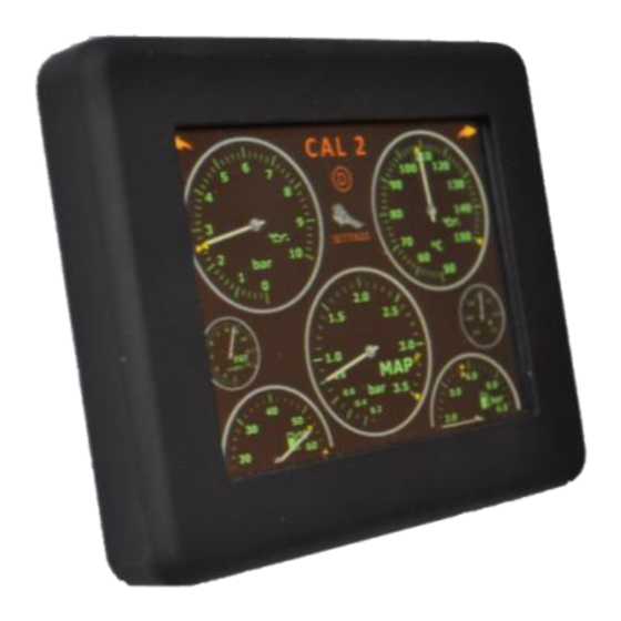
Toucan Touchscreen Gauge and CAL Selection Unit
User Guide (Generic) V1.96A
For Toucan Firmware Version 1.96 and above, all ECUs
Disclaimer
Disclaimer
Although every care is taken with the design of this product, JT Innovations Ltd. can in no
way be held responsible for any consequential damage resulting from the use of Toucan in
your vehicle.
support@JTi.uk.com
Always operate your vehicle safely and do not allow yourself to be distracted by your
Toucan display while driving. Minimise the amount of time you spend viewing the screen.
Do not access any function requiring prolonged use of the menus whilst driving.
www.JTi.uk.com
+44 (0) 1305 534535
support@JTi.uk.com
© JT Innovations Ltd. 2022
Page
1
Advertisement
Table of Contents

Subscribe to Our Youtube Channel
Related Manuals for JT Innovations Toucan

Summary of Contents for JT Innovations Toucan
- Page 1 For Toucan Firmware Version 1.96 and above, all ECUs Disclaimer Disclaimer Although every care is taken with the design of this product, JT Innovations Ltd. can in no way be held responsible for any consequential damage resulting from the use of Toucan in your vehicle.
-
Page 2: Table Of Contents
Extended Gauge Set...... 13 Status Indicators ......13 Introduction Thank you for purchasing a Toucan display. We hope it will be easy to install and configure, and we suggest that you read this guide before installation. Installation Before You Start Please check the box contents to ensure nothing is missing. -
Page 3: Installation
Ensure a good ground connection is provided to the BLACK wire. To allow Toucan to power up quickly, it is recommended that a connection to both a permanent and switched (i.e., only live when the ignition is on) vehicle battery feeds are made. -
Page 4: Cal Switch - Grey Wire
Multiway Connector This connects to the rear of the Toucan unit. Note that it has a latching tab that must be depressed before the connector and cable can be detached. The connector is intended to allow occasional removal of the unit from the car to allow, for example, firmware updates to be applied. -
Page 5: In-Vehicle Mounting
CAL switch configuration If Toucan is being used to select calibrations via the grey wire rather than CANbus (see later), it is necessary to check that the voltage thresholds configured in the ECU match those of your Toucan. Toucan supports 8 or 12 CAL positions. Analogue rotary CAL switches vary, and your mapper may have adjusted the ECU values to match your specific switch. -
Page 6: Doesn't Work
>4.58V 4.80V To ensure Toucan and the ECU calibration match, you can either alter the voltages in the Toucan unit or alter the ECU to match Toucan. Note that switching Toucan between 8 and 12 CAL positions will cause the voltages to default to the values in the tables above. -
Page 7: Datastream Configuration
ECUs via CANbus. G4 and V-series ECUs with a serial number lower than 10,000 will need a CAN upgrade by a Link dealer. Toucan is also capable of activating CAN Digital Input (DI) channels 1 to 8 on Link G4+/G4X and Vi-PEC i-series ECUs... -
Page 8: Can Di Control Functions
20. Click Apply and then OK. 21. Make sure a Store (F4) is performed. There is a “G4” setting available via Toucan’s More Page 4 menu – the available parameters and data scaling is slightly different for the G4. CAN DI Control Functions Link G4+ and Vi-PEC i-series ECUs allow a wide range of parameters to be controlled via a CANbus message that acts as a “CAN Digital Input”. -
Page 9: Syvecs/Life Racing
This is a special mode where the Syvecs ECU replicates the CAN content on an RS232 datastream. This is used if there is a reason Toucan cannot be connected to the ECU CANbus. The exact format of the data is dependent on the CAN RX mode as below. -
Page 10: Toucan Transmit (Tx) Modes
This mode is found in SCAL under “Syvecs CAN Receive” Note that Toucan does not transmit all of the data the comprises the Bosch M4 ABS data set so, unless the vehicle is already transmitting these and the vehicle CAN bus is connected to the Syvecs, there will be errors reported due to the missing frames.This... -
Page 11: 5V Output Modes
5V Output Modes The grey wire in the Toucan cable harness has traditionally been used as a stepped 0-5V control to mimic a rotary CAL switch. Although of limited use for the current range of Syvecs ECUs, if any of the TX modes are being used to control CAL selection instead, this output can be changed to be: •... -
Page 12: Additional Features
CAN bridge module, which then needs CAN data in specific, incompatible slots. On “More Page 4” you can access an editor to alter the Toucan CAN frame and slot assignments. This is considered an Advanced option and should only be done if you are comfortable accessing the calibration in your Syvecs using SCal to determine the frame and slot assignments. -
Page 13: Turning Parameters Off
“Launch Select Switch”, with rpm offsets applied to the base/calibration launch rpm, as set by SCal. Using Toucan’s CAN TX mode, Launch Calibration Switch selection (1 to 12) can be set via the full screen RPM gauge when the CAN TX mode is set to “GEN” (meaning “Generic”, or Syvecs “Generic Receive”... -
Page 14: Emtron
Emtron Toucan can receive runtime parameters and status information from Emtron ECUs and is also capable of sending messages to the ECU to control: • CAL switching • Launch on/off • ALS on/off • Either ALS or Traction Control CAL switching (as preferred) Configuring the Gauge Datastream Files will need to be downloaded from the JTinnovations website –... -
Page 15: Haltech And Ecumaster
Configure the ECU to transmit the “Haltech E8 E11v2” protocol at 1Mbit/s Trim Switch If the ECU variant used supports the use of trim selection switches, Toucan provides an 8-way voltage output to emulate a physical switch. This is named a “CAL” (calibration) output in Toucan. -
Page 16: Motec M1
Select the Physical CANbus channel used (e.g., CAN Bus 1) • Set the CAN ID to 528 (NB – Toucan transmits with ID 529, but the setting in M1 Tune has to be a multiple of 16 as the “base” address for 16 received channels, which in this case is 528). -
Page 17: Alcatek
Please discuss with your mapper. There is no configuration of Toucan necessary. CANbus Termination It will be necessary to enable the bus termination if Toucan is the last device on a CANbus network. By default the termination is switched off, but it may be enabled by sliding the small switch on the rear of the unit towards the 4-prong mounting plate. -
Page 18: Menus And Operation
Menus and Operation Touch here to change current Gauge Screens calibration. Label shown is the Touch here to go to next first 5 characters of the text gauge page entered. Touch here to go to previous gauge page Shows which gauge screen Launch Control status is showing: A, B, C or D. -
Page 19: Settings Menu
Large Gauges Goes to parameter list view. Touch here to return to main gauge screen. Touch here to mute an active alarm. Will automatically unmuted when alarm next clears Resets the peak marker. Settings Menu Touch here to select full Touch here to mute or brightness unmute audible alarms. -
Page 20: Gauge Layout
Gauge Layout This is accessed via the Gauge Setup button, and then “Gauge Select”. Touch the gauge that Touch here to select which of the 4 pages to you wish to change. A 3 letter mnemonic setup describes the current gauge selected for each position Gauge name is shown... -
Page 21: Editing Cal Text
Adjust the voltage up or down. Toucan supports 8 or 12 CAL positions which can be set via the “More” menus. Note that switching Toucan between 8 and 12 CAL positions will cause the voltages to reset to default values. -
Page 22: Cal Pin Protection
CAL PIN Protection. If enabled via the “more” menus, Toucan can be set to prevent the current CAL being changed unless you enter a 4 digit PIN. This can be useful if you have a “valet” CAL (with reduced rpm limit for example) and/or an anti-theft CAL. You can also set PIN protection to only apply to the last CAL (i.e. -
Page 23: Alarm Configuration
Each large gauge has a “mute” button that temporarily mutes the alarm until either it clears and re-occurs; or you unmute it; or Toucan is repowered. In addition, there is a low oil temperature warning that can be enabled. This will not sound the audible alarm but will display a non-flashing orange bezel until the oil temperature exceeds the configured temperature. -
Page 24: Shiftlight Configuration
Shiftlight Configuration If a JT Innovations Shiftlight is connected to Toucan, the shift LEDs can be configured from the Toucan screen. This is accessed via the Shift Light Setup button on the Setup screen. Select to allow modes to be configured for Choose “all LEDs”... -
Page 25: More" Menus
“More” Menus • Turn the audible touchscreen feedback beep on/off The more menus allow you to select • Determine which large gauges • Units used – Metric, Imperial or will be displayed when you cycle “USA” (which uses Imperial through them. This is useful to measurements for everything hide gauges... -
Page 26: Keypad
It will be powered from the PC USB port, although the LCD will be shut down. Note that the “Arkon” AMPS mounting plate on some Toucan units made in 2021 obscures the USB socket. The plate will need to be unscrewed to allow the USB cable to be attached. -
Page 27: Technical
Processing 190MHz 32 bit ARM9, 8Mbytes Flash memory, 8Mbytes SDRAM. system. Package contents Toucan unit, power/data cable harness, mount, installation guide. Available Air charge temperature; Battery Volts; Boost (2.5 bar and 3.5 bar); Gauges/Alarms Exhaust Gas Temperature (2 channels); Fuel level; Fuel Pressure; Fuel (ECU-dependent) Temperature;... -
Page 28: Can Id Ranges And Toucan Auto-Detect
CAN ID Ranges and Toucan Auto-detect Toucan is designed to auto-detect the connected ECU by the CAN stream received, and it does this via the CAN IDs of the received stream. The IDs’ used by each manufacturer are, in the most part, unique (and where not, Toucan has configuration options to take account of the overlaps) but occasionally a conflict might occur, especially if there are other devices on the CANbus.
Need help?
Do you have a question about the Toucan and is the answer not in the manual?
Questions and answers