Table of Contents
Advertisement
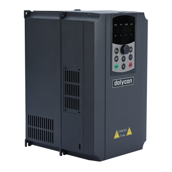
CT100G Series Inverter
Safety precautions
Keep the signal cables of the inverter away from the power cables as far as
»
possible, or distribute the two categories of cables vertically-crossed if the
distance is not far enough, otherwise it may cause signal interference.
» Ensure that all the screws are tightened when wiring, otherwise damage to
the inverter may occur.
» The encoders and sensors should be applied with the shielded cables and
the shielded layer should be grounded reliably.
Operation
» Confirm that the wiring is completed and correct and then cover the plate
before power on.
» Do not open the plate after power on, otherwise electric shock may occur.
» Operate the inverter appropriately, otherwise damage to the inverter may
occur.
» Non-professionals are not allowed to test the signals when the inverter is
running. Otherwise, physical injury or damage to the devices may occur.
» Do not change the parameters of the inverter at random, otherwise damage
to the inverter may occur.
» Do not touch the fans and brake resistors, otherwise it may cause
mechanical injury or burn.
» Do not start up or stop the inverter by power on or off, otherwise damage to
the inverter may occur.
» Ensure that the circuit breakers or contactors at the output sides of the
inverter are not in output state before switching, otherwise damage to the
inverter may occur.
- 3 -
Advertisement
Table of Contents

Related Manuals for dolycon CT100G Series


Summary of Contents for dolycon CT100G Series
- Page 1 CT100G Series Inverter Safety precautions Keep the signal cables of the inverter away from the power cables as far as » possible, or distribute the two categories of cables vertically-crossed if the distance is not far enough, otherwise it may cause signal interference.
- Page 2 CT100G Series Inverter Safety precautions Others » This inverter is not suitable for the occasions when the specifications exceed those specified in this manual. If you have special requirements, please contact our technical department. » The inverter is equipped with surge suppressors inside, which can protect it from the lightning.
-
Page 3: Chapter 1 Product Information
CT100G Series Inverter CHAPTER 1 PRODUCT INFORMATION CHAPTER 1 PRODUCT INFORMATION 1.1 Product model name rules The letters and numbers of the type designation key indicate product series, voltage, power, load etc. Figure 1-1 Type designation key 1.2 Product specifications and technical parameters 1.2.1 Product specifications... - Page 4 CT100G Series Inverter CHAPTER 1 PRODUCT INFORMATION CT100G-4T-5.5G-B 18.5 CT100G-4T-7.5G-B 22.5 18.5 CT100G-4T-11G-B 30.0 25.0 CT100G-4T-15G-B 39.0 32.0 CT100G-4T-18.5G-B 18.5 45.0 38.0 18.5 CT100G-4T-22G-B 54.0 45.0 CT100G-4T-30G-B 68.0 60.0 CT100G-4T-37G 84.0 75.0 CT100G-4T-45G 98.0 92.0 CT100G-4T-55G 123.0 115.0 CT100G-4T-75G 157.0 150.0...
- Page 5 CT100G Series Inverter CHAPTER 1 PRODUCT INFORMATION Single-phase 220VAC±15% Input voltage Three-phase 380VAC±15% Input frequency 50~60Hz±5% Input and output Output voltage 0~Rated input voltage parameters Output frequency 0~500Hz, unit 0.01Hz Overload 150% of rated current: 60s; 180% of rated capacity current: 10s;...
- Page 6 CT100G Series Inverter CHAPTER 1 PRODUCT INFORMATION Standard 2-channel multi-function collector Digital output outputs, one of which can be high-speed pulse output (HDO). Relay output Standard 2-channel relay outputs RS485 communication interface for external Communication RS485 communication, support Modbus protocol...
- Page 7 CT100G Series Inverter CHAPTER 1 PRODUCT INFORMATION a) C0 models b) C1,C2 models c) C3~C6 models - 9 -...
- Page 8 CT100G Series Inverter CHAPTER 1 PRODUCT INFORMATION d) C7,C8 models e) C11,C12 models Figure 1-2 Product appearance and installation dimensions diagram Table 1-3 Structure, mounting dimension and weight - 10 -...
- Page 9 CT100G Series Inverter CHAPTER 1 PRODUCT INFORMATION Appearance and dimensions(mm) Installing Inverter mode weight cabinet hole(mm) CT100G-2S-0.7G-B CT100G-2S-1.5G-B CT100G-2S-2.2G-B CT100G-4T-0.7G-B 155 115 175 CT100G-4T-1.5G-B CT100G-4T-2.2G-B CT100G-4T-4.0G-B CT100G-4T-5.5G-B CT100G-4T-7.5G-B 172 128 218 CT100G-4T-11G-B 200 153 273 CT100G-4T-15G-B CT100G-4T-18.5G-B CT100G-4T-22G-B 205 184 360 385 11.5...
- Page 10 CT100G Series Inverter CHAPTER 1 PRODUCT INFORMATION 1.4 Outline and size of keypad Figure 1-3 Structure diagram of the keypad (unit: mm) Figure 1-4 Structure diagram of the outer bracket (unit: mm) Note: while use external keypad, the wire should not be more than 30m, otherwise there is risk of keypad not work.
-
Page 11: Chapter 2 Installation And Wiring
CT100G Series Inverter CHAPTER 2 INSTALLATION AND WIRING CHAPTER 2 INSTALLATION AND WIRING 2.1 Installation environment 1. Ambient temperature: -10℃~+40℃, derate to use if the temperature is above 40℃ 2. Relative humidity: ≤ 95%, no condensation 3. Vibration: <0.5g 4. The inverter should be installed on the flame-retardant materials and there is enough space for heat dissipation. - Page 12 CT100G Series Inverter CHAPTER 2 INSTALLATION AND WIRING and braking during braking. resistor Reduce the protection of the inverter due to leakage current; Output reactor When the cable connecting the inverter and the motor is more than 100m, it is recommended to install the output reactor.
- Page 13 CT100G Series Inverter CHAPTER 2 INSTALLATION AND WIRING 2.2.3 Specifications of cables, circuit breakers and contactors Table 2-2 Specifications of the cables, the circuit breakers and the contactors Braking Circuit contacto units&resistors Cables breaker Inverter mode r(A) Power (A) Resist (Ω)...
-
Page 14: Standard Wiring Diagram
CT100G Series Inverter CHAPTER 2 INSTALLATION AND WIRING Braking Circuit contacto units&resistors Cables breaker Inverter mode r(A) Power (A) Resist (Ω) (KW) 240*4 2400 1800 CT100G-4T-630G Note: When the inverter is built-in with braking units, the power and resistance of the braking resistors should be as required above the table, otherwise the damage to the inverter may occur. - Page 15 CT100G Series Inverter CHAPTER 2 INSTALLATION AND WIRING Figure 2-2 Standard wiring diagram 2.4 Control circuit connection 2.4.1Precautions Please apply the multi-core shielded cable or twisted pair to connect the control terminals. When using the shielded cable (near one side of the inverter), connect it to the PE terminal of the inverter.
- Page 16 CT100G Series Inverter CHAPTER 2 INSTALLATION AND WIRING Figure 2-3 Schematic diagram of the control plate 2.4.3 Pins of the control plate Table 2-4 Pin instructions of the control plate Instructions RS485 terminating resistor setting - 18 -...
- Page 17 CT100G Series Inverter CHAPTER 2 INSTALLATION AND WIRING Short circuit the pins 1 and 2 of X1 by short-circuit module, the terminating resistor of 120Ωis used for RS485 bus; Short circuit the pins 2 and 3 of X1 by short-circuit module, the terminating resistor is not used for RS485 bus;...
- Page 18 CT100G Series Inverter CHAPTER 2 INSTALLATION AND WIRING Figure 2-5 control board terminal ports Figure 2-6 control board terminal label nctions of the main circuit terminals 2.4.5 Fu Table 2-5 Functions of the control board terminals Categor Terminal Terminal function...
- Page 19 CT100G Series Inverter CHAPTER 2 INSTALLATION AND WIRING input +10V or 5V power available via X13, optional output Output current range: 0~50mA (If the potentiometer is connected between +10V/+5V and GND, the resistance should not be less than 2kΩ.) Input voltage and current are...
- Page 20 CT100G Series Inverter CHAPTER 2 INSTALLATION AND WIRING Figure 2-7 Wiring of NPN type sink current By using the internal +24V power supply of the inverter, the wiring of the external controller for the PN type source current is as shown below:...
- Page 21 CT100G Series Inverter CHAPTER 2 INSTALLATION AND WIRING By using the external power supply, the wiring of the external controller for the PNP type source current is as shown below: Figure 2-10 Wiring of PNP type source current Note: Be sure to remove the short-circuit plate between +24V and PW.
-
Page 22: Chapter 3 Operation And Power On Explain
CT100G Series Inverter CHAPTER 3 OPERATION AND POWER ON EXPLAIN CHAPTER 3 OPERATION AND POWER ON EXPLAIN 3.1Keypad explain The keypad consists of three parts for unit/status LEDs displaying, parameters displaying and key operation, as shown below. Figure 3-1 Keypad 3.1.1 Unit and status LED... - Page 23 CT100G Series Inverter CHAPTER 3 OPERATION AND POWER ON EXPLAIN On: communication run command reference mode Off: no fault alarm Blinking: fault alarm or automatic study Alarm LED parameter On: torque control 3.1.2 Code displaying zone 5-figure LED display can display the monitoring data such as the set frequency and the output frequency and alarm codes.
-
Page 24: Fault Reset
CT100G Series Inverter CHAPTER 3 OPERATION AND POWER ON EXPLAIN for stop protection of the inverter[3]; At fault or stop state, the key is used as a reset key to clear the fault alarm information. Increase function group in the 1st/2nd level menu progressively;... -
Page 25: Password Setting
CT100G Series Inverter CHAPTER 3 OPERATION AND POWER ON EXPLAIN To obtain good control performance, the motor must be self-identification of the parameters to obtain the exact parameters of the controlled motor; you must input correct motor parameters according to the name plate before identification, CT series inverters will match the parameters with the standard motor parameters. -
Page 26: Fault State
》 key to switch to the right to display the selected parameters, press the MF key to switch the left to display the selected parameters. CT100G series inverters provide a variety of fault information. Please refer to chapter 6 fault reason and solution. - Page 27 CT100G Series Inverter CHAPTER 3 OPERATION AND POWER ON EXPLAIN Figure 3-3 First power flow chart - 29 -...
-
Page 28: Chapter 4 Function Parameter Table
CHAPTER 4 FUNCTION PARAMETER TABLE CHAPTER 4 FUNCTION PARAMETER TABLE CT100G series inverters have 16 groups of function codes F00~F15 and factory group F16. The function codes have been divided into three levels. For example, “F08.08” means the eighth function code in the P8 function group. F15 group is factory group, and users are forbidden to access these parameters. - Page 29 CT100G Series Inverter CHAPTER 4 FUNCTION PARAMETER TABLE Functio Default Attrib Name Detailed instruction of parameters n code value ution 0:speed sensorless vector control Motor control mode 1:reserved F00.00 ☆ 2:V/F control 0: keypad run command channel (LED off) 1: terminal running command channel F00.01 Run command channel...
- Page 30 CT100G Series Inverter CHAPTER 4 FUNCTION PARAMETER TABLE Functio Default Attrib Name Detailed instruction of parameters n code value ution 1:motor 2 0.00s~650.00s (F00.16=2) F00.14 ACC time 1 0.0s~6500.0s (F00.16=1) 20.0 ○ 0s~65000s (F00.16=0) 0.00s~650.00s (F00.16=2) F00.15 DEC time 1 0.0s~6500.0s (F00.16=1)
- Page 31 CT100G Series Inverter CHAPTER 4 FUNCTION PARAMETER TABLE Functio Default Attrib Name Detailed instruction of parameters n code value ution 1: change frequency asynchronous motor Rated power of asynchronous Depend on model F01.02 ☆ motor Rated frequency of F01.03 0.01Hz~ (Max. frequency)F00.06 50.00...
- Page 32 CT100G Series Inverter CHAPTER 4 FUNCTION PARAMETER TABLE Functio Default Attrib Name Detailed instruction of parameters n code value ution F02 Group Start and stop control 0: start at the starting frequency F02.00 Start mode 1: start after rotating speed tracking ○...
- Page 33 CT100G Series Inverter CHAPTER 4 FUNCTION PARAMETER TABLE Functio Default Attrib Name Detailed instruction of parameters n code value ution F03 Group V/F control 0: straight line V/F curve 1: multi-dots V/F curve 2: square V/F curve 3: 1.2 V/F curve F03.00...
- Page 34 CT100G Series Inverter CHAPTER 4 FUNCTION PARAMETER TABLE Functio Default Attrib Name Detailed instruction of parameters n code value ution 220V:380V 380V:760V 0:invalid Overvoltage stall enable F03.20 ○ 1:valid Current compensation F03.21 coefficient of double speed 50~200% ☆ over-current stall action 200.0v~2000.0v set according to model...
- Page 35 CT100G Series Inverter CHAPTER 4 FUNCTION PARAMETER TABLE Functio Default Attrib Name Detailed instruction of parameters n code value ution 0:F04.09 set 1:AI1 2:AI2 reserve Speed control (drive) torque F04.10 4:HDI high speed pulse setting ○ max limit source 5:communication setting 6:min (AI1,AI2)
- Page 36 CT100G Series Inverter CHAPTER 4 FUNCTION PARAMETER TABLE Functio Default Attrib Name Detailed instruction of parameters n code value ution 501: recover user parameters F05.02 reserved 0~65535 ● F05.03 User password 0~65535 ○ 0: MF invalid 1:switch between keypad command and remote command F05.04...
- Page 37 CT100G Series Inverter CHAPTER 4 FUNCTION PARAMETER TABLE Functio Default Attrib Name Detailed instruction of parameters n code value ution Bit02:DI input state Bit03:DO output state Bit04: AI1 voltage (v) Bit05: AI2 voltage (v) reserve Bit06: BIT07: Count value BIT08: Length value...
- Page 38 CT100G Series Inverter CHAPTER 4 FUNCTION PARAMETER TABLE Functio Default Attrib Name Detailed instruction of parameters n code value ution 25: counter input 26: counter reset 27: length count input 28: length reset 29: torque control forbid 30: high speed pulse (pulse) frequency...
- Page 39 CT100G Series Inverter CHAPTER 4 FUNCTION PARAMETER TABLE Functio Default Attrib Name Detailed instruction of parameters n code value ution F06.18 Curve 2 minimum input 0.00V~F06.20 0.00 ○ Curve2 minimum input F06.19 -100.0%~100.0% ○ corresponding setting F06.20 Curve 2 maximum input F06.18~10.00V...
- Page 40 CT100G Series Inverter CHAPTER 4 FUNCTION PARAMETER TABLE Functio Default Attrib Name Detailed instruction of parameters n code value ution reserve Ten thousand place: F07 Group Output terminals 0:pulse output F07.00 HDO output mode ○ 1:switch output F07.01 HDO switch output selection 0: no output ○...
- Page 41 CT100G Series Inverter CHAPTER 4 FUNCTION PARAMETER TABLE Functio Default Attrib Name Detailed instruction of parameters n code value ution 1: set frequency F07.07 AO1 ○ output selection 2: output current 3:output torque 4:output power 5:output voltage 6:high speed pulse output(100.0% corresponding to 100.0kHz)...
- Page 42 CT100G Series Inverter CHAPTER 4 FUNCTION PARAMETER TABLE Functio Default Attrib Name Detailed instruction of parameters n code value ution 0: no detection 1: overload warning is valid in running, continue to run 2: overload warning is valid in running,...
- Page 43 CT100G Series Inverter CHAPTER 4 FUNCTION PARAMETER TABLE Functio Default Attrib Name Detailed instruction of parameters n code value ution 16: inverter radiator overheating (E.oH2) 17: external fault (E.EF) 18: communication failure (E.485) 19: current detection fault(E.ItE) 20: motor parameter learning fault (E.AUt)...
- Page 44 CT100G Series Inverter CHAPTER 4 FUNCTION PARAMETER TABLE Functio Default Attrib Name Detailed instruction of parameters n code value ution F08.27 Frequency at second fault 0.00 ● F08.28 Current at second fault 0.00 ● Bus voltage at second fault F08.29 ●...
- Page 45 CT100G Series Inverter CHAPTER 4 FUNCTION PARAMETER TABLE Functio Default Attrib Name Detailed instruction of parameters n code value ution 2:continue running Ten place: user define fault 2(E.uD2) 0:free stop 1:stop as stop mode 2:continue running ten place:power on time arrive(E.PTo)...
- Page 46 CT100G Series Inverter CHAPTER 4 FUNCTION PARAMETER TABLE Functio Default Attrib Name Detailed instruction of parameters n code value ution F08.64 Over speed detection value 0.0%~50.0% (max frequency) 20.0 ○ 0.0s:no detection F08.65 Over speed detection time ○ 0.1~60.0s Detection value for too big F08.66...
- Page 47 CT100G Series Inverter CHAPTER 4 FUNCTION PARAMETER TABLE Functio Default Attrib Name Detailed instruction of parameters n code value ution F09.22 PIDparameter change bias 2 F10.21~100.0% 80.0 ○ PID initial value 0.0%~100.0% F09.23 ○ F09.24 PID initial value keep time 0.00~650.00...
- Page 48 CT100G Series Inverter CHAPTER 4 FUNCTION PARAMETER TABLE Functio Default Attrib Name Detailed instruction of parameters n code value ution (100.0% of max frequency F00.06) -100.0%~100.0% F11.10 Multi-step speed command 10 ○ (100.0% of max frequency F00.06) -100.0%~100.0% F11.11 Multi-step speed command 11 ○...
- Page 49 CT100G Series Inverter CHAPTER 4 FUNCTION PARAMETER TABLE Functio Default Attrib Name Detailed instruction of parameters n code value ution F11.36 Step 9 running time 0.0s (h)~6553.5s (h) ○ PLC step 9 ACC/DEC time F11.37 0~3 ○ selection F11.38 Step 10 running time 0.0s (h)~6553.5s (h)
- Page 50 CT100G Series Inverter CHAPTER 4 FUNCTION PARAMETER TABLE Functio Default Attrib Name Detailed instruction of parameters n code value ution F12.03 Response delay 0ms~20ms ○ Communication timeout F12.04 0.0(invalid),0.1s~60.0s ○ detection time Unit position: not standard MODBUS-RTU protocol Data transfer format selection 0:not standard MODBUS-RTU protocol F12.05...
- Page 51 CT100G Series Inverter CHAPTER 4 FUNCTION PARAMETER TABLE Functio Default Attrib Name Detailed instruction of parameters n code value ution Frequency detection value F13.26 0.00Hz~Max. Frequency F00.06 50.00 ○ (FDT2) Frequency detection delay F13.27 0.0%~100.0%(FDT2 level) ○ value (FDT2) Any arrival detection frequency F13.28...
- Page 52 CT100G Series Inverter CHAPTER 4 FUNCTION PARAMETER TABLE Functio Default Attrib Name Detailed instruction of parameters n code value ution Ten place: A00-A15 parameter group display selection 0: not display 1: display Unit place: user determine parameter group display selection...
- Page 53 CT100G Series Inverter CHAPTER 4 FUNCTION PARAMETER TABLE Functio Default Attrib Name Detailed instruction of parameters n code value ution Vitual VDI4 terminal function A01.03 0~59 ☆ selection Vitual VDI5 terminal function A01.04 0~59 ☆ selection 0:inner connect vitual Dox...
- Page 54 CT100G Series Inverter CHAPTER 4 FUNCTION PARAMETER TABLE Functio Default Attrib Name Detailed instruction of parameters n code value ution 0-positive logic; 1-nagetive logic Unit place:VDO1 VDO output terminal valid Ten place:VDO2 A01.21 11111 ☆ state selection Hundred place:VDO3 Thousand place:VDO4...
- Page 55 CT100G Series Inverter CHAPTER 4 FUNCTION PARAMETER TABLE Functio Default Attrib Name Detailed instruction of parameters n code value ution 4: Line-saving UVW encoder 0:local PG A02.14 Speed feedback PG selection 1:expand PG ☆ 2:HDI high speed pulse input (DI5)
- Page 56 CT100G Series Inverter CHAPTER 4 FUNCTION PARAMETER TABLE Functio Default Attrib Name Detailed instruction of parameters n code value ution A02.36 Integral gain of M axis 0~60000 1300 ○ Proportional gain of T axis 0~60000 A02.37 2000 ○ A02.38 Integral gain of T axis 0~60000...
- Page 57 CT100G Series Inverter CHAPTER 4 FUNCTION PARAMETER TABLE Functio Default Attrib Name Detailed instruction of parameters n code value ution 690v:650v 1140v:1100v A05.07 reserved reserved ☆ A05.08 Dead zone time adjust 100%~200% ☆ 200.0v~2200.0vset by models A05.09 Over voltage point setting 810.0...
- Page 58 CT100G Series Inverter CHAPTER 4 FUNCTION PARAMETER TABLE Functio Default Attrib Name Detailed instruction of parameters n code value ution 1: slave machine follow main machine run command to run Ten place: slave machine fault information transmit 0: slave machine fault information not...
- Page 59 CT100G Series Inverter CHAPTER 4 FUNCTION PARAMETER TABLE Functio Default Attrib Name Detailed instruction of parameters n code value ution A09.09 Wake up delay time 0.0s~2500.0s ○ A09.10 Reserved 0:frequency Dormancy valid ; A09.11 Dormancy selection ○ 1: pressure Dormancy valid ;...
- Page 60 CT100G Series Inverter CHAPTER 4 FUNCTION PARAMETER TABLE Functio Default Attrib Name Detailed instruction of parameters n code value ution b00.34 Reserved ● b00.35 Aim torque unit:% ● Reserved b00.36 ● b00.37 Power factor angle unit:° ● b00.38 Reserved ●...
-
Page 61: Chapter 5 Communication Protocol
CHAPTER 5 COMMUNICATION PROTOCOL CHAPTER 5 COMMUNICATION PROTOCOL The CT100G series inverters provide RS485 communication interface. You can realize centralized control via PC/PLC (set the run commands and function parameters of the inverter, read the work state and fault information of the inverter) to meet the specific requirements. - Page 62 5. Communication data format The Modbus protocol communication data format of CT100G series inverters is as follows: In RTU mode, the minimum interval time should be at least 3.5 bytes for message transmission, which is the easiest way to achieve a variety of character time at the baud rate.
Need help?
Do you have a question about the CT100G Series and is the answer not in the manual?
Questions and answers