Table of Contents
Advertisement
Operating Manual
R-Series Measuring Devices
(Models RA | RCA | RCS | RCFF)
Version 2.2 | 15.09.2020
© 2012 by Vogel & Plötscher GmbH & Co. KG
Vogel & Plötscher GmbH & Co. KG
Geldermannstrasse 4
D-79206 Breisach
Tel: +49 (0)7667 946100 - Fax: +49 (0)7667 946120 - E-mail: info@voploe.de - Web: www.vogelundploetscher.de
Advertisement
Table of Contents

Related Manuals for Vogel & Plötscher R Series


Summary of Contents for Vogel & Plötscher R Series
- Page 1 Operating Manual R-Series Measuring Devices (Models RA | RCA | RCS | RCFF) Version 2.2 | 15.09.2020 © 2012 by Vogel & Plötscher GmbH & Co. KG Vogel & Plötscher GmbH & Co. KG Geldermannstrasse 4 D-79206 Breisach Tel: +49 (0)7667 946100 - Fax: +49 (0)7667 946120 - E-mail: info@voploe.de - Web: www.vogelundploetscher.de...
-
Page 2: Table Of Contents
Table of contents 1. General 2. Commissioning 2.1 Device description 2.2 Preparation 2.3 Calibrating the spirit level 3. Operation | Measurement 3.1 Measuring track gauge 3.2 Measuring flangeway clearance 3.3 Measuring check rail gauge 3.4 Measuring back-to-back distance 3.5 Measuring cant 4. -
Page 3: General
1. General The measuring devices of the R-series (= models RA | RCA | RCS | RCFF) are analogue instruments for the checking of vignole and grooved rails on railway and tram systems. The measuring devices are modular in design, and can be custom-configured. In order to ensure correct application, please be sure to comply with the nominal track gauges specified in chapter 6 (Technical data) as well as the permissible measuring ranges. -
Page 4: Commissioning
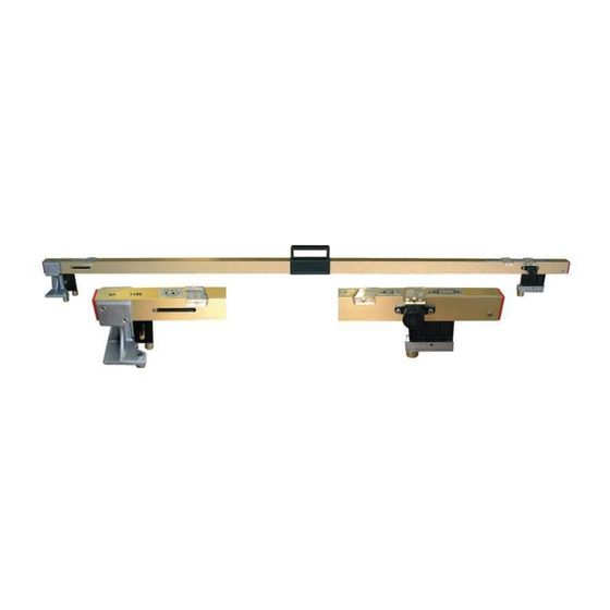
2. Commissioning 2.1 Device description The measuring device consists of a solid anodised aluminium tube. In the separable variant (→ Options) the measuring device can be separated asymmetrically. Figure 1: Device description for model RCA Item 1: Broad contact Item 2: Shifter for flangeway measurement (RA | RCA) Item 3: Readout window for flangeway measurement (RA | RCA) -
Page 5: Preparation
2.2 Preparations The measuring devices of the R-series are state-of-the-art units, guaranteeing a high degree of reliability. However, that reliability can only be attained in practice if all the necessary measures are taken. It falls within the duty of care of the company operating the measuring device to ensure that those measures are taken, and to monitor their implementation. -
Page 6: Calibrating The Spirit Level
Calibrating the spirit level The spirit level must be checked and adjusted as necessary prior to use. Preliminary remarks The permissible tolerance for cant measurements is ± 1 mm. The cant measurement fine adjuster mechanism is optimised for clockwise operation. Procedure On a section of track with a maximum cant of 20 mm, position the measuring device and measure the cant (= 1... -
Page 7: Operation | Measurement
3. Operation | Measurement When measuring, both measuring bolts of the broad contact must be contacting on the rail head in order to avoid measurement inaccuracies resulting from angle errors. 3.1 Measuring track gauge (RA | RCA | RCS | RCFF) Position the measuring device on the track at the measuring point. -
Page 8: Measuring Flangeway Clearance
3.2 Measuring flangeway clearance (RA | RCA) Position the measuring device on the track at the measuring point. Push the sliding bolt towards the track construction (e.g. check rail or wing rail) until the measuring bolt makes contact. Read off the measured value. -
Page 9: Measuring Back-To-Back Distance
3.4 Measuring back-to-back distance (RA | RCA) Position the measuring device on the track at the measuring point. Fix it in place such that the measuring bolt of the flangeway slider makes contact on the inside (i.e. on the check rail)! With the fine adjuster, turn the measuring bolt of the narrow contact towards the wing rail as far as it will go and read off the measured value. - Page 10 3.5 Cant (RCA | RCS | RCFF) Position the measuring device on the track at the measuring point. Turn the air bubble in the spirit level to the zero setting using the cant pivot handle. Read off the measured value. Figure 6: Measuring cant Optimum cant measurement accuracy is assured when the measured value is approached on the readout scale from left to right (= i.e.
-
Page 11: Options
4. Options 4.1 Option -T (separation) Separable measuring device variant (asymmetric). Figure 7: Option -T (example: RCA-T) Figure 8: Separating (turn anti-clockwise) Figure 9: Lateral adjustment of both section Figure 10: Joining of the separation in reverse order Operating Manual R-Series | Version 2.2 | 15.09.2020 ©... -
Page 12: Option -P
4.2 Option -P (blade inspection adapter) Detach the blade inspection adapter from the retaining bolt and slot it onto the measuring bolt. For the test conditions refer to the relevant inspection standards. Figure 11 Figure 12 4.3 Option -H (crossing tip inclination) Position the measuring device on the crossing. -
Page 13: Option -R20
4.5 Option -R20 (flangeway 20 mm) This option enables the measurement of grooved rails with flangeway clearances of ≥ 20 mm. 4.6 Option -W (changeable probes) Changeable bolts can be used to adapt the measuring device variably to country-specific standards and/or different rail types (e.g. -
Page 14: Ec Declaration Of Conformity
5. EC Declaration of Conformity as per Annex II A of the Machinery Directive (98/37/EC) The manufacturer: Vogel & Plötscher GmbH + Co. KG Geldermannstrasse 4 79206 Breisach hereby declares that the measuring devices described here of the type RA | RCA | RCS | RCFF comply with the following applicable requirements: 98/37/EC, Annex I... -
Page 15: Technical Data
6. Technical data Nominal track gauge 1435 mm Measuring ranges RCFF Track gauge 1415 – 1475 mm 1415 – 1475 mm 1415 – 1500 mm 1415 – 1500 mm Flangeway clearance 30 – 83 (125) mm 30 – 83 (125) mm (TSI) Check rail gauge 1385 –... - Page 16 Nominal track gauge 1000 mm Measuring ranges RCFF Track gauge 980 – 1040 mm 980 – 1040 mm 985 – 1065 mm 985 – 1065 mm Flangeway clearance 30 – 83 mm 30 – 83 mm Check rail gauge 950 – 970 mm 950 –...
- Page 17 Nominal track gauge 1067 mm Measuring ranges RCFF Track gauge 1047 – 1107 mm 1047 – 1107 mm 1052 – 1132 mm 1052 – 1132 mm Flangeway clearance 30 – 83 mm 30 – 83 mm Check rail gauge 1017 – 1037 mm 1017 - 1037 mm Back-to-back distance 977 –...
- Page 18 Nominal track gauge 1524 mm Measuring ranges RCFF Track gauge 1504 - 1564 mm 1509 - 1572 mm 1509 – 1589 mm 1509 – 1589 mm Flangeway clearance 30 – 83 (125) mm 30 – 83 (125) mm (TSI) Check rail gauge 1474 –...
- Page 19 Nominal track gauge 1668 mm Measuring ranges RCFF Track gauge 1648 – 1708 mm 1648 – 1708 mm 1653 – 1733 mm 1653 – 1733 mm Flangeway clearance 30 – 83 (125) mm 30 – 83 (125) mm (TSI) Check rail gauge 1618 –...
- Page 20 Nominal track gauge 1676 mm Measuring ranges RCFF Track gauge 1656 – 1716 mm 1656 – 1716 mm 1661 – 1741 mm 1661 – 1741 mm Flangeway clearance 30 – 83 (125) mm 30 – 83 (125) mm (TSI) Check rail gauge 1626 –...
-
Page 21: Care And Maintenance
7. Care and maintenance 7.1 Care After every use the measuring device must be cleaned, dried and stored in a dry room. 7.2 Maintenance The measuring device must be inspected and calibrated at regular intervals (usually every 12 months) at the manufacturer's facility or by a qualified and authorised body. 7.3 Contact details If you have any questions or problems relating to the measuring device, please contact your local Vogel &...
Need help?
Do you have a question about the R Series and is the answer not in the manual?
Questions and answers