
Related Manuals for Fotona QX MAX

Summary of Contents for Fotona QX MAX
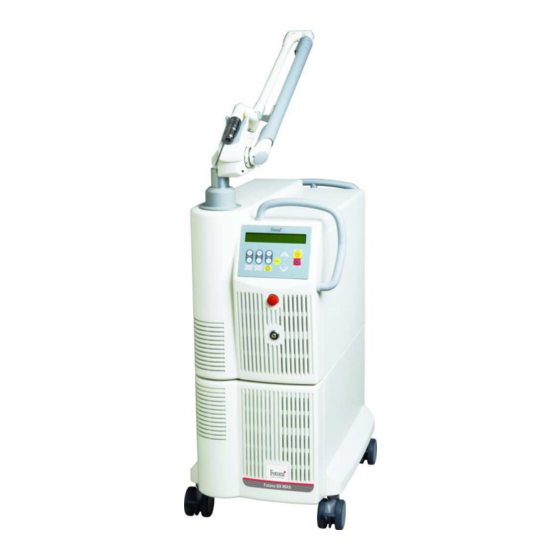
- Page 1 MANUFACTURER: Fotona d.d. Stegne 7 SI – 1000 Ljubljana, Slovenia phone: + 386 1 500 91 00 fax: + 386 1 500 92 00 www.fotona.com SERVICE MANUAL Fotona QX MAX Model: M031-3A/2 83826 SM ENG/05...
- Page 2 Page 2/94 83826 SM ENG/5...
- Page 3 Copyright © 2008 Fotona d.d. Printed in Slovenia. All rights reserved. The contents of this publication may not be reproduced in any form without the explicit permission of Fotona d.d. 83826 SM ENG/5...
-
Page 4: Table Of Contents
Content 1.SPECIFICATIONS............................9 1.1.Laser................................9 1.2.General................................10 2.FUNCTIONAL DIAGRAM DESCRIPTION.....................12 2.1.Mains inlet and auxiliary power supplies.....................12 2.2.Power distribution circuit – Relay soft start board..................13 2.3.Controller..............................13 2.4.Control panel with display assembly......................14 2.5.Charger assembly............................14 2.6.PFM MODULE assembly..........................15 2.7.Cooling System assembly...........................15 2.8.Laser head assembly..........................16 2.8.1.Nd:YAG Laser module..........................16 2.8.1.1.Polarizer............................16 2.8.1.2.Electro optical... - Page 5 4.2.Use of external notebook computer for advanced service................34 4.2.1.Setup of external notebook computer....................34 4.2.2.Connection of external notebook computer to the Controller...............34 4.2.3.Service mode with external notebook computer...................35 4.2.4.Fotona QX MAX system firmware parameters ..................37 4.2.4.1.For Nd:YAG laser:..........................37 4.2.4.2.For KTP operation..........................37 4.3.Using EPEM communication software......................38 4.3.1.Connection...
- Page 6 6.5.1.Nd:YAG energy meters calibration.......................66 6.5.1.1.Checking the Q-SW energy meter calibration................66 7.Nd Q-SW Energy meter calibration 1 (field service, preferred)..............66 7.1.Nd Q-SW Energy meter calibration 2....................67 7.1.1.ACC energy meter calibration.......................67 7.1.1.1.ACC energy meter calibration test....................67 7.1.1.2.ACC energy meter calibration......................67 7.1.2.KTP energy meters calibration......................68 7.1.2.1.Checking the KTP energy meter calibration..................68...
- Page 7 ......................85 8.3.5.The system does not respond to the footswitch...................85 8.3.6.Calibration time too long ........................85 8.3.7.The expected treatment effect is weaker then usual................85 9.SCHEMATICS..............................86 9.1.Fotona QX MAX electrical wiring diagram....................86 9.2.Flash lamp replacement..........................86 9.3.Simmer trigger board layout........................86 9.4.Head Control layout.............................86 9.5.Energy meter layout ............................86...
- Page 8 SHOCK! NOTE THE ADJUSTMENT, ALIGNMENT AND CALIBRATION SERVICING PROCEDURES CAN BE PERFORMED BY QUALIFIED SERVICING PERSONS AUTHORIZED BY FOTONA D.D. ONLY. CONTACT YOUR RETAILER FOR FOTONA AUTHORIZED SERVICE PERSONNEL. CAUTION DURING THE ADJUSTMENT, ALIGNMENT AND CALIBRATION PROCEDURES THE SERVICEMAN AND ALL PERSONNEL PRESENT IN THE LASER ROOM MUST USE APPROPRIATE SAFETY GOGGLES.
-
Page 9: Specifications
1. Specifications 1.1. Laser Q-switched Long Pulse Accelera Nd:YAG Nd:YAG Laser wavelength: 1064 nm Output energy per pulse: Up to 1600 mJ Up to 5 J Max. fluence 12.7 J/cm 160 J/cm Pulse repetition rate (frequency): 0.5 to 10 Hz 0.5 to 2.2 Hz Pulse width: 5 –... -
Page 10: General
Power requirements 1.2. General Rated voltage: 230 V Long term input power: 2.3 kVA Long term current rating: 10 A Momentary input power: 3.9 kVA Momentary current rating: 17 A Frequency: 50/60 Hz Electrical connection: Non-detachable power supply cord Class of equipment: Class 1 equipment Type of equipment: Type B equipment... - Page 11 Status keys: STANDBY - to enter the standby state READY - to enter the ready state Safety goggles: To operate the device in accordance with IEC 60825-1/2007 safety goggles with the following safety levels are prescribed (in accordance with EN 207:1998/A1:2003): - for 1064 I,R 1064 LB6 (OD 6) and/or 532 I,R 532 LB6 or OD 6 (elsewhere) - for 585nm: I R 585 LB5 (for Europe) or...
-
Page 12: Functional Diagram Description
2. Functional diagram description Please refer to attached drawing Fotona QX MAX Model M031-3A or M001-13A functional diagram. The wiring diagram is also applicable. The M031-3A, M001-13A console consist from the following sub-units: • Mains inlet and auxiliary power supplies comprising of: •... -
Page 13: Power Distribution Circuit - Relay Soft Start Board
CRC check. After the completing of this check it performs the checking of the Emergency Stop switch status and the Key Switch status. If both are not activated it shows on the control panel display of Fotona QX MAX the Fotona logo and waits for the Key Switch to be activated. -
Page 14: Control Panel With Display Assembly
NOTE: The Fotona QX MAX charger is dual simmer current capable of charging the capacitor bank to 800VDC. At the time of the Fotona QX MAX system design it was not used in any other Fotona laser system. Page 14/94... -
Page 15: Pfm Module Assembly
NOTE: The standard PFM assembly features the “crowbar” function. Because of operational principles of the Fotona QX MAX laser this function must be disabled. Placing the jumper JP1 on the PFM control PCB to pins 2,3 disables “crowbar” function. •... -
Page 16: Laser Head Assembly
Q-switch function is to change the optical energy losses inside the laser between the laser mirrors. In case of Fotona QX MAX the Q-switch reduces the losses – enable the laser action. It is done by rotating the EM field beam polarization to the angle that is necessary to pass through the analyzer. -
Page 17: Simmer Trigger Board
Elaser = A + B * Ubank NOTE: The A and B parameters can be accessed and edited in the service mode of operation of the Fotona QX MAX Laser system. Corresponding external computer directory (set ktp) separates the Nd:YAG and KTP parameters A and B. -
Page 18: Beam Sampling Optics
The functions of the energy meters are: • Receives from the system controller the starting (initiating) sequence. • Sends (returns) the acknowledge status and measures the energy. • To amplify the signals from each photo-diode detector, time integrate it and hold it for processing. During factory calibration of the energy meters or during service calibration the gain of this amplifiers can be trimmed to calibrate the energy meter sensitivity. -
Page 19: Oven Control Pcb
• To receive commands from the Controller for opening or closing the shutter via optical link OW3 • To sense the position of the shutter and to send this information via optical link OW4 to the controller. • To receive commands for diode laser aiming beam power level via optical link OW3 •... -
Page 20: Mains Filter A And B
EMC compatibility. 2.11.2. Fixed power cord A fixed power cord is used in Fotona QX MAX Model M031-3A, M002-3A. 2.11.3. Main circuit breaker It is located on the rear side of the instrument and it is also the main switch in the same time. -
Page 21: Laser Pulse Forming Sequence And Energy Regulation
20% from the selected one. In this case the system is blocked and an error message is displayed. 2.13. System wiring diagram Please refer to the drawing "Fotona QX MAX Model M031-3A, M002-3A Wiring Diagram" included in the service manual binder. 83826 SM ENG/5... -
Page 22: Optical Path Diagram
The beam delivery for Nd:YAG laser is a permanently attached 7-mirror balanced articulated arm. Different hand pieces can be attached to the distal part of the articulated arm. R28 is the basic hand piece for Fotona QX MAX laser system. -
Page 23: Charger Removal/Replacement
Relay board. The lower heat exchanger with the cooling fans is a part of the cooling system assembly drawer. 3.5.1. Preparing Fotona QX MAX (model M031-3A/2) for transportation under freezing conditions. The procedure assumes that laser system was in operation and filled with cooling water. - Page 24 • Open the cooling system compartment on the lower back of the system. • Prepare approximately 2l empty container. • Locate the drain tube and open it. It is expected that small quantity of water will come out. • Point the tube into the container. •...
- Page 25 • Close the system's container. • Start the system's main switch. • Start the system's key-switch and keep the cooling system running for 2 minutes. This will rinse the cooling system with ethylene glycol. • Stop the system completely. • Prepare the ethylene glycol container.
-
Page 26: Cooling System Replacement
system. • Close the draining tube. • Close the system's container. • • Close the cooling system compartment. • Pack the system for transportation. • NOTE: The same ethylene glycol can be used up to 3 times. After it is consumed the ethylene glycol must be disposed according to the local regulations. -
Page 27: Ionizing Cartridge Replacement
• Carefully remove the complete cooling system from its compartment. Replace the cooling system drawer and assemble the system in reverse order. 3.5.3. De-ionizing cartridge replacement Turn off the instrument circuit breaker and detach the power cord from the electrical utilities. The de-ionizing cartridge has to be removed only if the color of the de-ionizing resin has changed to a gray one. -
Page 28: 24Vdc Auxiliary Power Supply Removal/Replacement
• Remove the four screws (designated by C on figure " Auxiliary Power Supply assembly"), which are fixing the auxiliary power supply metal sheet holder to the Fotona QX MAX chassis. • Remove the complete Auxiliary power supply assembly from the instrument •... -
Page 29: Replacement Of The Ic30 Eeprom
Each laser system has its own parameters. These parameters are kept in the Controller in a separate chip IC24. Only Fotona service department can provide this chip. If for any reasons the chip has to be replaced then the procedure for replacement is as follows: CAUTION ! THE MEMORY CHIP IS SENSITIVE TO ELECTROSTATIC CHARGE. -
Page 30: Replacement Or Upgrade Of System Firmware
If changes of system parameters are needed then follow the instructions in Section 4.2.3 of this manual. 3.8.4. Replacement or upgrade of system firmware The system firmware consists of two parts. Main Fotona QX MAX application program and software and (boot) loader. To upgrade the System firmware you must follow this procedure. The requirements are similar as in advanced calibration procedure. -
Page 31: Laser Module Removal/Replacement
• Test the system again before installing the instrument top cover. To check if J1 is properly installed check if at power on the system instantly displays “Test program CRC” message. If J1 is otherwise display is blank for about three (3) seconds. 3.9. -
Page 32: Nd:yag Laser Pumping Chamber Removal Replacement
3.9.5. Nd:YAG laser flash lamp removal/replacement Fotona QX MAX laser has two flash lamps. It is strongly suggested that both flash lmaps are replaced at the same time except in case when only one new flash lamp has failed. -
Page 33: Energy Meter Removal/Replacement
• Remove laser rod protections. • Apply some soft material stick sideways (angled) on the edge of the crystal and push the crystal through the cavity. DON'T TOUCH THE MAIN CRYSTAL SURFACE. • Use clean cotton or rubber gloves and pull out the crystal on the other side. •... -
Page 34: Head Control And Safety Shutter Removal Replacement
WARNING After the energy meter replacement a calibration procedure for the energy meter MUST be performed for both lasers. Please follow the instructions for energy meter calibration that are given in this manual. 3.11. Head Control and safety shutter removal replacement The Head Control and safety shutters assembly is located under the energy meter. -
Page 35: Incoming Cooling Air Filter Removal/Replacement
There is comprehensive service software built in the system to support servicing. The service program can be executed in two different levels. The first one is by the use of the Fotona QX MAX systems keyboard and display. This servicing mode is limited only for certain servicing procedures described bellow. The second... -
Page 36: Access To The Service Firmware
This service software cannot run in energy regulation mode to observe each laser’s behavior during normal operation (in energy regulation mode). For this purposes an external notebook computer with serial extension cable attached to the Fotona QX MAX Controller has to be used. 4.1.1. Access to the service firmware: •... -
Page 37: Exiting The Service Firmware
Or activate EPEM program with the same settings. Refer to EPEM using section of this manual. • Turn on the Fotona QX MAX – first circuit breaker and after the Fotona Logo appears also the key- switch • The terminal screen on the notebook computer will show the progress of starting up the system, etc. -
Page 38: Service Mode With External Notebook Computer
The laser can be initiated to operate in service mode on the Fotona QX MAX keyboard as described in corresponding section of this manual. In this case the external computer terminal screen will show the progress of the start-up of the laser system and all the selections, which have been done on the Fotona QX MAX keyboard. - Page 39 Followed by the ENTER key The value of A0 will be displayed (for example): set nd>A0 is set to 465 The command for editing (changing) for example the A parameter is: set nd> a 465 This command followed by ENTER will change the previous value of the A parameter to a new value of 465 CAUTION Be aware of the blanks between the characters when typing CAUTION...
-
Page 40: Fotona Qx Max System Firmware Parameters
4.2.4. Fotona QX MAX system firmware parameters 4.2.4.1. For Nd:YAG laser: A - Offset parameter in laser Energy vs. capacitor bank voltage (Uc) or so called E(U) characteristics. B - Slope parameter in laser Energy vs. capacitor bank voltage (Uc) or so called E(U) characteristics – this is always a POSITIVE number. -
Page 41: Using Epem Communication Software
PARAMETERS EDITING SHOULD BE USED ONLY IF FOTONA SERVICE DEPARTMENT REQUEST THE CHANGE OF CERTAIN PARAMETERS. 4.3. Using EPEM communication software The EPEM software is used to simplify the communication with any Fidelis family laser systems and to enable the system firmware upgrade. The EPEM is used as already described terminal window. It works with Windows 95, 98 and Millennium operating systems. - Page 42 energy. The laser parameters should be controlled and optimized every time after the laser efficiency was significantly changed. The laser efficiency could be and usually is affected if some laser component is replaced. The laser parameters should be adapted only if the laser is optimized and in normal operating condition. Laser parameter optimizing procedure: •...
-
Page 43: Safety Measurements
(figures 15, 16, 18, 20) describes (prescribes) the testing device operation. Any testing device, which operates or assures operation according to aforementioned standard, can be used for the leakage current measurements. The testing device, which is used in Fotona, is directly following simple schematics mentioned in the EN IEC60601-1-3 standard and it is shown on the figures below. -
Page 44: Enclosure Leakage Current Measurement
5.1.2. Enclosure leakage current measurement Since Fotona medical devices correspond to CLASS I type the enclosure leakage current measurement equals the earth leakage current measurement. If earth leakage measurement was done then no additional enclosure leakage current is required. -
Page 45: Medical Device Class I Protective Earth Impedance Measurement
Mains voltage Applicator Mains Testing device FE-functional earth connection PE-protective earth connection Figure: Patient leakage current measurement. Note that not all but sufficient testing places are shown on the figure. Use designated testing points shown on the figure. All measuring combinations of switches are represented in the table below. If the device is equipped with FE connection then the entire measurements bust be done twice with different S10 switch position. -
Page 46: General
5.2.1. General Class I device accessible parts, which are isolated from the parts under electric potential with basic isolation, must be connected to the PROTECTIVE EARTH TERMINAL of suitably low impedance: Lower then 0,1Ω Ω Ω Ω when the device doesn’t have any mains power cord connection. –... -
Page 47: Adjustment/Alignment/Calibration Procedures
6. Adjustment/Alignment/calibration procedures 6.1. Laser alignment 6.1.1. Complete laser alignment If laser action is lost because of misalignment of both mirrors or if brand new laser is set up in the laser head assembly then the laser must be aligned from ground state. This procedure requires highly trained laser service person and some special tools and accessories that are not usual in regular servicing. - Page 48 • Select 500V. • Select READY and press the foot switch to fire the laser. • Check if the internal energy meters have measured some energy and displayed it on the system screen. • Check the presence of the laser beam after the output mirror with the sensor screen. NOTE: Eyes protective goggles must be used during the alignment procedure.
-
Page 49: Rear Mirror Alignment
• Check the Q-switch and λ/4 plate alignment as described in corresponding section of this manual. • Reassemble the system in reverse order. 6.1.3. Rear mirror alignment The rear mirror alignment procedure is performed if the rear mirror was replaced or if minor misalignment to the laser must be corrected. -
Page 50: Front Mirror Alignment
IMPORTANT ! The external beam pattern ring must be complete and with sharp edges. If it is not complete and doesn't have sharp edges (it's blurred) then the laser is not yet aligned perfectly. Proceed with minor alignment steps in the direction of the external ring imperfection. •... -
Page 51: Eoqs Cell And Λ/4 Plate Alignment
NOTE: The figure above represents the case when laser beam is not aligned through the center of the output mirror. Both output and rear laser mirrors must be aligned to change the beam direction. The direction of the knot is pointing the necessary alignment direction. On the figure above the up-down direction alignment must be corrected. - Page 52 • Start the laser system. • Enter the service mode as described in corresponding section of this manual. • Select Nd:YAG laser. • Enter service menu as described in corresponding section of this manual. • Select “PreLas” (no Q-switch activation) laser operating mode. •...
-
Page 53: 2.Field Service Eoqs And Λ/4 Plate Alignment
6.1.5.2. Field service EOQS and Λ/4 plate alignment • Open the laser. • Place the defocussing lens after the laser exit. • Start the laser system. • Enter the service mode as described in corresponding section of this manual. • Select Nd:YAG laser. - Page 54 Place a black paper inside transparent plastic envelope in the beam path. On figure the paper is placed before the first energy meter. Fire the laser and make a mark on the paper. Check the beam foot print. It should be circular with circuits inside. There should be a slight less intensity in the center of the beam.
-
Page 55: Aiming Diode Laser Alignment
Align the Nd laser rear HR mirror if the beam is not as shown on previous picture. 6.2. Aiming diode laser alignment This step is important since aiming beam becomes a reference for other beams. Very likely the aiming beam laser was not moved during transportation from the factory to the user site. - Page 56 One wire of the cross should be aligned with the thread hole. The metal tube is mounted on the laser system. The line (cross's arm– thread hole) must be aligned with the housing of the aiming diode laser. Near field adjustment (test): central dot is not symmetrical - WRONG Page 56/94 83826 SM ENG/5...
- Page 57 Near field (NF) adjustment (test): central dot is symmetrical square (four parts) - OK. For adjustment use »near field« screws. NF alignment is OK. 83826 SM ENG/5 Page 57/94...
- Page 58 Far field adjustment (test), 1st step: Put the tape with 2 mm black dot on the exit aperture of the metal tube. The black dot and the center of the red dot must be coincident. Far field adjustment (test), 2nd step: Rotate the metal tube for 180 deg. The half distance between the red dot and the black dot is angular misalignment of the Aiming diode laser.
- Page 59 Far field adjustment (test), 3rd step: Change the position of the red dot in the middle position of the »misalignment« (see the upper and the lower picture). For adjustment use the »far field« mirror screws. Far field adjustment (test), 4th step: Re-tape the tape with 2 mm black dot; overlay the red dot and the black dot.
- Page 60 Far field adjustment (test), 5th step: Rotate the metal tube for 180 deg. Far field adjustment (test), 6th step: Readjust the position of the aiming beam in the middle position (as in the 3rd step). Use »far field« screws. Page 60/94 83826 SM ENG/5...
-
Page 61: Nd:yag Beam Alignment
Repeat the steps 3 - 5 until you see no misalignment between the red dot and the black dot (see pictures). Check again the NF. If it is OK, the aiming diode laser is properly aligned. If not, repeat the procedure. 6.3. - Page 62 Place the beam bending ID 73713 tool over the cross tool on the arm post. It is also possible to do the procedure without the beam bending tool. Setup Nd laser in service menu and adjust 300mJ in OPEN laser operating mode. Place a black paper after beam bender and fire the laser.
- Page 63 Release the KTP control PCB to access near field mirror aligning screws. With shortened 2,5 mm hexagonal wrench adjust the near field mirror to get the near field cross approximately in the center of the beam. 83826 SM ENG/5 Page 63/94...
- Page 64 Place a black paper on distant (far field) wall (2 – 3 m) in beam direction. If beam bending tool is not available then you must place the paper on the ceiling. Use aiming beam as guide for paper position. Make a Nd laser beam mark (OPEN mode, 500 mJ).
- Page 65 Adjust the far field mirror to overlap beam on the distant position. Alignment screws are right-down and 90 deg. up. Use isolated (thermal shrinking isolation) 2,5mm (M3) hexagonal wrench. Ball end is preferred. Make sure that the wrench is not in the beam path when laser is firing (upper screw). Aligned aiming and Nd laser beams.
-
Page 66: Ktp Assembly Alignment
6.4. KTP assembly alignment The procedure is usually done immediately after the Nd:YAG beam alignment. It is assumed that the Nd:YAG beam alignment setup is still arranged. The procedure also assumes that the energy meters are calibrated and operating. Otherwise an external energy meter must be used. The procedure consists of two stages. First stage is the beam alignment and the second stage is the KTP crystal alignment to optimize the conversion and output energy. - Page 67 KTP near field mirror. Check the beam position on far filed position. It should overlap with the aiming beam. Align the KTP far field mirror to overlap the beams. 83826 SM ENG/5 Page 67/94...
-
Page 68: Ktp Crystal Alignment
TO PERFORM THIS PROCEDURE. The purpose of calibration procedures is to adjust internal energy meters so that the actual output energy of the Nd:YAG laser corresponds with the selected and displayed values of Fotona QX MAX in normal operating mode. -
Page 69: Nd:yag Energy Meters Calibration
Place a defocusing lens (f = -150 mm, AR/AR for 532 nm and 1064 nm, Fotona assembly ID 83101) close to the hand piece exit. Adjust the HP spot size to maximum size. -
Page 70: Acc Energy Meter Calibration
7.1. Nd Q-SW Energy meter calibration 2 The following steps assume that the articulated arm is aligned and in good condition and the transmission factor is correct. • Restart the system in service mode. • Select Nd:YAG laser source. • Enter service menu. -
Page 71: Ktp Energy Meters Calibration
• In the user menu select beam diameter 8 mm, Frequency 1 Hz and Fluence 5,1 J/cm • Fire the laser and measure the energy with the external reference energy meter. • If the reading is different then 2560 mJ then the SP Ep1 and Ep2 parameters must be adjusted. •... -
Page 72: Articulated Arm Alignment
7.2. Articulated arm alignment This procedure describes advanced articulated arm servicing and it can be used by well equipped and skilful service person to precisely align the articulated arm. Some sections can be also very informative for all service personnel and are advised to be read. 7.2.1. - Page 73 • Rotate the arm around vertical axis and observe the DUMA (computer) screen. The beam will be walking around. • Adjust the diode (aiming) beam laser in such way that the beam is in the center of both DUMA screens showing (X: 0, Y: 0) displacement and direction (0 mrd) or second displacement. The beam walking should disappear or it is minimized.
-
Page 74: Arm Alignment
! NOTE: It is more important that the beam stays at one place and the walking is minimized then the beam stays in the center ! 7.2.2.2. OPTION 2: NOTE: This procedure is not recommended because it might not be precise enough ! •... -
Page 75: 2.Second Mirror Alignment
• Align the first mirror in such way that the beam walking is minimized or even canceled. This means that the beam is in the center of the second mirror. Absolute center position on the computer screen is not important. Minimizing beam walking is important. 7.2.3.2. - Page 76 NOTE: Production procedure is shown on the pictures above and therefor the arm is not assembled yet. Assembled arm is processed the same way. No arm branch disassembling is necessary. • Install the 3 mirror. • Rotate DUMA around horizontal 3 mirror axis and observe the DUMA screen.
-
Page 77: 7.Seventh Mirror Alignment
• Install the 6 mirror. • Rotate the DUMA around 6 mirror axis and observe the DUMA screen. • Align the 6 mirror in such way that the beam walking is minimized or even canceled. This means that the beam is in the center of the 7 mirror. -
Page 78: Troubleshooting
8.1.1. Advisory messages during power-up • Key switch in off position after power-up: Fotona Lasers Fotona QX MAX • Key switch in on position after power-up: TURN KEY OFF 8.1.2. Advisory messages during self-test •... -
Page 79: Advisory Message In Service Mode
If this message appears wait until the message disappears (the system will cool down). Then you can proceed with normal operation of the instrument. • Laser room protection interlock: DOOR OPEN..INTERLOCK This message means that during normal operation of the system the door-.switch has opened or the door switch connector has been detached from the system. -
Page 80: System Error 11 - Energy Meter Communication Error
This procedure is not allowed when the parameters were not intentionally changed. Confirming wrong parameters can lead to laser system damage. Please check the parameters with the external computer, match the parameters to the system or contact Fotona service for original parameters. In all other cases check SETUP data integrity. -
Page 81: System Error 13 - Energy Meter Supply Voltage Low
Controller extension board. If the system still reports the same error message replace the CONTROLLER board by following controller replacement procedure described in this manual. Advanced diagnostics is possible by connecting the Controller to external notebook computer. Call Fotona service staff for further instructions. -
Page 82: System Error 21 - Shutter Blocked In Closed Position
safety shutter is in its open position. It should be closed. • Check if supply cable is properly connected to HEAD CTRL board. If something is to be repaired always turn the power of the system OFF. Power supply 24VDV of HEAD CTRL and ENERGYMETER is capable of considerable currents. -
Page 83: System Error 30 - Cooling Liquid Flow Error
• Replace the shutter head control PCB if above checking and remedy is not successful. 8.2.15. System error 30 - Cooling liquid flow error This error is detected if the flow sensor pulse rate drops below 77 Hz. • Check if during startup of the system, before the error message appeared, the pump operates. If no, then •... -
Page 84: System Error 50 - Overshoot In Energy (> +20%) Of Nd:yag Laser
Good laser alignment and energy meter calibration improves the system response to the Error 50 problems. If you cannot get rid of this error message ask Fotona service department for help. Attach the external computer. Please refer to external computer usage section of this manual. Observe the external computer energy readings. -
Page 85: Cannot Calibrate Use Lower Settings
8.2.21. CANNOT CALIBRATE USE LOWER SETTINGS This is not treated as real error message but it can indicate serious future problems with the laser efficiency and laser itself. The message is displayed in normal operation if the laser power supply (capacitor bank) voltage has reached its maximum but the measured laser pulse energy was less then -20% lower then needed. -
Page 86: System Error 59 - High Q-Switch Leakage
8.2.25. System error 59 – High Q-switch leakage After the necessary laser pulse energy is reached during the calibration the Q-switch leakage is checked. Meaning that the Q-switch is closed and the flash lamps are fired few times. During this procedure the energies of laser pulses are monitored and if too high energy is detected the system reports error 59. -
Page 87: System Error 62 - Ow1 Control Signal Error
8.2.28. System error 62 – OW1 control signal error OW1 PFM control signal communication is tested on the PFM CTRL PCB and status is returned through OW2 bit 4 (input 5). • Compatibility problem. Check if PFM 3 or higher version is installed on the system. The error will be detected with PFM 2 or older assembly. - Page 88 • If the circuit breaker is OK then: • Check if the auxiliary power supply voltages of 24VDC and/or 5VDC are OK (refer to wiring diagram). If necessary replace them with new ones. • If the auxiliary power supplies are all OK then check: •...
- Page 89 9. Schematics 9.1. Fotona QX MAX electrical wiring diagram Please refer to figure " Fotona QX MAX Model M031-3A, M002-3A Wiring Diagram" attached to this manual inside the binder. 9.2. Flash lamp replacement Please refer to figure " Flash lamp Replacement" attached to this manual inside the binder.
- Page 91 83826 SM ENG/5 Page 91/94...
- Page 92 10. Parts list The following is the spare parts list for the Fotona QX MAX M031-3A/2 ID 81994. Code Part Remark 81991 Laser head M031-3A/2 assy. 81990 Laser cavity Nd:YAG Q10 assy. Includes simmer trigger PCB 69075 Reflector Q10 assy.
- Page 93 71725 Laser head temperature sensor QX 70526 Charger K 800V 2S6 assy. 70524 PFM 31 2S2 0CR assembly 70439 PFM 3 2S2 PCB 64789 PFM 3 discharge PCB assembly 57368 Connection 1 PCB 70400 Connection 2 PCB 58067 IGBT element 57768 option 57766...
- Page 94 Installation manual M031-3A 68669 M001-13A M001-13A firmware 72881 M031-3A firmware NOTE: This list was generated in August 2008. The Fotona Laser Technical Support and Service department retains rights to change the spare parts list without notification. Page 94/94 83826 SM ENG/5...
Need help?
Do you have a question about the QX MAX and is the answer not in the manual?
Questions and answers