Advertisement
Quick Links
USER MANUAL
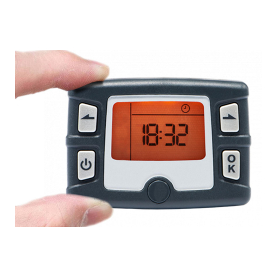
HEATPORT H2000 / H55 / W5S / W90
DiGiCon
HEATPORT is the brand name of the New Zealand based family owned company LF Bros NZ Pty Limited with its own design,
development, testing, assembly, quality check, installation and service facility located in Cheviot / North Canterbury.
Our mission is to bring the ultimate premium quality diesel heating system that everyone can afford.
We think about every single detail of the product. These details are mostly hidden from people but we know that the continual
improvement of all of these components with no compromise on the selection of the parts and quality is the only way to offer
the long lasting, easy to use product, best customer experience, and gain our customers trust.
Made in New Zealand
Version 1.2 - 08/2022
Advertisement

Summary of Contents for Heatport H2000
- Page 1 HEATPORT H2000 / H55 / W5S / W90 DiGiCon HEATPORT is the brand name of the New Zealand based family owned company LF Bros NZ Pty Limited with its own design, development, testing, assembly, quality check, installation and service facility located in Cheviot / North Canterbury.
- Page 2 1. INTRODUCTION Thank you for purchasing your HEATPORT diesel heater. For a better understanding of how to operate your heater efficiently please read this user manual. Note: Not all the functions may be available for each model of the heating systems.
-
Page 3: Main Menu Symbols
MAIN MENU SYMBOLS Simple Heating - Heating in 2 optional modes - fixed power / thermostatic Ventilation mode - only the fan is spinning and blowing cold air Ambient measurement - shows actual temperature and pressure 7 day programmable timer - set when you want to start your next heating cycle Time - set date, time and advanced settings 2. -
Page 4: Operation
3. OPERATION IMMEDIATE HEATING ○ This mode is used for manual ON and OFF switching of heating with preset power or at designated temperature. ○ Select using and confirm with ○ You can adjust heating power between 1 to 7 with arrows. ○... - Page 5 AMBIENT TEMPERATURE AND PRESSURE ○ This will show you the temperature of air coming through the heater and air pressure. ○ Select using arrows and confirm with ○ Air temperature will display on the display, for air pressure press ○ To get back to the main menu press Note: For quicker selection and changes in the menu you can just hold the arrow instead of pressing it multiple times.
- Page 6 Example: You want the heater to be running every working day between 6am and 1pm and every Wednesday and Saturday between 5pm and 9 pm. You first set up the program number 1, switch it on. You set the duration of the heating for 420 minutes (7hours) and the start of the heating will be at 6:00. You set it ON for Monday-Friday and OFF for Saturday and Sunday.
- Page 7 Example: You want to set the brightness of the display to half of maximum power. You select settings, press both arrows together. Now you are in the P1 menu, confirm with OK, with an arrow select C2 menu, confirm with OK and select 00 menu to get into the brightness settings.
- Page 8 4. FAULT CODES / TROUBLESHOOTING Note: This fault code book is designed for an easy identification of any issue. Any repairs/replacements of the internal components of the heater unit described below must be consulted and pre-approved first with the supplier of the product. The warranty will be voided if there are any repairs/modifications or unauthorized changes in the hardware or firmware of the product without the approval of the supplier or any replacement of non-original parts or components that are not supplied by the supplier.
- Page 9 positive and negative terminal at the wiring harness. Fault of wiring harness ● Inspect wiring for damage or short circuiting with the chassis of the vehicle. ○ Check continuity from the ECU board to the connector of the Main Controller. In case of wrong connection, replace a wiring harness.
- Page 10 Fault of the wiring harness * please see above ● Fault of the Fuel Pump * please see above ● Fault of the ECU * please see above ● FUEL PUMP Fuel pump broken circuit ● Wrong connection in connectors ●...
- Page 11 ELECTRONIC Fault of the crystal oscillator in the ECU ● CONTROL UNIT Incorrect ECU / Main Controller ● Replace ECU / Main Con ○ ELECTRONIC Fault of the memory in the ECU ● CONTROL UNIT Incorrect ECU / Main Controller ●...
- Page 12 No part of this manual may be copied or reproduced in any form without the express permission of HEATPORT. This publication was correct at the time of going to print; however, HEATPORT has a policy of continuous improvement and reserves the right to amend any specifications without prior notice.

Need help?
Do you have a question about the H2000 and is the answer not in the manual?
Questions and answers