Table of Contents
Advertisement
Quick Links
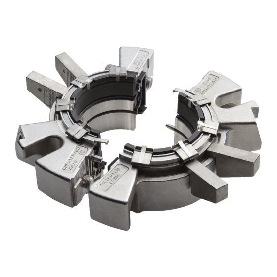
442 C
™
Split Mechanical Seal
Installation, Operation and Maintenance Instructions
Seal Data Reference
(Insert seal and equipment data here for future reference)
(Example: 442C - 50 mm SSC/CB)
Cartridge
INSTALLATION, OPERATION and
MAINTENANCE INSTRUCTIONS
TABLE OF CONTENTS
TABLE
1.0
1.0
Caut
Cautions ................................................................... 2
2.0
2.0
Transport and Storage ......................................... 2
Tran
3.0
3.0
Description .............................................................. 2
Desc
3.1 Parts
3.1 Parts identification ..........................................................2
3.2 Opera
3.2 Operating parameters .....................................................3
3.3 Intend
3.3 Intended use ..................................................................3
3.4 Dimensional Data ..................................................... 4 - 5
3.4 Dime
4.0
4.0
Preparation for Installation ........................... 6 - 8
Prep
4.1 Equip
4.1 Equipment .....................................................................6
4.2 442C Cartridge Split Mechanical Seal ..............................8
4.2 442C
5.0
5.0
Seal
Seal Installation .............................................9 - 11
5.1 442C
5.1 442C Installation Video .................................................11
6.0
6.0
Com
Commissioning/Equipment Start-up ............. 11
7.0
7.0
Deco
8.0
8.0
Spare Parts ........................................................... 11
Spar
9.0
9.0
Seal
Seal Maintenance and Repair ................ 12 - 16
9.1 442C
9.1 442C Seal Repair Instruction Video ................................16
9.2 Retur
Hazar
Hazard Communication Requirements ...........................16
Advertisement
Table of Contents

Related Manuals for Chesterton 442C

Summary of Contents for Chesterton 442C
-
Page 1: Table Of Contents
3.4 Dimensional Data ............. 4 - 5 3.4 Dime Preparation for Installation ......6 - 8 Prep 4.1 Equipment ..............6 4.1 Equip 4.2 442C Cartridge Split Mechanical Seal ......8 4.2 442C Seal Installation ..........9 - 11 Seal 5.1 442C Installation Video ..........11 5.1 442C Commissioning/Equipment Start-up ..... -
Page 2: Cautions
These decisions are to be made by the user. The decision to use this seal or any other Chesterton seal in a particular service is the customer’s responsibility. TRANSPORT AND STORAGE Transport and store seals in their original packaging. -
Page 3: Operating Parameters
(710 mm Hg /28") to the maximum pressures at the application and/or outside the operating parameters, consult conditions listed. Chesterton to confirm the suitability of the mechanical seal prior to putting the mechanical seal in operation. Small Sizes: 25 mm through 60 mm (1.000" through 2.500") Reaction Bonded Silicon Carbide/Carbon –... -
Page 4: Dimensional Data
DESCRIPTION cont. 3.4 Dimensional Data (Drawings) Figure 2 P NPT P NPT KEY (chart) A – Shaft Size Table 1 - Dimensional Data (Metric & Inch) B – Max. Gland Dia. C – Min./Max. Stuffing Box Dia. SHAFT SIZE HOLDER ID INSTALLATION SHAFT O-RING SET SCREW... - Page 5 DESCRIPTION cont. Table 2 – Dimensional Data METRIC - Millimeters G MIN 8 mm 10 mm 12 mm 14 mm 16 mm 18 mm 20 mm 25,0 125,5 47,2 53,3 40,1 47,8 79,8 81,8 83,8 85,8 87,8 59,9 70,9 30,0 125,5 47,2 53,3...
-
Page 6: Preparation For Installation
PREPARATION FOR INSTALLATION 4.1 Equipment < ø < .005" 0,13 mm 125 μ" 3,2 μm ø If practical, place the dial indicator tip on the end of the shaft If possible, attach a base dial indicator to the shaft and rotate sleeve or on a step in the shaft to measure end play. -
Page 7: 442C Cartridge Split Mechanical Seal
PREPARATION FOR INSTALLATION cont. 4.2 442C Cartridge Split Mechanical Seal Review seal packaging ensuring no damage or shortage has occurred to the contents. Review the seal fit dimensions in Tables 1, 2 and 3 to ensure the equipment to be sealed has the required dimensions. - Page 8 PREPARATION FOR INSTALLATION cont. Remove seal from packaging and place Disengage rotary holder screws and Remove rotary holder shipping spacer on clean work surface. Ensure installation separate rotary holder halves. from each holder half by pulling on tab; spacers are seated on OD of rotary holder retain for future use.
-
Page 9: Seal Installation
SEAL INSTALLATION Bring holder assembly halves together Use hex wrench and alternately tighten Push holder assembly so that plastic over shaft, engaging the pins. Note: If holder cap screws to finger-tightness to installation spacers contact the stuffing shaft cannot be rotated manually, the allow holder to slide. - Page 10 5.0 SEAL INSTALLATION 90° Apply a thin film of grease to both split If stationary face is clean no additional Position the gland splits approximately 90 surfaces of one stationary face half. cleaning is required. Otherwise wipe degrees from the rotary holder splits. stationary face with cleaning wipe, ensuring that there is no debris at splits.
-
Page 11: 442C Installation Video
Ensure that the pump is isolated and check that the stuffing box is drained from any fluid and pressure is fully released. Disassemble the 442C split seal and remove from equipment in the reverse order from installation instructions. -
Page 12: Seal Maintenance And Repair
SEAL MAINTENANCE AND REPAIR A correctly installed and operated mechanical seal requires little 2. The following items, in addition to wrenches, grease and maintenance. It is recommended to periodically check the seal cleaning wipes, will be required for rebuild: for leakage. Wearing components of a mechanical seal such as •... - Page 13 SEAL MAINTENANCE AND REPAIR cont. Remove used gland gaskets from gland Remove used spring retainers from gland Remove used stationary face O-ring. grooves. halves. NOTE: When last retainer is removed the stationary seal ring can be removed Remove used stuffing box gasket from Remove used springs from gland halves Remove spring lifter halves from gland gland face and all adhesive residue with...
- Page 14 SEAL MAINTENANCE AND REPAIR cont. Install rotary holder shipping spacers in Apply a thin film of grease and install Install rotary face halves in rotary holder rotary holder halves. rotary face O-ring halves in rotary holder halves. Press on face to seat rotary in halves.
- Page 15 SEAL MAINTENANCE AND REPAIR cont. Install new gland cap screws in gland Apply a thin film of grease to the Install stationary face halves into gland halves. Note: Gland cap screws are stationary face O-ring halves and install in halves. installed in one end of each gland gland halves;...
-
Page 16: 442C Seal Repair Instruction Video
SEAL MAINTENANCE AND REPAIR cont. 9.1 442C SEAL REPAIR INSTRUCTION VIDEO To view an instructional video on how to repair the 442C, please scan the QR Code with your mobile device or go to our web page at www.chesterton.com/442C_Videos and click on the desired video.
Need help?
Do you have a question about the 442C and is the answer not in the manual?
Questions and answers