Table of Contents
Advertisement
Quick Links
Advertisement
Table of Contents

Related Manuals for Xtool IK618


Summary of Contents for Xtool IK618
- Page 1 User Manual IK618 Key Programming Tool Shenzhen Xtooltech Intelligent Co., LTD...
-
Page 2: Copyright
CO., LTD. In countries where the trademarks, service marks, domain names, logos and the name of the company are not registered, XTOOL claims that it still reserves the ownership of the unregistered trademarks, service marks, domain names, logos and the company name. All other marks for the other products and the company’s name mentioned in the manual still belong to... -
Page 3: Operation Instructions
XTOOL. Use the device only as described in this manual. XTOOL is not responsible for any consequences of violating the laws and regulations caused by using the product or its data information... -
Page 4: Cautions
AUTIONS ⚫ Avoid shaking or dismantling the unit as it may damage the internal components. ⚫ Do not use hard or sharp objects to touch the LCD screen; ⚫ Do not use excessive force; ⚫ Do not expose the screen to strong sunlight for a long period. ⚫... -
Page 5: Table Of Contents
Package List ..................5 GETTING STARTED ..............6 Activation ..................... 6 Main Interface ..................8 Operation system ........................8 IK618 APP Menu ........................9 Function Buttons ........................10 Navigation Buttons ........................ 11 Notification Bar ........................12 UPDATE ................. 13 KEY PROGRAMMING ............14 Vehicle Connection ................ - Page 6 Check Number of Keys ......................20 Add Keys ........................... 21 All Key Lost ..........................23 DIAGNOSTIC ................. 29 Diagnostics ..................29 Vehicle Selection ........................29 Diagnosis functions........................ 32 SPECIAL FUNCTIONS ............41 5.1 OIL RESET .................. 41 5.2 EPB ....................43 5.3 SAS ....................
- Page 7 Q7: How to switch language .............. 74 Q8: SHOWING “COMMUNICATION FAILED” ........75 Q9: Failed to activate or register ............75 Q10: Failed to turn on when charging ..........75 Q11: Failed to open the Diagnostic app ..........76 Q12: HOW TO FACTORY RESET THE DEVICE ......76 Q13: SHOWING “LICENSE EXCEPTION”...
-
Page 8: General Introduction
EEPROM adapter, allows you to generate dealer keys, read key remote frequency, and modify EEPROM data on bench. TABLET The main unit of the IK618 is the tablet, which can be directly connected to the tablet and the car with the test cable. FRONT VIEW OF TABLET ②... -
Page 9: Back View Of Tablet
② Touch Screen: Shows the info from the device and allows you to operate the device. BACK VIEW OF TABLET ② ① ② ① Nameplate: Shows basic info for the device like serial number, safety info, etc. ② Loudspeaker: Use as sound/voice output. HOST PORTS ①... -
Page 10: Accessories
KC100 is a transponder generator that is used to generate dealer key for Volkswagen/Audi/BMW/Fiat/Renault and more models. It can also be used to generate emulated keys, write transponder chips and read remote frequency. KC100 has to be used with IK618. ① ⑤... -
Page 11: Eeprom Adapter
④ Frequency detection area: Put the key here to test remote frequency. ⑤ Mini USB port: Connects to the device. EEPROM ADAPTER EEPROM Adapter allows you to read and write the data from the EEPROM chip of the immobilizer module, dashboard and other modules. ①... -
Page 12: Package List
⚫ Wired Gravity sensor, light sensor Sensors Microphone, dual speakers Auto Input/Output 5000mAh, 3.65V lithium-polymer battery Power and Battery Power Voltage Power Consumption -20 to 60℃(-4 to 140℉) Operating Temperature -40 to 70℃(-40 to 158℉) Storage Temperature <90% Humidity 249*142*33.5mm Dimension (L*W*H) PACKAGE LIST Category... -
Page 13: Getting Started
ETTING TARTED ACTIVATION After first-time users press and hold the power button to turn on the system, the system will automatically enter the guide process and request to select the language for the operating system. After setting the system language, you will enter the activation page, as shown in the figure below. - Page 14 Click Start Activate to enter the activation page, as shown below: A pop-up window showing Activation Success indicates that you have completed the first boot setup, click OK to enter the diagnostic system and start using the device. After factory reset the device, you will need to reactivate it again. Please note that the subscription will not be refreshed after reset.
-
Page 15: Main Interface
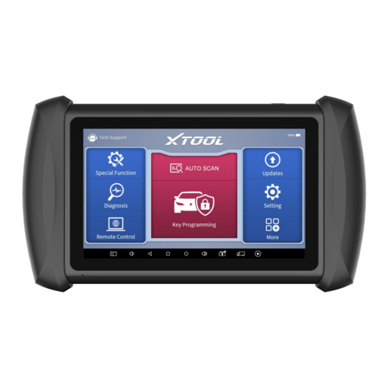
MAIN INTERFACE OPERATION SYSTEM As shown in the figure below, this interface is the main page of the operating system of the device. You can also return to this interface at any time by clicking 【⚪】on the bottom navigation bar. The icons on the right, from top to bottom, are browser, photo album, application square, file manager, system settings, as shown below: Items... -
Page 16: Ik618 App Menu
Android system, including network, battery status, language, device info and factory reset. IK618 APP MENU Once activated, you will automatically enter the IK618 app with the following main screen. Tap on the Diagnostic application button on the menu, the main interface will be shown as below:... -
Page 17: Function Buttons
The main screen contains Function Buttons and Navigation Buttons. The touch screen navigation is menu-driven, and you can quickly access functions by clicking on the option title and answering the dialogue window. A detailed description of the menu structure can be found in the next section Function Buttons. -
Page 18: Navigation Buttons
Enter settings menu to change settings in the app Setting Contain more options, like XTOOL, where you can check Xtool official website for full support list, check user manual More and other details Check the diagnosis report that recorded in your device,... -
Page 19: Notification Bar
Increase volume Showing the Bluetooth states Click this button to return to the diagnostic vehicle interface Press for screen recording NOTIFICATION BAR Slide down to open the notification bar. You can adjust the brightness of the screen when needed, and you can also connect Wi-Fi and so on. -
Page 20: Update
After contacting your dealer to change the language configuration, please download all the software packages on the device again. IK618 has a two-year free subscription when activated. When you click “update” and it shows “your device is now out of subscription”, please contact your dealer. -
Page 21: Key Programming
ROGRAMMING The key programming software inside IK618 app can get access to the immobilizer system inside the vehicles and supports multiple functions like key programming, generate dealer key, all key lost, immobilizer reset or changing, EEPROM chip coding and much more. -
Page 22: Connect To Kc100
Find the cable that connects Mini USB and USB 3.0. Connect the Mini USB socket into the bottom of KC100 and connect the USB 3.0 socket into the IK618. When the light turns on, you can perform the functions. CONNECT TO EEPROM ADAPTER In order to read EEPROM chips using the EEPROM Adapter, please follow the steps below. -
Page 23: Immobilizer Menu
IMMOBILIZER MENU Click “Key Programming” icon on the main screen and get into the immobilizer menu. Choose the brand of the vehicle to start the programming process. You can also click the search icon on the top-right corner of the screen and find the brand you need. ... -
Page 24: Immobilizer Functions
IMMOBILIZER FUNCTIONS Normally the key programming software supports these functions: ⚫ Check number of keys ⚫ Read PIN code/pin code calculation ⚫ Add key ⚫ Generate dealer key ⚫ All key lost And more… Some examples will be provided in this manual to help you understand the process. - Page 25 Please choose the type of your vehicle. If you have any questions, please click “Help” for more details. Here we choose “Type 1”, then insert the 5-digit BCM code. The BCM for Nissan vehicles may be found under the steering wheel, behind the glove box, behind the passenger/driver side kick panel and behind dash cluster - depending on the model of vehicle.
- Page 26 After you inserted the code, the results will show up. Quick Tip: If you have trouble working on Nissans, please change the language into English, check the updates and see if there is a “NISSAN PIN DATA”. Usually download it will solve the problem.
-
Page 27: Check Number Of Keys
CHECK NUMBER OF KEYS Here we take a 2020 Honda Accord with smart key as an example. Click “Immobilization – Honda – By vehicle – Accord – Smart key – Button type” to enter the system, then this menu will show up. Click “Number of read keys”... -
Page 28: Add Keys
ADD KEYS Still take the 2020 Honda Accord as an example. Click “Add smart key” menu, then check the notice from the screen. Because this vehicle is paired with smart keys, we need to take all the keys out from the vehicle before programming, then put the original key inside the car. - Page 29 Now the system will configure the data and after it’s done, take the smart key out from the car first. Then take a new key and put it into the car. Then it will start processing. You need to follow the instructions and turn the ignition on and off for several times when processing.
-
Page 30: All Key Lost
If it really goes off, press “Yes”, wait for a while, and the process will be done. ALL KEY LOST Still take the 2020 Honda Accord as an example. Click “All smart keys lost” menu and this notice will show up. Follow the instructions and take all the keys out from the car, then click “OK”... - Page 31 Then put one of the new keys inside the car. As before it will check if the ignition could be turned on when you double- clicked the start button. Since we don’t have a programmed key in an all- key-lost situation, we click “No” here.
- Page 32 Then press and hold the start button, and press “OK” to continue. After that, please check the ignition status. Same as before, we click “No” here.
- Page 33 Then it will check the model. Because this is a 2020 model, we select “Yes” here. Now input the number of keys you’re going to program; we choose 1 here.
- Page 34 Like the “add key” process, it needs you to turn the ignition on and off for several times. After that, check security light of the dashboard. Then the instructions will tell you to turn the ignition on and off again. It will show “Program success”...
- Page 35 We suggest checking all the keys every time after you programmed the key.
-
Page 36: Diagnostic
DIAGNOSTICS After the tablet device is properly connected to the vehicle, you could start the vehicle diagnosis. VEHICLE SELECTION The IK618 supports the following 3 ways to access the smart diagnostics system. ⚫ AUTO SCAN ⚫ MANUAL INPUT ⚫... - Page 37 Click the VIN button in the upper left corner, you can choose to enter the vehicle diagnosis through the first 2 ways of AUTO SCAN/ MANUAL ENTER. AUTO SCAN: It supports automatic reading of vehicle VIN code. You also can tap on the button “AUTO SCAN” on the diagnosis system entrance to use this function.
- Page 38 ⚫ SELECT VEHICLE BY AREA In addition to the above 3 methods, you can also choose a car brand according to the region. You can select the vehicle model that needs to be diagnosed according to the area, as shown below:...
-
Page 39: Diagnosis Functions
Enter "System Selection", you can also diagnose the vehicle according to the system according to your needs after selecting the model. DIAGNOSIS FUNCTIONS Diagnostics functions supported by IK618 Smart Diagnostics System are as below:: ⚫ Read ECU Information ⚫... - Page 40 ⚫ READ ECU INFORMATION This function is to read ECU version information, which is the equivalent of "System Identification" or "System information in some electronic control systems, all mean to read ECU related software and hardware versions, models and production date of diesel engine, part number, etc. It is convenient for us to make a record in the maintenance process, and it also makes data feedback and management easier.
- Page 41 ※NOTE: In the process of diagnosis, if the device shows “System is OK” or “No Trouble Code”, it means there is no related trouble code stored in ECU or some troubles are not under the control of ECU, most of these troubles are mechanical system troubles or executive circuit troubles, it is also possible that signal of the sensor may bias within limits, which can be judged in Live Data.
- Page 42 The trouble codes can’t be erased without eliminating all the troubles, which will cause the diagnostic tool to always read the trouble code because the code will always be saved in ECU. Suggestion: users should better not clear trouble codes, we need to record the trouble details after reading the code, which is provided as a reference for maintenance.
- Page 43 ⚫ Custom Support to show the selected PIDs. Click Display All, back to the page which display all PIDs ⚫ Combine Support to select multiple PIDs and click Combine to make different graphs into one chart.
- Page 44 ⚫ Data recording Supports recording the current data value in the form of text, you can view the recorded files in Reports->Data Replay.
- Page 45 ⚫ Pause Click this button to pause the timeline ⚫ FREEZE FRAME When the signal of the sensor is abnormal, the ECU will save the data at that moment of failure to form a freeze-frame. It is usually used to analyze the reasons that may lead to car failures.
- Page 47 Context when fault appeared: record the live data when fault appeared to help the user to know the vehicle status. *Some vehicles don't support this function; users will get a prompt when they click the menu. Current context: Displays the current live data stream associated with the Additional data: record other data related to the fault...
-
Page 48: Special Functions
PECIAL UNCTIONS The IK618 Smart Diagnostic System supports 25 commonly used special reset functions, allowing you to quickly access your vehicle system for various scheduled services, maintenance, and reset performance, eliminating the need to reset after resolving common problems. This user manual lists some of the commonly used special reset services for your reference. - Page 49 cycle. ⚫ After changing engine oil or electric appliances that monitor oil life, you need to reset the service lamp. The operation guidelines of the Oil Reset function are shown as below: Enter the Oil Reset menu and choose relevant models according to the vehicle being tested.
-
Page 50: Epb
Message of ‘Reset success’ displayed when Oil Reset function has successfully performed. 5.2 EPB Electronic Parking Brake (EPB) System reset is a popular special function. You can use this function to reset the electronic parking brake system and brake pads, which also supports the brake pad replacement (retraction, release of the brake pump), G-sensor, and body angle calibration. - Page 51 ⚫ The brake pad and brake pad wear sensor are replaced. ⚫ The brake pad indicator lamp is on. ⚫ The brake pad sensor circuit is short, which is recovered. ⚫ The servo motor is replaced. The operation guidelines of the EPB function are shown as below: Enter the EPB menu and choose relevant models according to the vehicle being tested.
-
Page 52: Sas
Wait until the message of ‘Successful operation’ popes up. And press OK to exit the menu. Enter the Exit maintenance mode menu and wait until the message of ‘‘Successful operation’ popes up. 5.3 SAS Steering Angle Sensors (SAS) System Calibration permanently stores the current steering wheel position as the straight-ahead position in the SAS EEPROM. - Page 53 The operation guidelines of the SAS function are shown as below: Enter the SAS menu and choose relevant models according to the vehicle being tested. Enter the Set steering angle sensor menu and follow the instructions displayed. Wait until the following instruction is displayed and press Yes after completing the instructions shown.
- Page 54 instructions shown. Wait until the following instruction is displayed and press OK after completing the instructions shown. Message of ‘Function execution is completed’ displayed when SAS function has successfully performed.
-
Page 55: Dpf
5.4 DPF The Diesel Particle Filter (DPF) function manages DPF regeneration, DPF component replacement teach-in, and DPF teach-in after replacing the engine control module (ECM). The ECM monitors driving style and selects a suitable time to employ regeneration. Vehicles driven a lot at idling speed and low load will attempt to regenerate earlier than vehicles driven more with higher load and speed. - Page 56 Read the fuel tank level and make sure that it fulfills the requirement displayed. Read the carbon deposit load. Choose the drive to warm up and follow the instructions listed below. And press OK after completing the instructions shown. Read the note carefully and follow the instructions shown on the screen. And press OK after completing the instructions shown.
- Page 57 Follow the instructions displayed and press OK after completing the instructions shown. Please pay attention to the Note. Press the OK button to start the regeneration.
- Page 58 10. Wait for the value of carbon deposit to decrease until a message of ‘Emergency regeneration has been completed’ popes up, this process may take up to 40 minutes.
-
Page 59: Bms Reset
11. Wait for 2 minutes to let the particulate filter cool down. 12. Press drop out to exit the DPF function. 5.5 BMS RESET The Battery Management System (BMS) allows the scan tool to evaluate the battery charge state, monitor the close-circuit current, register the battery replacement, and activate the rest state of the vehicle. - Page 60 can avoid an error message displayed on the instrument cluster. The operation guidelines of the BMS Reset function are shown as below: Enter the BMS Reset menu and choose relevant models according to the vehicle being tested. Turn on the ignition switch. Press OK to continue the BMS function.
-
Page 61: Throttle
Enter the 10-digit battery serial number and press OK after the input. 5.6 THROTTLE Throttle Position Sensor (TPS) Match, this function enables you to make initial settings to throttle actuators and returns the “learned” values stored on ECU to the default state. Doing so can accurately control the actions of regulating throttle (or idle engine) to adjust the amount of air intake. - Page 62 Enter the Throttle menu and choose relevant models according to the vehicle being tested. Enter the Auto Recognition menu and turn on the ignition switch. Read carefully and complete the requisites listed before performing the throttle regeneration function. And press OK after completing the instructions shown.
-
Page 63: Injector Coding
pops up. 5.7 INJECTOR CODING This function can write the identification code of the fuel injector into the ECU so that the ECU can recognize and work normally. Write actual injector code or rewrite code in the ECU to the injector code of the corresponding cylinder for controlling accurately and correcting cylinder injection quantity. - Page 64 Read and confirm the value stored in the cylinders. Enter the Change the value of cylinder menu of the replaced injector(s), enter the new 5-digit value, and then press OK.
-
Page 65: Gearbox Match
Wait until the message ‘Write successfully’ pops up. Turn off the ignition switch. Wait until the message asked you to turn on the ignition switch. Re-enter the Fuel injection nozzle injection volume adjustment menu to check whether the new value(s) are shown. 5.8 GEARBOX MATCH After changing the gearbox or changing the gearbox ECU, you need to use the gearbox matching function to re-match the engine and the gearbox. -
Page 66: Gear Learning
Before resetting the gearbox, please check the gearbox control unit to ensure that there is no fault code. If there is a fault code, the gearbox memory function cannot be reset. Please road test after reset. The operation guidelines of the Gearbox Matching function are shown as below: Enter the Gearbox matching menu and choose relevant models according to the vehicle being tested. - Page 67 MIL turns off. This function can complete the self-learning of the gearbox and improve the quality of shifting. After the engine ECU, crankshaft position sensor, or crankshaft flywheel is replaced, or the DTC 'gear not learned' is present, gear learning must be performed.
-
Page 68: Eeprom Adapter
ETTINGS Click the Settings button to adjust the default settings and view information about the IK618 Smart Diagnostic System. There are seven options available in the system settings: ⚫ Language ⚫... -
Page 69: Language
⚫ My Workshop Info ⚫ VCI Info ⚫ About LANGUAGE The languages supported by this device are listed in Settings. In areas outside the English area, the default language is English and the local official language. Users can switch between English and local official languages on the device by themselves. -
Page 70: Units
Step4: Back to Updates to pull all packages again UNITS You can switch the unit used by the system. IK618 Smart Diagnostic System provides you with Metric, Imperial, and U.S. units. You can directly click on the unit you need, after the switch is successful, a blue checkmark will be displayed behind the unit’s name. -
Page 71: Firmware Information
FIRMWARE INFORMATION You can view the firmware information here, including the firmware name, the latest firmware version, the currently used firmware version, and the VCI firmware type. The Diagnostic tablet supports automatic firmware update, please make sure that the device is connected to the network when you enter the diagnostic software and the firmware will be automatically updated to the latest version. -
Page 72: About
ABOUT Tap on ABOUT, you can check the serial number and APP version on here. -
Page 73: Report
EPORT Diagnostic Report is used for viewing and printing the saved files, such as Live Data, Trouble codes or pictures generated in the process of Diagnostic, users also can view a record of which cars have been previously tested. It includes 3 parts: ⚫... - Page 74 When you open the report, located in the header of the table is the studio information you filled in advance in the system setup, then the information of the vehicle, as shown as below:...
- Page 75 IP address of the printer in the APP, or you can contact your dealer for help. IK618 Smart Diagnostic System doesn’t provide the printer driver software, please install a third part App on the tablet if you need the print your Diagnostic report.
-
Page 76: Replay
REPLAY This function allows you to replay the living data recorded during the Diagnostic process. Before replaying the living data, please make sure you have recorded the live data during the Diagnostic FILE MANAGER This function allows you to check and delete files on the device. Please use this function under the guidance of professionals. -
Page 77: Remote Assistance
4. Provide your ID to the partner or XTOOL technician, and then wait for him/her to send you a remote-control request. 5. A pop-up window will be displayed, asking you to confirm to allow the... - Page 78 To fix that, Open the web browser using the device, and it will guide you to XTOOL official website. Click “Support – Download Center”, find Teamviewer and click download. After you have downloaded the apk...
-
Page 79: Faq
10 FAQ Q1: FAILED TO GENERATE DIAGNOSTIC REPORT 1. Currently this could only be used when performing diagnostic functions, like read ECU information, read code and clear code, live data, freeze frame, which can trigger a diagnostic report. Other functions, such as immobilization and maintenance services will not be displayed in the report. -
Page 80: Q2: How To Print Diagnostic Report
OS settings. After the setting is completed, you can print it in the Report. Q3: FAILED TO EXTRACT FILES Since the XTOOL tablet is equipped with an Android system, you have to confirm the system type of receiver. -
Page 81: Q4: Mailbox Supported
Q6: HOW TO GENERATE AND UPLOAD DIAGNOSTIC LOG FILES The IK618 tablet will automatically generate and store the diagnostic logs. When the device is connected to the Internet, it will automatically upload all the stored diagnostic logs to the backend system. -
Page 82: Q8: Showing "Communication Failed
Q8: SHOWING “COMMUNICATION FAILED” 1. Contact your dealer to confirm whether the vehicle model is supported by the scan tool you owned. 2. Check whether the vehicle is properly connected (e.g. whether the ignition is ON, and the Diagnostic of some vehicle need to turn on the engine ), If your tablet is equipped with a VCI box, please check the status of VCI box indicator. -
Page 83: Q11: Failed To Open The Diagnostic App
If this happened on all the software, try delete all the diagnostic files this device. And if it still doesn’t work, please contact Xtool aftersales services. Q14: SHOWING “FAILED” WHEN GOING INTO MENUS Try delete and re-install the software. -
Page 84: Q16: Some Of The Software Are Missing
3. Factory reset the device, and tick “Erase SD card” before you start. Before you do that, make sure you are in subscription and can download the software updates. Also, if you meet these issues frequently, you can avoid them by regularly delete some of the software that are not commonly used, or delete download folder regularly and do not download too many of them. - Page 85 This equipment has been tested and found to comply with the limits for a Class B digital device, pursuant to Part 15 of the FCC Rules. These limits are designed to provide reasonable protection against harmful interference in a residential installation. This equipment generates uses and can radiate radio frequency energy and, if not installed and used by the instructions, may cause harmful interference to radio communications.
-
Page 86: Ukca
Declaration of conformity Herby, Shenzhen Xtooltech Intelligent Co., Ltd declares that this Car Diag nostics Tablet, P710 complies with the essential requirements and other relevant provisions of Directive 2014/53/EU. By Article 10(2) and Article 10(10), this product is allowed to be used in all EU member states. UKCA Herby, Shenzhen Xtooltech Intelligent Co., Ltd declares that this Car Diag nostics Tablet P710 satisfies all the technical regulations applicable to the... - Page 87 SHENZHEN XTOOLTECH INTELLIGENT CO., LTD COMPANY ADDRESS: 17&18/F, BUILDING A2, CREATIVITY CITY, LIUXIAN AVENUE, NANSHAN DISTRICT, SHENZHEN, CHINA FACTORY ADDRESS: 2/F, BUILDING 12, TANGTOU THIRD INDUSTRIAL ZONE, SHIYAN STREET, BAOAN DISTRICT, SHENZHEN, CHINA SERVICE-HOTLINE: 0086-755-21670995/86267858 EMAIL: MARKETING@XTOOLTECH.COM FAX: 0755-83461644 WEBSITE: WWW.XTOOLTECH.COM...
Need help?
Do you have a question about the IK618 and is the answer not in the manual?
Questions and answers