Table of Contents
Advertisement
Quick Links
CVS Type 67AFR Filter
Regulator
Introduction
This CVS Controls product manual includes
instructions for the installation, adjustment,
maintenance and parts ordering of the CVS Type
67AFR Filter Regulator.
All CVS Controls equipment should be installed,
operated and maintained by qualified personnel. If
you have any questions regarding this equipment,
contact your CVS Controls representative.
Ensure that the label of the control spring range is
updated to reflect any changes in field equipment,
materials, service conditions or pressure settings.
If any venting occurs or a leak develops in the
pressure system this indicates that service is
required. Failure to remove the regulator from
service for immediate maintenance may cause a
hazardous situation.
These regulators are often shipped installed on
other equipment. Information on that equipment
will be contained in separate manuals.
Description
The CVS Type 67AFR Filter Regulator is a self-
operated unit which provides continuous reduced
pressures in a variety of applications and service
conditions. Common use is as supply pressure
regulators for pneumatic instruments.
A cellulose filter is used with the CVS Type 67AFR
Filter Regulator and will remove particles greater
than 0.0016 inch (0.040 mm) in diameter.
In addition, these regulators contain integral low-
capacity relief valves. In this type of construction
the valve stem
Australian Agents
www.globalsupplyline.com.au
sales@globalsupplyline.com.au
Product Manual
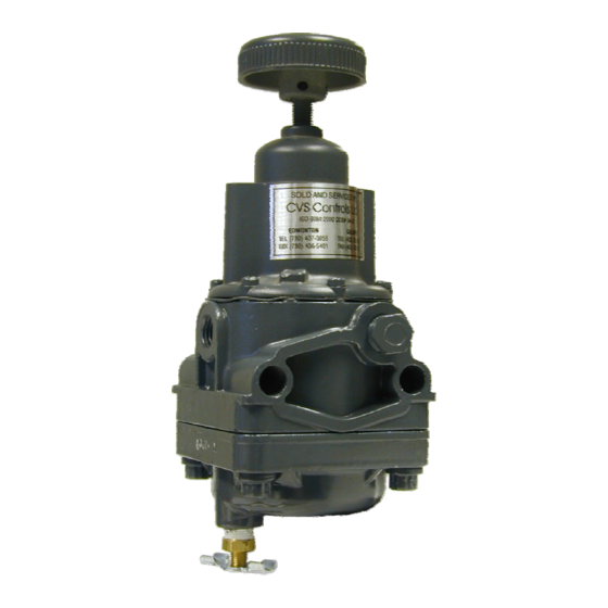
Figure 1: CVS Type 67AFR Regulator
sits against an orifice in the diaphragm assembly.
When downstream pressure increases above the
set point, the diaphragm assembly moves off the
valve stem and excess pressure is vented through
a port hole tapped in the spring case.
Installation
Warning
Do not install any pressure equipment where
service conditions exceed the manufacturer's
specifications. Over pressuring of regulator
may result in leakage, equipment damage or
injury. Excessive pressure can cause the
pressure-containing parts to burst, or
accumulated gas to explode. The CVS Type
67AFR Filter Regulator cannot be used with
hazardous gas unless vented to a safe area.
1
Advertisement
Table of Contents

Subscribe to Our Youtube Channel
Related Manuals for CVS Controls 67AFR


Summary of Contents for CVS Controls 67AFR
- Page 1 Over pressuring of regulator may result in leakage, equipment damage or A cellulose filter is used with the CVS Type 67AFR injury. Excessive pressure can cause the Filter Regulator and will remove particles greater pressure-containing parts to burst, or than 0.0016 inch (0.040 mm) in diameter.
- Page 2 As with many regulators, the outlet pressure rating filter cap (Key 9). Prevent plugging of the spring on the CVS Type 67AFR Filter Regulator is lower case vent and keep the spring case from than the inlet pressure rating. If it is possible for...
-
Page 3: Maintenance
CVS Controls Ltd Product Manual: CVS Type 67AFR Filter Regulator Installation continued CVS Controls sets each regulator for the pressure 5. If vent valves have not been installed, safely bleed off inlet and outlet pressure and ensure setting specified at the time of ordering. If no setting was indicated, the outlet pressure will be that the regulator contains no pressure. -
Page 4: Parts Ordering
Parts Ordering Maintenance continued To access the valve plug (Key 6) or filter element To help CVS Controls assist you better, include the (Key 15) for replacement or cleaning: regulator type number and other important data stamped on the bottom of the filter cap and on the 1. - Page 5 CVS Controls Ltd Product Manual: CVS Type 67AFR Filter Regulator Parts List Key No. Description Part # Standard: Plated steel CVS1B798628982 Adjusting Screw Standard: Right Hand Thread, Zn CVS1B7992000A2 Handwheel (Optional) Right Hand Thread, Chrome Pl Steel CVS1U1715000C2 Locknut (not used with panel mounted regulators)
- Page 6 CVS Controls Ltd Product Manual: CVS Type 67AFR Filter Regulator Notes...
- Page 7 CVS Controls Ltd Product Manual: CVS Type 67AFR Filter Regulator Notes...
- Page 8 CVS Controls Ltd Product Manual: CVS Type 67AFR Filter Regulator Head Office Calgary Sales Office 3900 – 101 Street 205, 2323 – 32 Avenue NE Edmonton, Alberta, Canada T6E 0A5 Calgary, Alberta, Canada T2E 6Z3 Office: (780) 437-3055 Office: (403) 250-1416...
-
Page 9: Installation
Instruction Manual CVS Type 630 HP Regulators and Relief Valves Introduction Please note: These regulators and relief valves must be installed, operated and maintained in accordance with CVS instructions and all applicable federal, provincial, state and local codes, laws, rules, and regulations. -
Page 10: Overpressure Protection
Refer to the following tables to determine pressure Vents ratings: Spring-loaded constructions have a screened vent assembly (Key 24) installed in the ¼” NPT spring 1. Spring loaded Type 630 HP regulators case vent opening. If a remote vent is required, 1.1. - Page 11 Table 2: Outlet Pressure Limits for Spring-Loaded CVS Type 630 HP Regulators Low-Pressure Regulator High-Pressure Regulator 3 to 10 8 to 20 17 to 30 27 to 40 27 to 50 46 to 95 90 to 150 150 to 200 200 to 275 275 to 500 Outlet Pressure range...
- Page 12 Table 5: Relief Valve Pressure Limits for Pressure-Loaded CVS Type 630R Regulators Low Pressure Relief High Pressure Relief Valve Valve Loading Regulator Type Bellofram 7360 Bellowfram 7360 Bellofram P39 Max. Allowable Inlet Pressure to Relief pressure setting plus maximum Relief pressure setting plus maximum Relief Valve, PSIG Allowable buildup of 25 psig Allowable buildup of 250 psig...
- Page 13 6. To replace seating surface: Maintenance 6.1. For Type 630 HP, use a ¾” socket wrench to remove and re-install valve disc and holder assembly (Key 3). WARNING: To avoid personal injury and 6.2. For Type 630R, unscrew machine equipment damage, isolate the regulator or screw (key31) and remove O-ring relief valve from all pressure.
-
Page 14: Nameplate Information
Nameplate Information 9. To ensure proper slack in the diaphragm: When corresponding with your CVS Controls 9.1 For constructions using a spring, tighten the representative about this device, state the model spring case cap screws finger tight only. number, pressure range and all other pertinent Compress the spring slightly with the information found on the nameplate (Key 29). -
Page 15: Parts Reference
Parts Reference Description Body Valve Carrier Type 630R O-Ring Holder Type 630* Valve Disc Assembly Seat Ring Gasket (2 required) Inlet Adaptor, Steel Cap Screw, Steel (4 required) Gasket Pin, SST Lever Assembly Diaphragm Adaptor Connector Head Assembly Diaphragm, Neoprene Cap Screw, Steel Cap Screw, Steel Diaphragm Plate, Steel Cd. - Page 16 Figure 3: Spring-Loaded CVS Type 630R Relief Valve Low Pressure Connection Figure 4: Pressure-Loaded CVS Type 630R Relief Valve Low Pressure Connection...
- Page 17 Figure 5: Pressure-Loaded CVS Type 630 Regulator Low Pressure Connection...
-
Page 18: Parts List
CVS Type 630 HP Regulators and Relief Valves Parts List Description Part # 1” Cast Iron w/ brass pitot tube CVS0W0209000A2 1” Cast Iron w/ SST pitot tube CVS0W0209X0012 1” Steel w/ brass pitot tube CVS2N6990000A2 Body 1” Steel w/ SST pitot tube CVS2N6990X0012 2”... - Page 19 CVS Type 630 HP Regulators and Relief Valves Parts List cont’d Description Part # Spring See Following Table 630 Pressure Loaded None Required Pressure Range to 275 CVS0W019344022 Upper Spring Seat, Zinc 630 and 630R, and 630R Pressure Range over Pressure-Loaded CVS1K371144022 Cast Iron...
- Page 20 Key 23: Adjusting Screw, Steel For Wire Seal, Type Spring Use Adjusting Adjusting Screw Screw CVS0W019227022 CVS1A279128982 CVS1R829928992 CVS0W019127022 CVS1B212028982 CVS1R830028992 CVS0W019027022 CVS1A500528982 CVS1R808528992 CVS 630 CVS0Y0664000A2 CVS1A500528982 CVS1R808528992 CVS1J146927142 CVS1A500528982 CVS1R808528992 CVS1K370927082 CVS1A500528982 CVS1R808528992 None * CVS1C116227092 CVS0W019227022 CVS1A279128982 CVS1R829928992 CVS0W019127022 CVS1B212028982...
-
Page 21: Product Manual
CVS Type 1301F and CVS Type 1301G Regulator. All CVS Controls equipment should be installed, operated and maintained by qualified personnel. If you have any questions regarding this equipment, contact your CVS Controls representative. - Page 22 Approximate Weight 8 pounds (3.6 kg) Installation WARNING Prior to being shipped from CVS Controls, the Do not install any pressure equipment where pressure setting for each regulator is set service conditions exceed the manufacturer’s according to customer specifications. If no setting specifications.
- Page 23 CVS Controls Ltd Product Manual: CVS Type 1301F and 1301G Regulator Disassembly Start Up When the regulator has been installed and These steps describe how to completely disassemble downstream equipment has been adjusted, the the regulator. To perform inspection or replace parts, regulator can be pressurized.
- Page 24 Please refer to this information when corresponding was only partially disassembled, start at the with CVS Controls regarding parts or service for your appropriate step. Refer to Figure 2 for key numbers. CVS Type 1301F and CVS Type 1301G Regulator.
- Page 25 CVS Controls Ltd Product Manual: CVS Type 1301F and 1301G Regulator Parts List - CVS Type 1301F Description Part Number Adjusting Screw CVS1A368728982 Adjusting Screw Locknut Steel Spring Case CVS1A352224122 Spring Case (SST) CVS21A6377X012 Upper Spring Seat, Steel CVS1B798525062 0-75 psig (0 to 5.2 bar), Blue...
- Page 26 CVS Controls Ltd Product Manual: CVS Type 1301F and 1301G Regulator Parts List - CVS Type 1301G Description Part Number Adjusting Screw CVS 1K140624092 Adjusting Screw Locknut CVS1A354024122 Spring Case (SST) CVS21A6377X012-G Upper Spring Seat, Steel CVS1K155828982 Spring, Cd pl Steel CVS1K156027142 Spring Case Cap Screw, Steel (6 req’d)
- Page 27 CVS Controls Ltd Product Manual: CVS Type 1301F and 1301G Regulator Notes CVS Controls Ltd. Process Management and Instrumentation...
- Page 28 Under no circumstance is the information contained to be interpreted to be a guarantee/warranty with regard to our products or services, applicability or use. Selection, use and maintenance are the sole responsibility of the end user and purchaser. CVS Controls assumes no liability for the selection use and maintenance of any product.
Need help?
Do you have a question about the 67AFR and is the answer not in the manual?
Questions and answers