Table of Contents
Advertisement
Quick Links
Advertisement
Table of Contents
Troubleshooting

Related Manuals for OPTIKON KERATRON

Summary of Contents for OPTIKON KERATRON
- Page 1 Cod. 161501EN 2014-08-01 Rev.0 ™ KERATRON Videokeratoscope Aberrometer REF. 161501 INSTALLATION AND OPERATING MANUAL OPTIKON 2000 S.p.A. Via del Casale di Settebagni, 13 - 00138 Rome Phone +39 06 8888410 - Fax +39 06 8888440 E-mail sales@optikon.com - www.optikon.com...
- Page 2 Optikon 2000 SpA is an ISO 9001 and ISO 13485 certified company which manufactures surgical and diagnostic devices for ophthalmology. Its products are manufactured to satisfy the requirements of 93/42/EEC Medical Devices Directive.
-
Page 3: Table Of Contents
SETTINGS ................7-6 CORNEAL TOPOGRAPHY [TOPOGRAPHY] ........7-9 TROUBLESHOOTING GUIDE ..........8-1 TROUBLESHOOTING ............... 8-1 SOFTWARE KERATRON™ SCOUT ON THE EXTERNAL PC ... 9-1 INTRODUCTION ..............9-1 DOWNLOAD THE KERATRON™ SCOUT FROM THE WEB ......9-2 KERATRON™ SCOUT SOFTWARE INSTALLATION ....... 9-2... - Page 4 CUSTOMIZING THE KERATRON™ SCOUT SOFTWARE ......9-14 IDENTIFICATION OF THE SCOUT SOFTWARE VERSION .......9-14 UNINSTALL KERATRON™ SCOUT SOFTWARE ........9-15 9.10 DESCRIPTION OF THE COMMANDS AND SCREENS OF THE KERATRON™ SCOUT SOFTWARE .................9-16 9.10.1 INTRODUCTION..............9-16 9.10.2 TRANSFERRING AN IMAGE FROM KERATRON™ ......9-16 9.10.3 How to process, print and save images ........9-16...
-
Page 5: Disclaimer
OPTIKON 2000 DISCLAIMER OPTIKON 2000 S.p.A. requests the users of this system to carefully read the specific instructions found in the present manual. It is responsibility of the user to provide its personnel with a thorough understanding of the equipment operation before use. In no event shall Optikon 2000 S.p.A. - Page 6 Keratron™ Installation and operating manual OPTIKON 2000 THIS PAGE IS INTENTIONALLY BLANK 2014-04-23 Rev.0 Cod. 161501EN...
-
Page 7: Limited Warranty Conditions
OPTIKON S.p.A. technical service. OPTIKON 2000 S.p.A. reserves the right to verify, in case of failures, if the instrument and/or its accessories have been modified or tampered with in any way, or if they have been damaged by improper use. - Page 8 Keratron™ Installation and operating manual OPTIKON 2000 THIS PAGE IS INTENTIONALLY BLANK 2014-04-23 Rev.0 Cod. 161501EN...
-
Page 9: Warnings
OPTIKON 2000 WARNINGS 3.1 GENERAL WARNINGS For the correct use of the Keratron™ system, it is necessary to completely read this manual. It must be used in compliance with the procedures and instructions described herein. Keratron™ must be connected to the power supply only as specified on the power supply panel. -
Page 10: Environmental Warnings
Anglo-Saxon convention. 3.2 ENVIRONMENTAL WARNINGS The environment in which the Keratron™ syste m is installed and used must be in compliance with safety regulations. Do not install the instrument near sources of heat or expose it to direct sunlight or high temperatures. -
Page 11: Electrical Warnings
Installation and operating manual OPTIKON 2000 3.3 ELECTRICAL WARNINGS The Keratron™ system functions in conjunction with a PC and relative peripherals. The PC system (including the monitor and any additional peripherals) to be connected to the device must be in compliance with Standard EN 60601-1 ... -
Page 12: Mechanical Warnings
Be careful not to hit the patient with the cone, during measurements, when moving the Keratron™ forward. Do not touch any of the optical surfaces. Cleaning or maintenance is to be performed by personnel authorized by Optikon 2000 S.p.A. 2014-04-23 Rev.0 Cod. 161501EN... -
Page 13: Symbols
At times two or more symbols are combined together in order to obtain special meanings. These are the symbols used on the Keratron™. Before beginning to use the units, familiarize yourself with the symbols and the definitions shown in the table. - Page 14 Keratron™ Installation and operating manual OPTIKON 2000 THIS PAGE IS INTENTIONALLY BLANK 2014-04-23 Rev.0 Cod. 161501EN...
-
Page 15: General Information
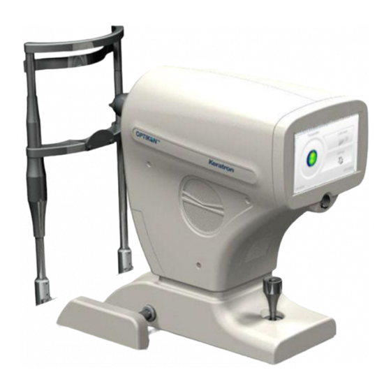
(axial powers, curvatures, and corneal aberrometry) and to provide information on the optical aberrations of the ocular or total wave front. The main identifiable elements in the Keratron™ are shown in Figure 5-1. They are: Power switch 7” LCD display with touch-screen: ... -
Page 16: Topography In The Keratron
(211 and 212 in Figure 5-2:) infra-red. In this way the mires reflected on the Keratron cornea (Figure 5-2: bottom left) are the same as the other Keratrons (28, at a uniform rate for the arc-step algorithm) without any compression in the centre. - Page 17 Topography Figure 5-2 : retro-mire working principle To establish when the eye is at the ideal distance from the cone, the Keratron™ Onda uses an advanced version of the EPCS (Eye Position Control System) electronic circuit adopted in the other topographs produced by Optikon 2000 S.p.A.
-
Page 18: Main Characteristics
For the processing and display and for the printing or filing of the examinations communication will be made with a generic external PC (not included), on which the Keratron "Scout" software is installed, via an Ethernet cable or via a wireless Wi-Fi connection. -
Page 19: Technical Specifications
Keratron™ Installation and operating manual OPTIKON 2000 5.2 TECHNICAL SPECIFICATIONS PARAMETER SPECIFICATIONS Manufacturer: ......OPTIKON 2000 S.p.A. Via del Casale di Settebagni, 13 00138 Rome - Italy Model: ......... Keratron™ Reference: ........161501 Regulatory conformity: ....Directive on medical devices 93/42/EEC Technical standards: .... - Page 20 Keratron™ Installation and operating manual OPTIKON 2000 Simulated K-Readings: ....Within ± 0.25D on a normal cornea. Distance error ......BFS deviation: with Slit Lamp Adapter typical within ........... ±0.15D Misalignement......Mean deviation on the map: ± 0.1 with misalignement ...........
-
Page 21: Electromagnetic Compatibility Tables
5.3 ELECTROMAGNETIC COMPATIBILITY TABLES 5.3.1 GUIDANCE AND MANUFACTURER'S DECLARATION – ELECTROMAGNETIC EMISSIONS Il Keratron™ intended for use in the electromagnetic environment specified below. The ™ customer or user of the Keratron should assure that it is used in such an environment. - Page 22 5.3.2 GUIDANCE AND MANUFACTURER'S DECLARATION – ELECTROMAGNETIC IMMUNITY The Keratron™ unit intended for use in the electromagnetic environment specified below. The customer or user of the Keratron™ should assure that it is used in such an environment. Electromagnetic Environment – Guidance...
- Page 23 RF transmitters, an electromagnetic site survey should be considered. If the measured field strength in the location in which the Keratron™ If the measured field strength in the location in which the Keratron™ should be observed to verify normal operation. If abnormal performance is observed, additional measures may be necessary, such as re- orienting or relocating the Keratron™.
- Page 24 The Keratron is intended for use in an electromagnetic environment in which radiated RF disturbances are controlled. The customer or user of Keratron™ can help preventing electromagnetic interference by maintaining a minimum distance between portable and mobile RF communications equipment (transmitters) and Keratron™ as recommended below, according to the maximum output power of the communications equipment.
-
Page 25: Light Emission
™ The Keratron contains various light sources. According to standard IEC 60825-1:1993 + A1:1997 + A2:2001 the Keratron™ is a Class 1 LED unit. Under any operating condition the maximum power emitted is less than the values indicated in the table below:... -
Page 26: Composition
Both the Keratron software in the unit and the Keratron Scout software in the PC communicating with the unit are products of Optikon 2000 S.p.A. For questions regarding updates and reporting errors or corrections, please contact: Optikon 2000 S.p.A. Via del Casale di Settebagni, 13 00138 Rome 2014-04-23 Rev.0... -
Page 27: Not Supplied Accessories
“Cleaning and disinfection”) NOTE: The Keratron™ system can function in conjunction with a PC and relative peripherals. The PC system (including the monitor and any additional peripherals) to be connected to the device must be in compliance with Standard EN 60601-1. - Page 28 OPTIKON 2000 TRADEMARKS: Windows 2000, Windows XP, Windows Vista Windows 7 and Windows 8 are registered trademarks of Microsoft Corporation Access is a registered trademark of Microsoft Corporation Keratron™ is a registered trademark of Optikon 2000 S.p.A 2014-04-23 Rev.0 Cod. 161501EN...
- Page 29 Keratron™ Installation and operating manual OPTIKON 2000 THIS PAGE IS INTENTIONALLY BLANK 2014-04-23 Rev.0 Cod. 161501EN 5-15...
-
Page 30: Installation
When cutting the packing material, be careful not to damage the contents. If the package or contents are damaged, notify the carrier (post office, railway or shipping agent) and Optikon 2000 as soon as possible. Check that the contents correspond to those indicated on the attached shipping documents. -
Page 31: Installation Procedure
OPTIKON 2000 6.3 INSTALLATION PROCEDURE After the Keratron™ has been placed on the support surface and the wheel protection covers have been placed in their position, the connections are to be made to the power supply and, if necessary, to a personal computer. - Page 32 Keratron™ can be implemented as additional ter minal (client) using a standard LAN or Wi-Fi cable (see §9.5). When the Keratron™ and a PC or network are con nected by means of a LAN cable, it is good practice to use a network, PC, monitor and related accessories...
- Page 33 Keratron™ Installation and operating manual OPTIKON 2000 THIS PAGE IS INTENTIONALLY BLANK 2014-04-23 Rev.0 Cod. 161501EN...
-
Page 34: Using The Keratron™ Home Screen
OPTIKON 2000 USING THE KERATRON™ HOME SCREEN The Keratron™ is turned on by placing the power switch (1 in Figure 5-1) in the “I” position. After a few seconds the user will see the screen shown below in Figure 7-1 ™... -
Page 35: Topography Calibration [Calibration]
7-4. Pressing the [OK] button causes the machine to perform an initial reading of the photoelectric cells that are free of obstacles. If the operator presses the [Abort] key, the Keratron™ returns to the initial screen, exiting calibration. 2014-04-23 Rev.0... - Page 36 Keratron™ Installation and operating manual OPTIKON 2000 Figure 7-4: Request for positioning the calibration target in front of the cone If the space between the photoelectric cells is not free, but is instead occupied by the calibration sphere, for example, the software could report the improper action by means of the message shown in Figure 7-5.
- Page 37 Keratron™ Installation and operating manual OPTIKON 2000 Figure 7-6: Transcription of the calibration sphere diopter power If the operator presses the [Start] key, the calibration proceeds through 6 steps: the first 3 are the acquisition of the calibration sphere by means of the pair of “Near”...
- Page 38 Keratron™ Installation and operating manual OPTIKON 2000 After you have acquired the image, only for the first of the six steps, the operator is requested to confirm whether the acquired sphere appears clean and free of dust grains (refer to Figure 7-8).
-
Page 39: Settings
OK position with the button already pushed down. IMPORTANT: ™ It is good practice to repeat the calibration daily when you turn on the Keratron However, it is indispensable to perform the calibration after the instrument has been installed or any time it is moved or cleaned. - Page 40 Keratron™ Installation and operating manual OPTIKON 2000 Figure 7-11: Information on the About folder After making any changes, the options can be confirmed by pressing the [OK] button or they can be cancelled by pressing [Abort] , which will return you to the initial screen (Figure 7-1).
- Page 41 If case of doubt on the changes applied, it is advisable to reset the factory values by pressing [Factory default]. In section Localization (Figure 7-14) you can set the language of the Keratron™ software by choosing one of the available languages.
-
Page 42: Corneal Topography [Topography]
Keratron™ Installation and operating manual OPTIKON 2000 Figure 7-14: Selection of the language in the Localization folder NOTE: In this manual, controls and messages are shown in English, which is the default language. The position and meaning of the messages and controls is the same in all languages. - Page 43 Keratron™ Installation and operating manual OPTIKON 2000 NOTE: To stop it, you simply need to press [Abort] in the upper left-hand corner. The screen in Figure 7-16 shows the live image of the patient’s eye (1). In the lower left-hand corner of the image (2), a position sensor detects and indicates whether you are acquiring the right or left eye.
- Page 44 NOTE: ™ Be careful not to hit the patient with the cone when moving the Keratron forward. To this end, instead of sitting behind the display, it is advisable to constantly observe from above the position of the cone with respect to the eye.
- Page 45 Keratron™ Installation and operating manual OPTIKON 2000 Figure 7-17: Reconstruction of the rings on an acquired image After acquiring the image, it is possible to send it to the external PC by pressing [Accept] (6) even without having processed it. This same action can be taken by pressing the button on the joystick.
- Page 46 Installation and operating manual OPTIKON 2000 Figure 7-19: The external PC is not present In both cases the Keratron asks the operator if the image should be discarded or memorized locally for subsequent transfer. The maximum number of images memorizable locally is 8.
- Page 47 Keratron™ Installation and operating manual OPTIKON 2000 On the right side of the screen are listed the values of power or curvature in diopters (Power), the distance from the centre in mm (Distance), the curvature radius in mm (Radius), the meridian (Meridian) and the height (Height) of the point shown by the pointer that can be easily placed on the curvature map.
- Page 48 Keratron™ Installation and operating manual OPTIKON 2000 THIS PAGE IS INTENTIONALLY BLANK 2014-04-23 Rev.0 Cod. 161501EN 7-15...
-
Page 49: Troubleshooting Guide
Installation and operating manual OPTIKON 2000 TROUBLESHOOTING GUIDE 8.1 TROUBLESHOOTING This section describes the messages that identify operating situations of the Keratron™ that have not been described previously in the manual. Symptom or Message Significance Action The unit is not correctly powered: Check the power cable. - Page 50 Keratron™ Installation and operating manual OPTIKON 2000 THIS PAGE IS INTENTIONALLY BLANK 2014-04-23 Rev.0 Cod. 161501EN...
-
Page 51: Software Keratron™ Scout On The External Pc
(65K or 16M colours). It is however recommended a screen size of at least 1024x768 pixels. ™ Do not alter any of the system files installed by the Keratron Scout Setup software, nor any file in the Database unless you have a specific competence on the PC and LAN management. -
Page 52: Download The Keratron™ Scout From The Web
Insert the CD-ROM into the reader; Wait a few seconds for the HTML page to load. Choose the “English” hyperlink; Choose the “Install Scout Rel xx.xx, for Keratron Scout & Keratron Bridge“ hyperlink; Choose “Run” when prompted... -
Page 53: Configuring The Direct Ethernet Connectionto The External Pc
See the troubleshooting section in this manual for the proper action. 9.4 CONFIGURING THE DIRECT ETHERNET CONNECTIONTO THE EXTERNAL PC To be able to communicate with the Keratron™ using the “crossed” Ethernet cable directly connected to the unit, it is necessary to correctly configure the network ™... - Page 54 Keratron™ Installation and operating manual OPTIKON 2000 Figure 9-1: Example of window "Network Connections" in Windows XP Figure 9-2 shows an example of a network connection. In the General folder at point 1 select “Internet Protocol (TCP/IP)” and press button Properties (2).
- Page 55 NOTE: The configuration shown in Figure 9-3 is compatible with the “Factory Default” ™ (factory settings) of Keratron The address must be selected following specific rules and not randomly. The configuration should be changed under the supervision of a network administrator.
- Page 56 Keratron™ Installation and operating manual OPTIKON 2000 Figure 9-4: Sharing and network connection center Figure 9-5 shows the connection status of the selected network. Figure 9-5: Connection status of the selected network Pressing the Properties button (1) allows you to access the protocols window (Figure 9-6).
- Page 57 Windows Vista/Windows 7 NOTE: The configuration shown in Figure 9-7 is compatible with the “Factory Default” (factory settings) of Keratron™. The address must be selected following specific rules and not randomly. The configuration should be changed under the supervision of a network administrator.
- Page 58 PC IP address, it will be necessary to enter the new address also in field Remote Host IP on the Keratron™. Network administrators can change the TCP/IP configuration of Keratron™ by selecting button “Local TCP/IP Settings” (2 in Figure 9-8).
-
Page 59: Configuration Of The Connection To The External Pc Using A
Figure 9-9. Figure 9-9: Selection of the DHCP mode If Keratron™ has a wireless connection, it is necessary to enter the network card you wish to use in the LAN card field. If DHCP has been configured for the Remote Host Computer, it is not possible to identify it using a static IP address. - Page 60 Installation and operating manual OPTIKON 2000 ™ Figure 9-10: In DHCP it is possible to specify the computer name used for the connection to Keratron 9.5.2 CONFIGURATION WITH STATIC ADDRESS Keraton™ Onda can be connected to a network using a static IP address following...
- Page 61 Keratron™ Installation and operating manual OPTIKON 2000 ™ Figure 9-11: Setting the IP address for Keratron Figure 9-12 shows an example of the subnet mask configuration. NOTE: The configuration parameters do not have default values. Therefore, it is advisable to set the required values for all parameters The existence of the network flow can be checked using field Status.
- Page 62 Keratron™ Installation and operating manual OPTIKON 2000 connection of Keratron™ to an existing local network. This field cannot be changed by the user. NOTE: It is always possible to reset the factory-set configuration by selecting “Factory Default” (3 in Figure 9-8).
-
Page 63: Keratron™ Scout Software Structure
OPTIKON 2000 9.6 KERATRON™ SCOUT SOFTWARE STRUCTURE Default database folder. Scout Trialsets folder (void after first installation). Keratron™ Scout system file. Pay attention to this folder! Put here imported print-templates, and those you create The SW puts here temporary files. *.tb Toolbar settings Scout.ini... -
Page 64: Customizing The Keratron™ Scout Software
By selecting Online Help (?) from the main menu and then selecting “Information on Scout”. By using Explorer to enter the folder c:\Keratron and using the right mouse button to select “Properties.” In the window that appears, select “Version”... -
Page 65: Uninstall Keratron™ Scout Software
Keratron™ Installation and operating manual OPTIKON 2000 Figure 9-14: Identification of the version of Scout 9.9 UNINSTALL KERATRON™ SCOUT SOFTWARE We can imagine two different methods: the first one uses the Windows standard uninstall procedure: Start “Control Panel” Click on “Add/Remove Programs” icon Select the “Keratron Scout“... -
Page 66: Description Of The Commands And Screens Of The Keratron™ Scout
(command or key “?” on the menu bar). 9.10.2 TRANSFERRING AN IMAGE FROM KERATRON™ In the acquisition menu, select “From Keratron Onda” or click the icon on the Scout software bar: “Acquire Onda images" and wait for Keratron™ to send the data. -
Page 67: Troubleshooting Keratron™ Scout Software
9.11 TROUBLESHOOTING KERATRON™ SCOUT SOFTWARE 9.11.1 KERATRON™ SCOUT SOFTWARE INSTALLATION ™ While the installation utility is copying Keratron Scout files in the PC hard disk, the following message could appear: THE FILE YOU ARE COPYING IS OLDER THAN THE FILE PRESENT IN THE PC ... -
Page 68: The File Scout.ini
Create a folder for each operator using the operating system function to navigate within the system (Explore Resources or Manage Resources) Create one database for each folder (using “Keratron Scout” function, “File” -> “New Database”). Every user will point to his database using “File->Open Database”, or from “File->Recent Database”... - Page 69 Reinstall the trial-sets. Restore the database(s) (from network, cd-rom…).. Restore the “Scout.ini” into the “C:\Keratron” fol der Restore the “C:\Keratron\*.tb” file (toolbar settings). NOTE: If you have installed some external programs, you have to re-enter the passwords.
-
Page 70: Miscellaneous Problems
The following guide lists some malfunctions which may occur, the symptoms and the ™ corrective actions. If the Keratron Scout system remains inoperative even after performing the corrective actions indicated below, contact Optikon 2000 S.p.A. sales/service department. SYMPTOMS CORRECTIVE ACTION Database a. - Page 71 Default settings do not correspond to the Exit the Scout program. last ones, or the database looks Cancel o change the name (for more “disappeared” security) to the file “C:\Keratron\Scout.ini”. Restart the Scout program and set the preferred options again. 2014-04-23 Rev.0 Cod. 161501EN...
-
Page 72: Updating Keratron.exe
Installation and operating manual OPTIKON 2000 9.12 UPDATING KERATRON.EXE To update the Keratron™ software you need to t ransfer it onto a USB flash drive from the Keratron™ Scout software. Insert the provided USB flash drive into the PC. Using the Keratron™ Scout software, it is possible to proceed with the manual updating by means of the command: Tools→... - Page 73 « OK », and wait for the operation to be completed and the software to launch. Then remove the USB flash drive. In any case, the Keratron™ keeps a copy of the previous software version. If you would like to restore it, you just need to insert the UBS flash drive and select «Restore previous version»...
-
Page 74: Cleaning, Sterilization And Maintenance
Before proceeding to clean any part of the instrument, place in the OFF (O) position the mains switch located on the rear panel of the Keratron™ and always disconnect the unit from the power outlet. -
Page 75: Cleaning The Accessories That Are Not Provided
§7.1. 10.3.1 REPLACING THE FUSE If after being turned on, the Keratron™ should remain inactive (the green LED on the Docking Base or the green light of the operating room cart’s switch is off), it is likely that the cause is a burned-out fuse;... -
Page 76: Replacing The Buffer Battery
The type of battery used is the CR 2032, and its voltage is 3V. NOTE: The used battery must be replaced by Optikon 2000 S.p.A. Technical Service or by personnel authorized by them. NOTE: In order to avoid loss of liquid if the instrument is not in use for a long period, contact Optikon 2000 S.p.A Technical Support or staff authorised by it, to have the battery... - Page 77 Keratron™ Installation and operating manual OPTIKON 2000 THIS PAGE IS INTENTIONALLY BLANK 2014-04-23 Rev.0 Cod. 161501EN 10-4...
-
Page 78: Index
Keratron™ Installation and operating manual OPTIKON 2000 INDEX Abort ........7-4; 7-7 ELECTRICAL SPECIFICATIONS ...5-5 Address ......... 9-10 EN 60601-1 ........3-3 anaesthetics ........3-2 entrance pupil ........5-4 anesthetics ........3-2 environment ........3-2 apex ....... 5-3; 5-4; 7-11 ENVIRONMENTAL SPECIFICATIONS artefacts .......... 3-2 .............5-5... - Page 79 ® Keratron Installation and operating manual OPTIKON 2000 Meridian ........7-14 Repeatability Check ......9-16 meridians ......... 5-4 Restore previous version ....9-23 mobile multiple power outlets ..3-3 Sim K ..........7-14 Offset ..........7-14 software version ......9-14 OK ........... 7-7 sources of heat ........3-2 Operator ........
-
Page 80: Appendix
® Keratron Installation and operating manual OPTIKON 2000 APPENDIX Eyelash artifacts Shadow projected Cone by eyelashes Detector This map shows a high-energy zone Artifact!! Caution The eyelashes’ shadow Eyelashes fool the detector crosses the horizontal line High-energy zone Cone Detector Ok !! The eyelashes’...
Need help?
Do you have a question about the KERATRON and is the answer not in the manual?
Questions and answers