
Subscribe to Our Youtube Channel
Summary of Contents for Mercury SmartCraft SC5000
- Page 1 SC5000 System View Version 3.XX Operation Manual 2003 Mercury Marine 90-892133 JULY 2003...
- Page 2 Sensors A to Z Preferences Favorites/Page Status Section 7 - Systems System Calibration Maintenance Log Active Alarms Alarm History Section 8 - Installation System View Installation Wiring Information Installation Configurations Section 9 - Index 2003 Mercury Marine 90-892133 JULY 2003...
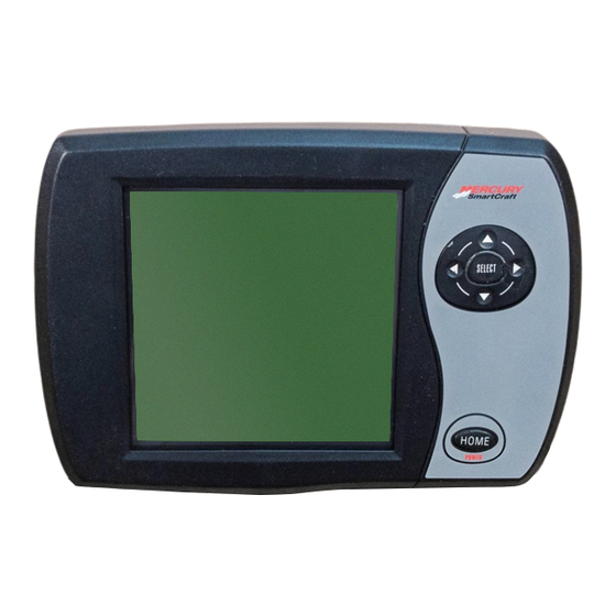
- Page 3 INTRODUCTION Introduction The SC5000 System View Display is a comprehensive boat information center. System View allows the boat operator to receive a wealth of critical operational information, dis- played clearly and instantly at the helm on the LCD display. The System View continuous- ly monitors and reports information ranging from basic operating data to detailed vessel environment information.
- Page 4 INTRODUCTION Keypad Usage The System View uses icons and text selection to perform all the functions. Arrow Trackpad Select Home The ARROW TRACKPAD controls up and down and side to side movement for on-screen function prompts. The SELECT key is used to select screen options and confirm data entry. The HOME (power) key has two different functions: 1.) Pressing the HOME key will return the System View display back to the home page directory.
- Page 5 INTRODUCTION Keypad Usage REMOTE LOCATION – ELECTRONIC THROTTLE AND SHIFT MODELS Console Remote Control – Dual Console Remote Control – Single Panel Remote Control Console Remote Control 1. Arrow Trackpad – Can be used to operate the up and down and side to side movement for System View on-screen function promps.
-
Page 6: Table Of Contents
GETTING STARTED GETTING STARTED Section 2 Table of Contents Starting up the System View ..........Display Screens . -
Page 7: Starting Up The System View
GETTING STARTED Starting Up the System View Turning on the main engine switch will start up the System View. The System View will move through a sequence of start-up screens shown below. Pressing SELECT will pause the screen. Display Screens Start-Up Screens The start-up screens can be set to display home page (Step 1) or the last display shown before power off (Step 2). -
Page 8: Home Page Screen
GETTING STARTED Display Screens Home Page Screen Across the bottom half of the home page you will find six on-screen main directory selec- tions. Use the trackpad to highlight the directory choice. Press SELECT to accept your choice and to open the directory screen. PROPULSION (See Section 3) NAV–FUEL (See Section 5) Direction to target waypoint information... - Page 9 GETTING STARTED Display Screens Home Page Screen (Continued) The top half of the home page displays engine data and vessel data. The engine data is received from sensors on the engine and the vessel data is received by vessel sensors. The initial screen layout takes one of two forms depending on whether one or two engines are installed.
-
Page 10: Data Display Screens
GETTING STARTED Display Screens Data Display Screens The data display screens can be selected from the main directory menu choices which are selected from the home page. The current directory menu selection icon is displayed in top-left of the display. The presentation of information on-screen will be shown in the information window located at the bottom on the screen. - Page 11 GETTING STARTED Display Screens Data Display Screens Glossary Data Screen Directory Location Engine Data Screen(s) Engine data screen(s) is a group of displays showing various engine data. Engine RPM and Speed Displays engine RPM and boat speed. Engine RPM Synchronizer Twin Engines –...
- Page 12 GETTING STARTED Display Screens Data Display Screens Glossary Data Screen Directory Location Steering Position Displays steering position in degrees. Tank Status Shows level of the vessel’s tanks. Tank Levels Displays the level of each tank. Vessel Status Displays engine run time Total fuel remaining Additional tank levels Air temperature...
- Page 13 GETTING STARTED Display Screens Data Display Screens Glossary Data Screen Directory Location Depth Plot Line Displays a plot line of depth vs. time as re- corded over the last 16 seconds. Environment Displays speed, depth, air temperature, and sea water temperature. Estimated Fuel Range Displays estimated range and fuel remaining, as well as current total fuel flow.
-
Page 14: Alarm Message Screens
GETTING STARTED Display Screens Alarm Message Screens When a problem is detected, the System View will alert the operator. Use the following steps to determine the cause of the problem: 1. A pop-up screen will appear displaying an alarm message. If there are multiple alarms, the display will show the last alarm activated. - Page 15 PROPULSION PROPULSION Section 3 Table of Contents Propulsion Information ............Entering the Propulsion Directory .
-
Page 16: Propulsion Information
PROPULSION Propulsion Information This Section will give a complete description of the display screens in the PROPULSION directory of the System View. Some of the propulsion functions are: Troll control Engine RPM combined with boat speed Twin engine synchronizer display Peak boat speed in conjunction with peak engine RPM Trim position Engine data screen(s) -
Page 17: Propulsion Data Screens
PROPULSION Propulsion Data Screens Engine RPM/Speed This screen displays engine speed (RPM) and boat speed. TWIN ENGINE SINGLE ENGINE Speed Sensors – This window shows the sensor that is currently sending the speed signal. The speed sensor is automatically selected based on what sen- sors are available. -
Page 18: Engine Rpm Synchronizer - Twin Engines
PROPULSION Propulsion Data Screens Engine RPM Synchronizer – Twin Engine This screen displays the difference in engine speed (RPM) between the port and starboard en- gines. Allows throttle adjustments to keep each engine running uniformly. Starboard Port Engine Engine Engine Data Screen(s) Engine data screen(s) is a group of displays showing various engine data. -
Page 19: Trim Position
PROPULSION Propulsion Data Screens Trim Position Display indicates the propulsion unit position achieved by setting trim and trailer position. SINGLE ENGINE TWIN ENGINE 90-892133 JULY 2003 Page 3-5... -
Page 20: Troll Control
PROPULSION Propulsion Data Screens Troll Control NOTE: Depending on your engine type, Troll Control feature may not be available. TWIN ENGINE SINGLE ENGINE BASIC OPERATION IMPORTANT: User must maintain constant helm control while using troll control to avoid obstacles. With troll control, you can maintain a trolling speed within a range specific to engine type without using the throttle. - Page 21 VESSEL VESSEL Section 4 Table of Contents Vessel Information ............Entering the Vessel Directory .
-
Page 22: Vessel Information
VESSEL Vessel Information This Section will give a complete description of the display screens in the VESSEL directory of the System View. Some of the vessel functions are: Steering angle position Tank status for fuel, oil, waste, and water Vessel status Entering the Vessel Directory To access the VESSEL directory, use the trackpad to highlight the VESSEL directory from the menu choice. -
Page 23: Vessel Data Screens
VESSEL Vessel Data Screens Steering Position This screen displays steering position in degrees. NOTE: Depending on your type of engine, this feature may not be available. NOTE: If steering angle position is opposite the direction that it should be, it can be reversed so it is displayed properly. -
Page 24: Fuel Tanks
VESSEL Vessel Data Screens Fuel Tanks Displays the level of each tank. Water and Waste Tanks Displays the level of each tank. Page 4-4 90-892133 JULY 2003... -
Page 25: Vessel Status
VESSEL Vessel Data Screens Vessel Status Displays the current vessel information. 1. Displays run time in hours. 2. Displays the total fuel remaining. 3. Displays additional tank levels. Fresh water and waste water if connected. 4. Displays air temperature at sensor. 90-892133 JULY 2003 Page 4-5... - Page 26 NAVIGATION/FUEL NAVIGATION/FUEL Section 5 Table of Contents Navigation/Fuel Information ..........Entering the Navigation/Fuel Directory .
-
Page 27: Navigation/Fuel Information
NAVIGATION/FUEL Navigation/Fuel Information This Section will give a complete description of the display screens in the NAV–FUEL direc- tory of the System View. Some of the navigation/fuel functions are: Navigation screens Next waypoint data Trip history log Depth Depth plot line Depth, speed, air temperature, and water temperature Seawater plot line Estimated fuel range... -
Page 28: Navigation/Fuel Data Screens
NAVIGATION/FUEL Navigation/Fuel Data Screens Navigation Screens IMPORTANT: This device is intended as a navigation aid and should not take the place of paper charts. A careful navigator never relies on one method to obtain posi- tion information. NOTE: For use of the navigation screens, your vessel must include a GPS receiver with NMEA 0183 V1.5 or V2.0+ output and be connected to the System View. -
Page 29: Next Waypoint Data
NAVIGATION/FUEL Navigation/Fuel Data Screens Navigation Screens SCREEN # 2 – NEXT WAYPOINT DATA When navigating to a waypoint, this screen will give you the following navigation informa- tion: 1. DIST TO GO – Remaining distance to the next waypoint. 2. TIME TO GO – Is the time that it will take to reach your waypoint at your present speed. 3. -
Page 30: Depth
NAVIGATION/FUEL Navigation/Fuel Data Screens Depth DEPTH displays the depth of water. NOTE: To set depth and shallow water alarm levels, refer to “Settings/Sensors” Menu in Section 6. Depth Plot Line DEPTH PLOT displays a plot of depth vs. time as recorded over the last 16 seconds. NOTE: To set depth and shallow water alarm levels, refer to “Settings/Sensors”... -
Page 31: Seawater Temperature Plot
NAVIGATION/FUEL Navigation/Fuel Data Screens Environment This screen displays speed, depth, air, and sea water temperature. 1. Displays depth of water. 2. Displays speed of the boat. 3. Displays the air temperature. 4. Displays the sea water temperature. Seawater Temperature Plot SEAWATER TEMP PLOT displays a plot of seawater temperature vs. -
Page 32: Estimated Fuel Range
NAVIGATION/FUEL Navigation/Fuel Data Screens Estimated Fuel Range ESTIMATED FUEL RANGE displays estimated range and fuel remaining, as well as current fuel flow. 1. The estimated fuel range is based on boat speed, fuel consumption, and fuel remaining in the tank. The number displayed indicates an estimate of the distance you can travel on the remaining fuel. - Page 33 SETTINGS SETTINGS Section 6 Table of Contents Settings Information ............Entering the Settings Directory .
-
Page 34: Settings Information
SETTINGS Settings Information This Section will give a complete description of the Settings screens in the SETTINGS direc- tory of the System View. In this Section you can configure your System View to display the information the way you prefer. Some of the Settings functions are: Customizing the home page data Contrast/Lighting/Clock... -
Page 35: Settings Options
SETTINGS Settings Options Contrast/Lighting/Clock To adjust a setting: 1. Press YB to highlight the desired menu selection. 2. Press A" to edit the menu box. 3. Press SELECT to accept settings. CONTRAST – Provides a slide bar to adjust the display screen contrast to compensate for changes in temperature or lighting conditions. -
Page 36: Units/Language/Offsets
SETTINGS Settings Options Units/Language/Offsets To adjust a setting: 1. Press YB to highlight the desired menu selection. 2. Press A" to edit the menu box. 3. Press SELECT to accept settings. UNITS ENG – Lets you select English or metric format for unit measurements. UNITS SPD –... -
Page 37: Home Page Data
SETTINGS Settings Options Home Page Data 4. Look at the HOME PAGE DATA and determine if there is any data that you would like to change. Press YB to select function. Press A" to edit the function. VOLTS SPEED H20 PSI H20 PSI DEPTH Oil PSI... - Page 38 PADDLE FREQ – Frequency can be changed to match requirements of different sensors. 4.9 Hz per mile or 5.7 Hz per knot is the frequency of the paddle wheel speed sensor provided by Mercury Marine. TRANSITION SPD – Transition speed is the boat speed at which System View stops looking at the paddle wheel and starts using the pitot or GPS (GPS is priority for high speed if connected) to mea- sure boat speed.
- Page 39 SETTINGS Settings Options Preferences To adjust a setting: 1. Press YB to highlight the desired menu selection. 2. Press A" to edit the menu box. 3. Press SELECT to accept settings. WARNING HORN – The System View has a warning horn alarm. You can set an alarm to sound a warning tone for various fault alarms and shallow or deep water depth warning.
- Page 40 SETTINGS Settings Options Favorites/Page Status The favorites/page status allows you to select one of the two following options: 1. Allows you to choose your preferences screens and place them into the FAVORITES directory for quick viewing. Screens will still be shown in their respective menus. 2.
- Page 41 SYSTEM SYSTEM Section 7 Table of Contents System Information ............Entering the System Directory .
-
Page 42: System Information
SYSTEM System Information This Section will give a complete description of the screen settings in the SYSTEM directory of the System View. Some of the system functions are: Maintenance log Active alarms Alarm history System calibration Entering the System Directory To access the SYSTEM directory, use the trackpad to highlight the SYSTEM directory from the menu choice. -
Page 43: System Calibration
SYSTEM System Calibration System Calibration The system calibration consists of the following menus: Tank configuration Trim calibration Factory defaults User keyless code Entering into System Calibration IMPORTANT: Entering into the system calibration menus will require you to shut down the engine(s) in order to reactivate the System View. 90-892133 JULY 2003 Page 7-3... -
Page 44: Tank Configuration
SYSTEM System Calibration Tank Configuration NOTE: System View allows you to choose the name of the tanks you want to appear on the screen. You can choose two tanks per engine. 1. Choose the names of the tank(s), that you would like to appear on screen. highlight the tank you would like to change. - Page 45 SYSTEM System Calibration Tank Configuration (Continued) NOTE: The fuel tank will have to be calibrated in order for System View to display fuel range. 3. There are two methods for calibrating fuel tank level: a. Method 1 – Select DEFAULT – The System View will automatically supply an esti- mated range value based on default sensor values.
-
Page 46: Trim Calibration
SYSTEM System Calibration Trim Calibration CALIBRATING THE TRIM SENSOR To calibrate trim: 1. Open the TRIM CALIBRATION menu. 2. TRIM ENG DOWN: Press the SELECT key to open the DOWN screen. Trim the engine all the way down. Press SELECT to save and move to next screen. 3. -
Page 47: Factory Defaults
SYSTEM System Calibration Factory Defaults RESET SETTINGS DIRECTORY Restores all settings back to System View’s original setup values. To restore settings back to original setup values: 1. Open FACTORY DEFAULTS menu. 2. Press YB to highlight RESET SETTINGS DIRECTORY selection. 3. -
Page 48: User Keyless Code
SYSTEM System Calibration User Keyless Code A keyless code can be set to prevent unintentional power-up of the System View when using the HOME (Power) button. Once a keyless code has been set, the System View will require the code number to be entered when powering-up the System View using the HOME (Pow- er) button. - Page 49 SYSTEM System Calibration User Keyless Code CHANGING YOUR KEYLESS CODE NUMBER 1. Power up the System View using the HOME button. 2. Open the System View directories to access the USER KEYLESS CODE menu. 3. Enter your existing 4 digit key code number in the first menu box as follows: a.
-
Page 50: Maintenance Log
SYSTEM Maintenance Log Maintenance Log RECORDING RUN TIME The maintenance log allows you to record the current engine run time at each service inter- val. Service intervals should be performed at the time periods specified in your Engine Op- eration, Maintenance Manual. Recording engine run time at maintenance intervals: 1. -
Page 51: Active Alarms
SYSTEM Active Alarms Active Alarms The ACTIVE ALARMS screen displays all active alarms. The active alarm message will alert the operator to the potential problem. When a problem is detected with the system, the System View will alert the operator to the potential problem by displaying the alarm data in the information window, located at the bot- tom of the view screen. - Page 52 SYSTEM Active Alarms Helm Active Alarms Alarm Message Active Alarm Description (Pop-Up Screen) PORT HEAD OVRHT The engine has overheated. Refer to the STBD HEAD OVRHT Engine Operation and Maintenance Manu- COMPRESS OVRHT al for information on overheating. BATTERY VOLT HI Battery voltage is above the allowable lim- it.
- Page 53 SYSTEM Active Alarms Helm Active Alarms Alarm Message Active Alarm Description (Pop-Up Screen) PITOT CKT HI/LO Pitot sensor circuit problem. Have the sys- tem checked by your dealer. PRT COOL OVRHT The engine has overheated. Refer to the Engine Operation and Maintenance Manu- al for information on overheating.
- Page 54 SYSTEM Active Alarms Helm Active Alarms Alarm Message Active Alarm Description (Pop-Up Screen) ECT OVRHT Water temperature in engine is too hot. Cooling problem. Have the engine checked by your dealer. GUARDIAN Guardian is trying to protect the engine by reducing engine speed.
-
Page 55: Alarm History
SYSTEM Alarm History Alarm History The ALARM HISTORY displays all alarms that are, or have been active since last engine key-up. To view alarm history: 1. Open the ALARM HISTORY directory. The directory will display alarm history. 90-892133 JULY 2003 Page 7-15... - Page 56 INSTALLATION INSTALLATION Section 8 Table of Contents Components ............. . . Special Information .
-
Page 57: Components
INSTALLATION SYSTEM VIEW INSTALLATION Components : REF. QTY. DESCRIPTION PART NUMBER Cover 879948T04 Bezel 879947T03 System View with seal 79-888923K05 Seal Screw 10-66687 Flat washer 12-56681 Wing nut 11-816874 Mounting adaptor 859021 Washer 12-859029 11-859022 Temperature sensor 885342001 SmartCraft harness 84-882755T02 Special Instructions Clean lens with water only. - Page 58 INSTALLATION System View Installation 1. Select a location for the System View that affords good visibility and accessibility from behind dashboard. 2. Cut out mounting hole to the given dimensions. 3. Place System View along with seal into dashboard and secure with 4 screws. Screw (4) Flat washer (4) Wing nut (4)
-
Page 59: Wiring
INSTALLATION Wiring MODELS WITHOUT ELECTRONIC THROTTLE/SHIFT NOTE: Extension Wiring Harnesses for the System Link gauges are available in 3 ft, 10 ft and 30 ft lengths. (84-880756b-3,10,30) – System view Display harness System link gauge connection – (starboard) System link gauge connection – (port) GPS (Optional) connection Horn –... - Page 60 INSTALLATION Wiring ELECTRONIC THROTTLE/SHIFT MODELS – SINGLE ENGINE NOTE: Extension Wiring Harnesses for the System Link gauges are available in 3 ft, 10 ft and 30 ft lengths. (84-880756b-3,10,30) – System view DTS Command Module harness System link gauge connection – (starboard) System link gauge connection –...
- Page 61 INSTALLATION Wiring ELECTRONIC THROTTLE/SHIFT MODELS – TWIN ENGINES NOTE: Extension Wiring Harnesses for the System Link gauges are available in 3 ft, 10 ft and 30 ft lengths. (84-880756b-3,10,30) – System view Display harness System link gauge connection – (starboard) System link gauge connection –...
-
Page 62: Connecting Optional Gps Unit To The System View
INSTALLATION Connecting Optional GPS Unit to the System View NOTE: The GPS unit must comply to the National Marine Electronic Association NMEA 0183 Interface Standard v1.5, v2.0 or later compatible version. First, look at the GPS wiring diagram and determine what two leads are the GPS output leads. - Page 63 INDEX INDEX Section 9 Alarms– Active ....7-11 Home Page Data ....Air Temperature .
- Page 64 INDEX Start–up Page Preference ..Start–up Screens ....Starting Up the System View ..Steering Offset .
Need help?
Do you have a question about the SmartCraft SC5000 and is the answer not in the manual?
Questions and answers