
Related Manuals for LEGRAND Raritan MCD Series


Summary of Contents for LEGRAND Raritan MCD Series
- Page 1 MasterConsole Digital (MCD and MCD- LED17 Series) Release 2.3.0 Copyright © 2022 Raritan MCD-0G-v2.3.0-E August 2022 Release 2.3.0...
-
Page 2: Table Of Contents
Contents Introduction to MasterConsole Digital Series Products Product Photos................6 Before Installation. - Page 3 Using the On-Screen Display Interface OSD Layout................31 Login Screen.
- Page 4 Upgrade Procedure Overview............. . 62 Step 1: Download the Latest Firmware and Upgrade Utility.
- Page 5 Power Safety Guidelines To avoid potentially fatal shock hazard and possible damage to Raritan equipment: • • Do not use a 2-wire power cord in any product configuration. • • Test AC outlets at your computer and monitor for proper polarity and grounding. •...
-
Page 6: Introduction To Masterconsole Digital Series Products
Introduction to MasterConsole Digital Series Products There are two types of MasterConsole Digital (MCD) KVM product models, which are functionally similar. • • MCD KVM switches • • MCD‑LED KVM combination switch and KVM drawer The major difference between the two products is MCD is a normal KVM switch without a built-in keyboard, mouse and display, and MCD‑LED is a KVM switch with a built-in keyboard, touchpad and LCD display. - Page 7 ▶ MDCIM-DVI ▶ MDCIM-HDMI...
- Page 8 ▶ MDCIM-DP ▶ MDUTP cables...
-
Page 9: Before Installation
Before Installation • • It is very important to locate this product in a suitable environment. • • The surface for placing and fixing this product should be stable and level or mounted into a suitable cabinet. • • Make sure the place has good ventilation, is out of direct sunlight, away from sources of excessive dust, dirt, heat, water, moisture, and vibration. -
Page 10: Masterconsole Digital Kvm Switches
MasterConsole Digital KVM Switches A MasterConsole Digital (MCD) switch is a KVM (keyboard/video/mouse) switch that enables you to control multiple servers from a single set of keyboard, mouse, and monitor. There are four MCD models, which support different numbers of users and servers. •... -
Page 11: Dual-User Models
MCD‑108 has 8 channel ports, and MCD‑116 has 16. Dual-User Models The dual-user model allows up to "two" users to access connected servers at a time. These models include MCD‑216 and MCD‑232. MCD‑216 has 16 channel ports, and MCD‑232 has 32. You can use C5R-DVI-HD at the local port to extend the length of keyboard, mouse and video connections. -
Page 12: Mcd Package Contents
• Standard USB keyboards and mice • • DVI, HDMI, Display Port and VGA • • Analog audio (MDUTP cables) • • Digital audio (MDCIM-HDMI) • • • Support the video resolution up to 1920 x 1200 @60Hz (analog) or 1920x1080@60Hz (digital) •... -
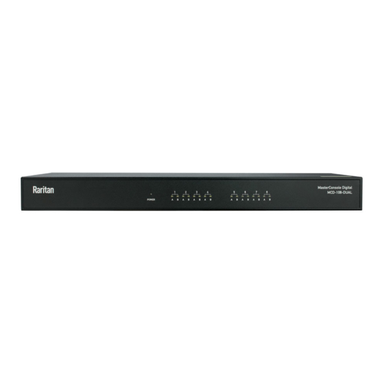
Page 13: Front View
Front View 1 Power LED Turn on after powering on the MCD switch. 2 Channel LEDs • • Turn off for "inactive" channels. • • Turn on for "active" channels. The color is white, and will turn green when any channel is being accessed. -
Page 14: Mcd Computer Interface Modules
One DVI-I connector Connect a monitor. • • If your monitor does not have a DVI connector, an appropriate video converter or adapter is required. 3 'Console 1' connectors Connect the data input/output devices. • • 'Console 1' is available on all MCD models. a, b, c Refer to a, b, and c shown above. -
Page 15: Mcd Rackmount Procedure
Model Cable length MDUTP20-VGA 2 meters (6.5 feet) MDUTP40-VGA 4 meters (13 feet) MDUTP60-VGA 6 meters (20 feet) MDUTP150-VGA 15 meters (49 feet) Important: If the audio functionality is wanted, make sure you turn on the audio feature on your MCD switch in addition to using the audio-capable MDCIM-HDMI or MDUTP cable. -
Page 16: Step 2: Rack Mount The Mcd
Step 2: Rack Mount the MCD When rack-mounting the MCD switch, you can let it face either the front or the rear of the rack to meet your needs. ▶ To rack-mount the MCD: 1. Slide the MCD switch between the two rackmount brackets. 2. -
Page 17: Masterconsole Digital-Led Kvm Drawer
MasterConsole Digital-LED KVM Drawer MasterConsole Digital-LED (MCD‑LED) series is a KVM drawer which is functionally similar to MCD KVM switches. For information on MCD KVM switches, see MasterConsole Digital KVM Switches (on page 10). Important: MCD‑LED KVM drawers do NOT support audio transmission even though an audio-capable MDCIM or MDUTP cable is used. -
Page 18: Mcd-Led Product Features
MCD-LED Product Features • • MCD‑LED KVM drawers come with a 17" LED LCD display, built-in keyboard and touchpad • • A user can control multiple servers per unit. • • The number of servers is model dependent. • MCD‑LED17108 supports a maximum of 8 servers •... -
Page 19: Mcd-Led Structure Diagrams
MCD-LED Structure Diagrams This section provides a brief introduction to the components on the front and rear sides of the MCD- LED switch. The following diagrams illustrate MCD‑LED17116. Front View 1 Touchpad and keyboard Operate the MCD‑LED KVM drawer 2 USB port •... -
Page 20: Rear View
6 OSD buttons, power OSD buttons: Display and operate the OSD menu, which adjusts the video or OSD button and indicator lamp settings of the built-in LCD display. For detailed information, see MCD-LED Display's OSD Menu (on page 56). Note: This OSD menu is different from the OSD for channel selection and system settings, which is described in the chapter titled Using the On- Screen Display Interface... -
Page 21: Mcd-Led Rackmount Procedure
▶ MDCIMs: • • MCD Computer Interface Modules (on page 14). ▶ MDUTP cables: • • MDUTP Cables (on page 14). MCD-LED Rackmount Procedure MCD‑LED KVM drawers can be mounted in 1U (1.75", 4.4cm) of vertical space in a standard 19" equipment rack. -
Page 23: Quick Start
Quick Start This section provides instructions on setting up a basic MCD or MCD-LED KVM system and accessing connected servers. For instructions on rack-mounting each product, see MCD Rackmount Procedure (on page 15) or MCD- LED Rackmount Procedure (on page 21). ▶... -
Page 24: Step B: Connect The Keyboard/Mouse/Monitor
MCD CIM type Video type Audio transmission MDUTP cables Support analog audio MDCIM‑DVI NO support MDCIM‑HDMI HDMI Support digital audio MDCIM‑DP Display Port NO support Tip: If the MDCIM or MDUTP cable you purchase is not compatible with the video port on your server, the alternative solution is to connect a video converter or adapter to MDCIM or MDUTP. - Page 25 • Optionally, plug the MDUTP cable's audio connector into the server's audio output port. • 2. Connect the server to the MCD switch. The distance can be up to 45 meters (147.6 feet). • MDCIM: Use a standard network patch cable (Cat5e/6 UTP) to connect the MDCIM attached with •...
-
Page 26: Using The Mcd-Led
Using the MCD-LED 1. Pull out the MCD‑LED. 2. Push the locking latches toward the center. 3. Flip up the LCD display, and press the power button on the LCD display. 4. To fine tune the video quality after accessing a server, do either below: •... -
Page 27: Initial Osd Operation
Initial OSD Operation MCD and MCD‑LED share the same OSD operations. Login After turning on the device, the login screen displays. For initial login, use the built-in administrator account. ▶ To log in: 1. Type the default user credentials and press Enter. User credentials are case sensitive. •... -
Page 28: Accessing A Server
Important: It is strongly recommended to change the default password for the security of your MCD system. For details, refer to "User Management (on page 36)" in the User Guide. Accessing a Server After login, you can select any channel to view and/or control the connected server. There are two methods for channel selection. - Page 29 2. If the desired channel is not shown on the current page, press Page Down or Page Up. 3. Press to select one of the "active" channels, and press Enter. • Channels with channel names displayed are "active" channels. The default name is 'PC'. See •...
-
Page 30: Logout
▶ To access the next or prior "active" channel, using hot keys: 1. Make sure there is no OSD shown onscreen. 2. To select the next "active" channel, press the RIGHT 'Ctrl' key twice. 3. To select the prior "active" channel, press the LEFT 'Ctrl' key twice. Logout After completing your tasks, you should log out to prevent unauthorized people from accessing the MCD KVM system. -
Page 31: Using The On-Screen Display Interface
Using the On-Screen Display Interface In this chapter, the name 'MCD' refers to both MCD switches and MCD‑LED KVM drawers unless otherwise specified. The On-Screen Display (OSD) interface offers these functions: • • Channel selection • • System configuration • •... -
Page 32: Login Screen
Login Screen Device ID The model name of your MCD switch. User Port The ID number of your console. • • 01 refers to Console 1. • • 02 refers to Console 2, which is only available on dual-user models. User Name, The fields for entering user credentials. - Page 33 Model name Your MCD switch's model name. Selected channel The number of the channel that is being accessed. Channel numbers 8 channel numbers of current page. Channel names Available channel names of current page. • • Per default an active channel's name is 'PC'. You must customize the channel names. Specifying Channel Names (on page 35).
-
Page 34: Channel Id
Base switch's model Your 1st‑tier MCD switch's model name. name 1st‑tier channel The number of the 1st-tier channel where the 2nd‑tier MCD switch is connected. Selected 2nd‑tier The number of the 2nd‑tier channel that is being accessed. channel 2nd-tier channel 2nd-tier channel names. -
Page 35: Specifying Channel Names
Channel number which is being selected Channel name of the selected channel ▶ 2nd-tier channel ID: On a two‑tier system, if you select the channel of a 2nd‑tier switch, its channel ID looks like the following. 1st‑tier channel number where the 2nd‑tier switch is connected 2nd‑tier channel number which is currently selected Channel name of the selected 2nd-tier channel Specifying Channel Names... -
Page 36: User Management
▶ To change channel names: 1. If the OSD is not displayed, press the hot key 3 times. • The default hot key is 'Scroll Lock.' To change it, see • System Settings (on page 41). 2. On the Selection Menu, select an active channel and press F3. •... - Page 37 3. On the SETUP page, press F5. The User Configuration page displays. 4. Press to select the desired user. • Press Page Up or Page Down if the desired user is not shown on the current page. • 5. Press Enter, and that user's password change page displays. Then follow either procedure below. 6.
- Page 38 ▶ To change the administrator's password: Important: It is strongly recommended to change the admin password. Then note it down and keep it in a secure place. If you forget the password, contact the local dealer or Lenovo for RMA service. 1.
-
Page 39: Setting User Port Access Privileges
Important: It is recommended to note down all user names and passwords, and keep the data in a secure location. Setting User Port Access Privileges You can set user privileges to access each port. ▶ To set user privileges to ports: 1. - Page 40 4. In User Config, choose the user and press “F1” for Security settings. 5. Port Access setup opens. • Press the UP and DOWN arrows to select the port. • • Press the LEFT and RIGHT arrow keys to change the port access authority in the Access column. •...
-
Page 41: System Settings
System Settings You can adjust the MCD KVM system settings, such as changing the hot key or scan rate. Only the administrator has the permission to change system settings. ▶ To change system settings: 1. Log in as the administrator -- that is, admin. For details, see Login (on page 27). -
Page 42: Available Settings And Options
Available Settings and Options This section describes the functions and options of each item on the SETUP page. See System Settings (on page 41). Field Options/values Function Oper Mode PC SHARE, or The operation mode determines whether two users of a "dual‑user" model (for dual- PRIVATE can access the same channel or not. -
Page 43: Adjusting The Osd Position
Field Options/values Function Buzzer ON or OFF Turn on or off the buzzer of the MCD switch. Audio ON or OFF Turn on or off the audio support. • • ON: Turn on the audio. This is the default. • •... -
Page 44: Channel Scan
• ID: • 5. Now move it to the position you prefer by pressing the arrow keys. 6. To confirm the new position, press Esc. Then the OSD returns to the SETUP page shown in step 2. 7. To exit the SETUP page, press Esc. Channel Scan You can turn on the Scan function to have the MCD switch automatically display the video of every channel one by one on the screen. -
Page 45: Video Adjustment
• 2nd‑tier channel ID comprising the word 'SCAN', 1st-tier channel number, 2nd-tier channel number • and 2nd-tier channel name ▶ To end the channel scan: 1. Press any key on the keyboard. 2. The channel ID's format returns back to normal, indicating the scan mode ends. For details on channel IDs, see Channel ID (on page 34). -
Page 46: Viewing Firmware Version
4. Press to select the video brightness or contrast. • • : Brightness • • : Contrast 5. Press to adjust the value after the cursor is located in the desired video property. 6. Press Esc to save the changes and exit. Viewing Firmware Version You can check the current versions of OSD and USB driver implemented on the MCD switch to determine whether it is necessary to update your MCD switch. -
Page 47: More Channel Information
3. Press Enter to proceed with the factory reset. The following message appears. • To cancel instead, press Esc. • 4. Wait until the Login screen re-appears, indicating the reset is completed. More Channel Information Active and inactive channels are determined with the power status of the connected MDCIM or MDUTP cable. -
Page 48: Releasing A Channel In The Pc Shard Mode
Color Channel status Green This is an active channel that you can access. • • In the Private mode, active channels are green as long as the other user is NOT accessing them. • • In the PC Share mode, every active channel is green no matter the other user is accessing it or not. - Page 49 ▶ To share access to servers: 1. Ensure that the PC Share mode is activated or applied. 2. Now you can share the same channel with the other user. Depending on the channel access sequence, you may or may not be able to control the server. •...
-
Page 50: Two-Tier System
Two-Tier System You can connect multiple MCD KVM switches to organize a two-tier system, expanding the number of available channels. Different MCD models can be mixed in the system. If the system completely comprises MCD‑232 models, the number of connected servers can be expanded to 1024. In This Chapter Overview. -
Page 51: Limitations Of The Two-Tier System
2nd-tier MCD switches MCD KVM switch (or MCD‑LED KVM drawer) as the base switch Keyboard, mouse, and monitor Limitations of the Two-Tier System The two-tier system has several limitations. • • There is only one path (Cat5e/6 UTP cable) between the base switch and each 2nd-tier switch. When a user from the base switch is accessing any channel of a 2nd-tier switch, there are no other paths left for the other user from the base switch to access the same 2nd-tier switch's channels. -
Page 52: Step (B): Connect Keyboards, Mice, Monitors And Audio Devices
3. Repeat the above step to connect more 2nd-tier switches to the base switch. 4. Turn on all "2nd-tier" switches. 5. Turn on the base switch. Important: Turn on 2nd-tier switches prior to the base switch so that the base switch downloads up-to-date channel data from the 2nd tier. - Page 53 Warning: If any 2nd‑tier switch is a dual‑user MCD model, DO NOT connect a keyboard, mouse and monitor to Console 2 because Console 2 is disabled.
-
Page 54: Step (C): Connect Servers
Step (c): Connect Servers You can connect servers to any channel ports in the two-tier system, including those on the base and second-tier switches. For details on server connections, see Basic Installation (on page 23). -
Page 55: Accessing Or Exiting 2Nd-Tier Channels
Accessing or Exiting 2nd-Tier Channels The only method to access the 2nd-tier channels is the OSD's Selection Menu. To return to the base switch's channels, you also have to operate the Selection Menu. ▶ To access the 2nd-tier channels: 1. If the OSD is not displayed, press the hot key 3 times. •... -
Page 56: Mcd-Led Display's Osd Menu
MCD-LED Display's OSD Menu You can customize the video properties of the LED display of a MCD‑LED KVM drawer by configuring the OSD menu for the LED LCD display. In the following context, the name 'LED OSD' refers to the OSD menu for the LED display, not the OSD for channel selection and system settings. -
Page 57: Onscreen Menu
Buttons Function POWER Power on/off the built-in LED display. The LED indicator lamp indicates the current power on/off status. • • Light off = LED display power off • • Light on = LED display power on UP/AUTO This button has two functions: •... -
Page 58: Auto Adjust
Auto Adjust • • Auto Adjust: Fine tune the video signals to eliminate waviness and distortion. An "Auto Adjusting" message is displayed during the process. Luminance • • Brightness: Make the screen image brighter or darker. • • Contrast: Adjust the difference between the background black level and foreground white level. •... -
Page 59: Management
Management • • H. Position: Move the screen image left or right. • • V. Position: Move the screen image up or down. • • Pixel Clock: Adjust the clock/pitch to synchronize the sampling clock of the LED display with the pixel clock of the connected equipment. -
Page 60: Osd
Add red to the screen image, making the white warmer. • • 5400: Add green to the screen image, making the white cooler. • • User Preset: Adjust red, green and blue colors respectively. • • H. Position: Adjust the horizontal position of the 'LED OSD'. •... -
Page 61: Recall
Recall • • Recall Color: Reset all colors to factory defaults. • • Recall All: Reset all settings to factory defaults except for the language setting. A confirmation message appears after selecting either Recall option. Press UP/AUTO to select Yes and then press MENU to confirm the operation. -
Page 62: Firmware Upgrade
Firmware Upgrade You can upgrade the firmware of the MCD switch, MCD‑LED KVM drawer, or MDCIM/MDUTP to benefit from the latest enhancements and features whenever new firmware is released on the Raritan website. Note that the firmware upgrade utilities and firmware files for the KVM switch and MDCIM/MDUTP are different. -
Page 63: Step 2: Connect The Desired Switch To The Computer Running The Upgrade Utility
▶ To download the firmware and upgrade utilities: 1. Visit the Raritan website (www.raritan.com). 2. Click Support on the top. 3. Choose the MasterConsole Digital (MCD) series product from the 'Choose a Product' list. 4. In this product's section, look for the desired firmware upgrade file and click it to start the download. -
Page 64: Step 3: Launch The Upgrade Utility For The Switch
Step 3: Launch the Upgrade Utility for the Switch The following procedure applies to MCD switches and MCD‑LED KVM drawers, but NOT to MDCIM/ MDUTP. To ensure the success of the upgrade, always use the latest upgrade utility downloaded along with the MCD firmware. - Page 65 2. Verify whether the utility detects the connected MCD switch. If yes, a green bullet and blue text as shown above is displayed on the top of the utility. • If not, the top-left bullet does not turn green, and the red text is displayed on the top instead. •...
- Page 66 7. When the upgrade completes, verify the upgrade result. If it is successful, a green bullet and blue text 'Program OK' is displayed on the top of the utility. • If the upgrade fails, the top-left bullet does not turn green, and red text is displayed on the top •...
-
Page 67: Step 2A: Launch The Upgrade Utility And Connect Mdcim/Mdutp
10. Press "Enter" to restore the device. Step 2A: Launch the Upgrade Utility and Connect MDCIM/MDUTP The following procedure applies to MDCIMs and MDUTP cables, but NOT to MCD switches and MCD‑LED KVM drawers. To ensure the success of the upgrade, always use the latest upgrade utility downloaded along with the MDCIM/MDUTP firmware. - Page 68 2. If the USB radio button is NOT selected yet in the 'Connection type' section, select it. A window similar to the following then appears. Simply close this window. 3. Perform all actions of this step within 5 seconds since the utility is launched. Otherwise, the utility may not be able to detect the connected MDCIM or MDUTP.
- Page 69 b. Click Connect in the firmware upgrade utility. Warning: If the sequence of step 3 is NOT followed or the button 'Connect' is NOT clicked within 5 seconds, the utility may fail to detect the connected MDCIM or MDUTP. If this issue occurs, close the utility, disconnect the MDCIM/MDUTP from the computer, and then repeat all of the above steps until the MDCIM/MDUTP is detected successfully.
- Page 70 5. Click APROM to select the appropriate MDCIM/MDUTP firmware file.
- Page 71 6. Click Start to start the firmware upgrade. 7. When the firmware upgrade is completed successfully, a green message 'PASS' is displayed at the bottom.
- Page 72 8. If there are more MDCIMs or MDUTP cables to upgrade, keep the utility open, remove the currently- connected MDCIM/MDUTP and reconnect a new one to the computer. Then repeat steps 6 to 8 until all MDCIMs and MDUTP cables are upgraded.
-
Page 73: Specifications
Appendix A Specifications In This Chapter One-User MCD Models..........73 Dual-User MCD Models. -
Page 74: Dual-User Mcd Models
Items MCD‑108 MCD‑116 Power consumption DC 12V/5.42A (65W) Operating temperature 0 to 50°C Storage temperature -20°C to 60°C Humidity 0-80% RH , Non-condensing Dimension (L x W x H) 440 x 150 x 44 mm Weight (g) 1963 1993 Safety CE/FCC/VCCI/UL MTBF >... -
Page 75: One-User Mcd-Led Models
Items MCD‑216 MCD‑232 Max. power input AC100-240V/1.5A, DC12V/5.42A Power consumption DC 12V/5.42A (65W) Operating temperature 0 to 50°C Storage temperature -20°C to 60°C Humidity 0-80% RH , Non-condensing Dimension (L x W x H) 440 x 150 x 44 mm Weight (g) 2009 2276... -
Page 76: Supported Vga And Dvi Resolutions Of Mcd
Items MCD‑LED17108 MCD‑LED17116 Video support 1920 x 1080 @60Hz DDC2B For details, see Supported Video Resolutions of MCD-LED (on page 77). Built-in LCD display 17.3" TFT LCD with LED backlight unit • • Pixel pitch: 0.1989 (H) x 0.1989 (V) mm •... -
Page 77: Supported Video Resolutions Of Mcd-Led
VGA resolutions (analog) DVI resolutions (digital) 1280 x 768 @60/75Hz 1280 x 800 @60/70/75Hz 1280 x 800 @60/75Hz 1280 x 960 @60/70/75Hz 1280 x 960 @60Hz 1280 x 1024 @60/70/75Hz 1280 x 1024 @60/75Hz 1360 x 768 @60Hz 1360 x 768 @60Hz 1440 x 900 @60Hz 1600 x 900 @60Hz 1680 x 1050 @60Hz... - Page 78 Available video resolutions 1600 x 1200 @60Hz 1680 x 1050 @60Hz 1920 x 1080 @60Hz Note:DVI monitors takes longer time to swap resolutions, so it is recommended to preset the resolutions. The delay is caused by video signals slow process due to swapping from digital to analog then back again to digital.
-
Page 79: Ground Screw
Appendix A Ground Screw If you want to prevent any electrical shock, you can use the ground screw on the rear panel to provide a safe electrical path to the ground. Note: Currently only MCD‑LED KVM drawers have the ground screw while MCD switches do NOT have ▶... -
Page 80: Integration With Other Raritan Products
Appendix A Integration with Other Raritan Products MCD switches can work with the following Raritan products. Always connect the console connector of the MCD switch to another Raritan product you choose when any integration is wanted. Note: MCD‑LED KVM drawers CANNOT work with the following Raritan products because it does not have the console connector. - Page 81 Connect the MCD switch to the transmitter unit of Cat5 Reach DVI. ▶ LED KVM Console (T1700-LED and T1900-LED series): • • Benefit: Turn the console of the MCD switch into a KVM drawer, which can be put inside the cabinet or rack.
-
Page 82: Index
Index Accessing a Server 28 Language 60 Accessing or Exiting 2nd-Tier Channels 55 Limitations of the Two-Tier System 51 Active and Inactive Channels 47 Login Screen 32 Adjusting the OSD Position 43 Logout 30 Auto Adjust 58 Luminance 58 Available Settings and Options 42 Management 59 Basic Installation 23 MasterConsole Digital KVM Switches 10... - Page 83 Product Photos 6 Two-Tier System 50 Quick Start 23 Upgrade Procedure Overview 62 User Management 36 Using Hot Keys 29 Rear View 13, 20 Using the Channel Selection Menu 28 Recall 61 Using the MCD-LED 26 Releasing a Channel in the PC Shard Mode 48 Using the On-Screen Display Interface 31 Resetting to Factory Defaults 46 Video Adjustment 45...
Need help?
Do you have a question about the Raritan MCD Series and is the answer not in the manual?
Questions and answers