Table of Contents
Advertisement
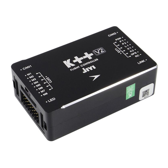
K ++ Flight Controller User
Manual
K ++
Flight Control Manual
V1.0.6
11/24/2019
Thank you in advance for purchasing this product! Please install
this product on your aircraft in strict accordance with the
requirements of the instruction manual. I wish you a happy use.
Note: This manual needs to be used in conjunction with the corresponding
assistant software. If there is any discrepancy with the assistant software, please
refer to the assistant software.
If you encounter problems that cannot be solved during use, please contact Jiyi
Robotics (Shanghai) Co., Ltd. technical support or after-sales personnel. Contact
number: 18721548648; QQ group: 458942467.
Advertisement
Table of Contents

Related Manuals for JIYI K++

Summary of Contents for JIYI K++
- Page 1 If there is any discrepancy with the assistant software, please refer to the assistant software. If you encounter problems that cannot be solved during use, please contact Jiyi Robotics (Shanghai) Co., Ltd. technical support or after-sales personnel. Contact...
- Page 2 Disclaimer Warm reminder: Jiyi K ++ flight controller is not a toy, please read this statement carefully before using it, it means that you acknowledge and accept this statement, this product is not suitable for users under 18 years old.
- Page 3 8. The user flies in bad weather conditions that are not suitable for flight; 9. The user disassembles and modifies the products and accessories produced by Jiyi Company without permission, which causes the aircraft to malfunction. 10. The user flies under the condition of objective factors such as poor mental state caused by subjective behaviors such as drinking and drug use, or problems with his own health;...
-
Page 4: Standard List
Product List 1. Standard list Before using this product, please carefully check whether the following items are contained in the product package. If it is missing, please contact us. - Page 5 2. Matching list...
- Page 6 Flight control kit basic parameters Basic parameters...
- Page 7 K ++ master control installation 1.1 K ++ main control wiring diagram 1.2 K ++ installation location requirements 1). It needs to face up, not upside down, and try to keep it parallel to the fuselage; 2). In order to obtain the best flight effect, it is recommended to install the flight control level at the center of gravity of the aircraft.
-
Page 8: Installation Location Requirements
3.2 Installation location requirements 1). It needs to face up, not upside down, and try to keep it parallel to the fuselage; 2). In order to obtain the best flight effect, it is recommended to install the flight control level at the center of gravity of the aircraft. -
Page 9: Gps Module Installation
GPS module installation 4.1 Requirements for installation direction As shown in the figure, select one of the installation directions, and select the corresponding configuration in the Basic-> Installation-> GPS Direction interface in the K ++ Assistant Software. (The direction of the red arrow represents the head direction) 4.2 Installation location requirements 1). - Page 10 Assistant software download Before using this product, you need to download and install Jiyi K ++ Flight Controller Assistant Software http://www.jiyiuav.com/download.html Note: Jiyi K ++ Flight Control Assistant Software supports computers with Windows versions above Win7 , and does not support mobile phone installation.
- Page 11 As shown in the figure, click the USB connection icon in the middle of the interface to use it normally. Assistant Software Introduction Jiyi K ++ flight control software includes four functional interfaces: viewing, basic, advanced and tools. 1. View interface The viewing interface is mainly used for reading and viewing parameters.
-
Page 12: Basic Interface
2. Basic interface Basic interface, including rack selection, installation direction selection, power configuration settings, remote controller parameter settings, sensor data reading and calibration, and flight parameter setting functions. - Page 13 3. Advanced function interface The advanced function interface includes advanced sensitivity, protection functions, pump settings, level gauges, plant protection functions, fence modules and expansion modules. 4. Tool interface The tool interface mainly includes the functions of upgrading flight control firmware, restoring factory settings, importing and exporting flight control parameters, downloading flight logs, and registering flight control manufacturers and aircraft models.
-
Page 14: Basic Function Settings
Basic function settings The flight controller is installed on the aircraft for the first time, and you can use the assistant software to perform the following basic function setting steps before normal flight. 1. Rack selection Click to enter the basic interface of the assistant software, select the rack in the upper menu bar, as shown in the figure, and select the correct rack according to the actual flight control aircraft. -
Page 15: Installation Settings
2. Installation settings Click to enter the basic interface of the assistant software, select installation from the upper menu bar, as shown in the figure, choose the correct orientation according to the actual installation direction of the flight controller and GPS. 1) .IMU orientation The direction of the IMU is the installation direction of the flight controller. -
Page 16: Power Configuration
3) .IMU location For users with high requirements for flight performance, ordinary users can leave it alone. According to the distance between the flight controller and the center of gravity of the aircraft, fill in the IMU installation position correctly. 3. - Page 17 1). Basic sensitivity setting Basic sensitivity includes roll correction, roll damping, pitch correction, pitch damping, yaw, and vertical. It is mainly used to adjust and adapt to the rack. The function definition of each sensitivity is shown in the table. Basic sensitivity debugging steps: a.
-
Page 18: Remote Control Settings
noise increases significantly, then fine-tune the sensitivity back to normal conditions. c. Then adjust the roll / pitch correction sensitivity, press 10% slowly from low to high, until the aircraft shakes, the motor sound is abnormal or exaggerated, and then adjust the sensitivity back to normal conditions. d. - Page 19 Note: The remote control must be calibrated when using or replacing the remote control for the first time. Click the "Joystick Calibration" button to start the joystick calibration. Turn on the remote control at the same time, and move all the joysticks of the remote control back and forth between the maximum and minimum positions, and confirm that channels 1 to 4 of the remote control are roll, pitch, throttle, and yaw respectively.
- Page 20 5.Sensor Click to enter the basic interface of the assistant software, select the sensor in the upper menu bar, as shown in the figure, check the flight control IMU and GPS sensor parameters, and perform accelerometer calibration and magnetic compass calibration. When you click calibration, the assistant software will prompt Instructions, just follow the interface instructions.
- Page 21 1) .IMU calibration Place the plane horizontally and click the "IMU Horizontal Calibration" button. Calibration will be completed after 3 seconds. If the body is placed at an inclined angle during calibration, or if it is shaken, it needs to be recalibrated. 2).
- Page 22 Precautions: a. When the flying field changes, the magnetic compass needs to be recalibrated. b. Before calibration, please check if there is strong magnetic interference nearby. 6. Flight parameters Click to enter the basic interface of the assistant software, and select flight parameters in the upper menu bar.
- Page 23 Advanced feature settings Advanced function settings include advanced sensitivity, protection functions, pump settings, level gauges, plant protection functions, fence modules and expansion modules. Advanced sensitivity Click to enter the advanced interface of the assistant software, select the advanced sensitivity in the upper menu bar, as shown in the figure, set the advanced sensitivity parameters of the aircraft, etc.
- Page 24 1) .Parameter adjustment The method of parameter adjustment is shown in the table:...
- Page 25 2). Performance mode It is used to adapt to different types of racks. If flight instability occurs, different performance modes can be adjusted to achieve stable flight results. 3). Performance Orientation If the aircraft appears obvious jitter or the motor output noise is large, the performance can be adjusted to suppress vibration.
-
Page 26: Protection Function
not recommended to adjust this parameter when the aircraft does not shake very much. 2. Protection function Click to enter the advanced interface of the assistant software, and select the protection function in the upper menu bar. As shown in the figure, you can choose the low voltage protection and PMU fault protection type, set the alarm voltage, implement voltage calibration, and set the one-touch return function. -
Page 27: Water Pump Settings
3) .Alarm voltage Set the value of the primary alarm voltage and secondary alarm voltage. When the battery voltage detected by the flight control reaches the first-level alarm voltage, the flight control LED flashes yellow three times; when the detection voltage reaches the second-level alarm voltage, the yellow light flashes quickly, and the flight control will trigger the low-voltage protection behavior set by the user. - Page 28 Note: In dual-pump mode, the forward movement of the aircraft is controlled by the P1 port and the backward movement is controlled by the P2 port. 2) .Channel setting The mapping channel is used to select the channel that the remote control controls the pump.
- Page 29 2). Current level: Refresh the level gauge status in real time. 3). Drug protection: The flight control set five kinds of drug protection behaviors: none, pump off, pump off + return, pump off + hover, pump off + landing after hovering. Users can choose according to their needs. 5.
- Page 30 AB record: The user can set the AB operation point record channel corresponding to the remote control as required. The default is 8 channels. AB execution: The user sets the AB operation point execution channel corresponding to the remote control according to the needs.
- Page 31 The height limit is used to limit the flying height of the aircraft. The user can set the height of the fence and turn the height limit function on or off. 2). Distance limit: The distance limit is used to limit the horizontal distance of the aircraft.
-
Page 32: Expansion Module
7. Expansion module On this interface, you can select the type of peripherals, terrain following terrain-like radar setting, obstacle avoidance radar module setting, K-BOX status information reading, RTK parameter reading and parameter setting. Remote control function introduction 1.Unlock and lock 1) .Unlock Unlock it as shown in the figure. -
Page 33: Accelerometer Calibration
2) .Lock a. Lock now In any flight mode, the motor will stop immediately after the motor is started as shown in the figure. Note: An emergency situation occurs during the flight of the aircraft. Please perform the operation of the figure to prevent accidents. b. -
Page 34: Magnetic Compass Calibration
2). Turn the return channel to the highest position, and the remote control levers 打 (American hand) and ↗↘ (Japanese hand) flash red, green, and yellow to enter the calibration. Calibration is completed after 1-2 seconds, and the LED light flashes normally. 3 Magnetic compass calibration K ++ flight control supports remote control rod calibration magnetic compass. -
Page 35: Flight Mode Introduction
Note: Under normal circumstances, a single shot can trigger the motor sequence detection. If the position is not accurate, you need to repeat step 2 to start the four shots. 2) .Motor direction test After unlocking, the aircraft propellers run at low idle speed evenly. -
Page 36: Manual Operation Mode
positioning accuracy to meet the requirements. As shown in the figure below, when the LED indicates that the GPS status is normal GPS signal, GPS signal is good, or RTK positioning, you can unlock or enter this mode in this mode. Flight control can only be unlocked in attitude mode, other modes cannot be unlocked. -
Page 37: Working Conditions
1). Working conditions The working conditions are the same as the attitude mode. It cannot be unlocked in this mode. You need to switch to this mode first after unlocking in attitude mode. After entering the manual operation mode, the green LED flashes twice. 2). - Page 38 AB point record setting: Open the assistant software and enter "Advanced"-> "Plant protection function"-> "AB record", select the channel in the drop-down box of the mapping channel on the right. AB execution setting: K ++ supports two ways for AB execution setting.
- Page 39 Step 6: Continue spraying at the breakpoint Under the premise that the AB point record is not cleared, switching to the AB operation mode will continue the operation of the last stop of the drug point and direction. The remote control can manually control the aircraft during AB operation. 3) .Parameter setting K ++ supports assistant software and APP to set the banner and speed of AB jobs.
- Page 40 4). AB point lengthening and shortening K ++ supports extending and shortening AB points during flight. When flying from point A to point B: push the pitch stick upwards, point B stretches forward, push the pitch rod down, and point B shortens backwards;...
-
Page 41: Auto Return Mode
For detailed operation, please refer to the APP instruction manual. 5.Auto return mode The auto return mode provides safety guarantee for long distance flight and runaway protection. 1). Working conditions After the star search is completed and the positioning accuracy reaches the requirements (the red LED does not flash or the red light flashes only once), the flight controller will automatically record the current position as the home point each time the user... -
Page 42: Advanced Features
Advanced Features 1. Terrain following function Terrain following function, namely the imitation ground function, the realization of this function requires access to the imitation ground radar module. Under this function, the aircraft can maintain a relatively fixed distance from the ground for flight. The remote control can temporarily change the altitude through the throttle, but after the throttle returns to the center, the aircraft automatically returns to the set altitude. - Page 43 2. Breakpoint continuous spray function K ++ supports the function of continuous injection of breakpoints. In the case of unfinished jobs, users will automatically record the breakpoints when they pause or exit the operation mode. Continue to work or re-enter the work mode, the aircraft will automatically return to the last work breakpoint.
- Page 44 2). Execution Turn the switch of the return route from the closed position to the open position to realize one-key return. 4. Remote control runaway protection function K ++ supports setting the remote control out of control protection. 1) .Setting Before executing this function, you need to enable the out-of-control protection in the "Basic"->...
- Page 45 2). Execution After the runaway protection function is enabled, the flight controller will perform the set runaway protection behavior after the remote control signal is interrupted. 5. Out of control resume operation function K ++ supports the function of setting out of control to continue the operation so that the aircraft will continue to work after the remote control is out of control.
- Page 46 2). Execution When the out-of-control continue operation option is enabled, the out-of-control protection will not be performed after the remote control is out of control in the operation mode (AB operation, route operation), but the operation task will continue to be performed. It is recommended to use this function with the radar.
- Page 47 2). Execution After enabling the low voltage protection function, the flight controller will perform the low voltage protection behavior after the battery voltage is lower than the secondary alarm voltage. 7. Fence function K ++ supports assistant software to set the fence function. 1) .Setting Before executing this function, you need to set the height limit, distance limit and trigger behavior in the "Advanced"->...
- Page 48 2). Execution After the fence function is turned on, the aircraft will automatically perform the triggering action after reaching the set altitude and distance. 8. Log storage function K ++ supports assistant software to download flight log, which is convenient for analyzing aircraft status. 1) .Refresh In the assistant software, click "Tools"->...
- Page 49 9. Landing lock function K ++ supports the landing lock function. After the user lowers the throttle to land, the flight control will automatically lock the motor when it detects that the aircraft is landing. 10. No-fly zone function K ++ sets the airport area as a no-fly zone when it leaves the factory. If you need to lift the ban, you must first apply for lifting the ban on the app device management page, which is approved by the manufacturer.
- Page 50 K ++ will automatically switch to the safe mode when it detects GPS star drop or data abnormality to ensure the flight safety of the aircraft. In safe mode, the user can manually control the landing of the aircraft. 13. Withdrawal protection function K ++ supports withdrawal protection.
- Page 51 14.Precise spraying function K ++ can realize the precise spraying function. Users need to click on the upper right corner of the spraying butler app execution interface to select the spraying mode as precision spraying. Enter the amount of acres to achieve precise spraying. 15.Double water pump mode K ++ supports dual water pump mode.
- Page 52 16.Water pump switch control function K ++ supports remote control to control the pump switch. 1) .Setting In the assistant software "Advanced"-> "Pump Settings", select the remote control mapping channel. The default is 7 channels.
- Page 53 2). Execution In attitude mode and GPS mode, when the remote control pump control channel switch is turned on, the pump will start working, and when it is turned off, the pump will be turned off. Note: The AB operation mode and the route operation mode are controlled by the flight control autonomously.
- Page 54 Operation mode (AB operation, route operation) In the parameter setting interface, set the spray mode to linkage, and the flight control will automatically perform pump linkage control during operation. Mobile ground station instructions...
-
Page 55: Appendix 1 Led Tri-Color Light Indication Status
For detailed instructions, please refer to the detailed instruction manual of the mobile ground station. Flying Anti-Butler instruction link: http://s.jiyiuav.com/docs/ffgjapp Appendix 1 LED Tri-color Light Indication Status LED tri-color light indicates status... -
Page 56: Appendix 2 Polewing Technical Support
Appendix 2 Polewing Technical Support Polewing Technical Support... - Page 57 If you encounter problems that cannot be solved during use, you can consult Polewing Technical Support. Relevant technical information, please go to the official download section of Jiyi official website to download. Phone: 18721548648 Extreme Wing QQ Group: 458942467 Jiyi official website: www.jiyiuav.com...
Need help?
Do you have a question about the K++ and is the answer not in the manual?
Questions and answers