Table of Contents
Advertisement
Quick Links
OFFICE:
BOUTROS BLDG., 1ST BSMT, CHEIKH GHABI, BEIRUT 2068 7808
T E L : 9 6 1 1 2 1 6 9 9 4 ( 2 L I N E S ) , F A X : 9 6 1 1 3 3 9 6 0 0
HEADQUARTERS AND FACTORY:
T E L : 9 6 1 7 9 9 6 3 3 3 ( 2 L I N E S ) , F A X : 9 6 1 7 9 9 6 1 1 6
ECHNICAL SUPPORT:
961 71 996333 E-MAIL: SUPPORT@SASCONTROLLERS.COM
W W . S A S C O N T R O L L E R S . C O M
AUTOMATIC TRANSFER SWITCH CONTROLLER
OMEGA-ATS/ATSO
S. & A. S. BLDG, SEASIDE ROAD, JIEH CHOUF
V1.2b
USER'S MANUAL
FOR S/W V2.00.4 & ONWARDS
FOR S/W V3.00.4 & ONWARDS
2229
Advertisement
Table of Contents

Related Manuals for S.& A.S. OMEGA-ATS


Summary of Contents for S.& A.S. OMEGA-ATS
- Page 1 ECHNICAL SUPPORT: 961 71 996333 E-MAIL: SUPPORT@SASCONTROLLERS.COM W W . S A S C O N T R O L L E R S . C O M AUTOMATIC TRANSFER SWITCH CONTROLLER OMEGA-ATS/ATSO V1.2b USER’S MANUAL FOR S/W V2.00.4 & ONWARDS FOR S/W V3.00.4 &...
- Page 3 1. GENERAL 1.1 INTRODUCTION DESCRIPTION 1.2 FEATURES 1.3 OPERATION 2.1 MEASURED AND DISPLAYED MEASUREMENTS 2.1.1 DISPLAYED PAGES 2. FRONT 2.1.2 SYMBOLS DESCRIPTIONS PANEL DESCRIPTION 2.2 FRONT PANEL LEDS 2.3 DETECTED AND SIGNALED FAULTS 2.3.1 GENSET STATUSES 2.3.2 GENSET FAULTS 2.3.3 UTILILTY STATUSES 2.3.4 UTILITY FAULT 2.4 MENU DESCRIPTION 2.4.1 PASSWORD...
- Page 4 5.1 DATA SAMPLING AND RETRIEVAL 5. SD CARD RETRIEVAL 6. DIMENSIONS DIMENSIONS 7. APPENDIX A APPENDIX A...
-
Page 5: General Description
1. GENERAL DESCRIPTION 1. GENERAL DESCRIPTION 1.1 INTRODUCTION This module controls up to three power sources: mains and two generators (MGG). It is also possible to configure it to control mains and one generator (MG) or just two generators (GG). It features isolated measurement of the voltages and frequency on all three sources as well as the current on the load side. -
Page 6: Operation
1. GENERAL DESCRIPTION OMEGA v1.0/1.1 OMEGA v1.2 On-site Firmware Upgrade Not Available Available via USB Remote Firmware Upgrade Not Available Available via Internet Up to 100 faults if the SD card is mounted Faults history Not Available Up to 15 faults if the SD Card is not mounted New Graphical LCD Display with: Easy access to all measurements in... - Page 7 1. GENERAL DESCRIPTION When the Mains is re-established, the power is switched back with a dead transfer time “Transfer” after a restoration delay “Mains Rest.” and the genset is shut down after the elapse of the “Cooling” time. For MGG and GG installation, in case the requested genset fails to start or its contactor fails to engage or it shuts down due to any fault, the other genset will automatically start and supply the load.
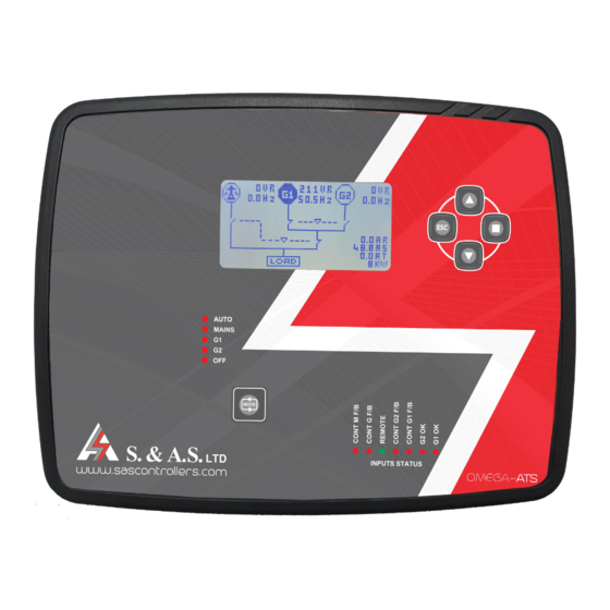
- Page 8 2. FRONT PANEL DESCRIPTION 2. FRONT PANEL DESCRIPTION 2.1 MEASURED AND DISPLAYED MEASUREMENTS 2.1.1 DISPLAYED PAGES Graphical interface showing all power sources with their contactors states, voltages, frequencies, currents and power in KW. Display Notes The line-neutral and line-line voltages are all measured.
-
Page 9: Symbols Descriptions
2. FRONT PANEL DESCRIPTION Micro SD card page showing the SD card status, data consumption and last format date. Display Ethernet page showing the Site ID, the Ethernet S/W version, revision number and the communication state. Display The UP and Down push buttons are used to scroll between the above pages. To access the parameters menu, Press and release the Select push button. - Page 10 2. FRONT PANEL DESCRIPTION 2.2 FRONT PANEL LEDS Five Leds used to indicate the operating mode. Seven input Leds used to indicate the status of the inputs. 2.3 DETECTED AND SIGNALED FAULTS 2.3.1 GENSET STATUSES Status Display Abbreviation Standby ( Not ready) Standby Standby...
- Page 11 2. FRONT PANEL DESCRIPTION 2.3.3 UTILITY STATUSES Status Display Abbreviation Standby (not ready) Standby Standby Ready Ready Ready Utility Absent Absent Absent Counting Restoring delay Restoring Rest. Engaging load (CM engaged with No CM F/B detected yet) Engaging Engaging Feeding the load (CM engaged with CM F/B detected ) Feeding Load Feeding Disengaging load CM Disengaged) with CM still detected...
-
Page 12: Accessing The Menu
2. FRONT PANEL DESCRIPTION 2.4 MENU DESCRIPTION 2.4.1 PASSWORD A password is required for accessing the menu. The password consists of 4 digits. Two passwords can access the menu. The first is provided by S. & A.S. Co. Ltd. and is referred to as client password. This password can only be changed by S. -
Page 13: Configuration Submenu
2. FRONT PANEL DESCRIPTION 2.4.4 CONFIGURATION SUBMENU What you see on the Default Description Visibility Condition Range display Value ATS: for 2 gensets of the same rating Omega Type Omega Type Client P/W ATSO: for 2 gensets of different rating Cont: for contactor outputs MCB: for motorized circuit breakers ATS Type... - Page 14 What you see on Default Description Visibility Condition Range the display Value N: Operation disabled Time Switch Time Switch operation Y: Operation enabled Ready @ Gensets ready at time “Time Switch” set to Y 8:00 AM Gensets standby at Stdby @ “Time Switch”...
-
Page 15: Utility Submenu
2. FRONT PANEL DESCRIPTION What you see on Default Description Visibility Condition Range the display Value G2 Overload % of the “Omega Type” set to G2 Overload % 0 to 100% current transformer ATSO “Omega Type” set to G2 Overld del G2 Overload delay 0 to 999 seconds ATSO... -
Page 16: Ethernet Submenu
2. FRONT PANEL DESCRIPTION 2.4.7 MODBUS SUBMENU What you see on Description Visibility Condition Range Default the display Value Modbus Modbus feature Modbus HW available N: Modbus disabled Y: Modbus enabled Slave ID Slave node ID “Modbus” set to Y 1 to 247 Baudrate Baud rate... - Page 17 2. FRONT PANEL DESCRIPTION 2.4.9 LCD DISPLAY SUBMENU What you see on Default Description Visibility Condition Range the display Value LCD Contrast LCD Contrast 0 to 30 LCD Backlight LCD Backlight 0 to 100 % 70 % percentage 2.4.10 SD CARD SUBMENU What you see on Default Description...
-
Page 18: Parameters Description
2. FRONT PANEL DESCRIPTION OMEGA v1.0/1.1 PARAMETER NAME OMEGA v1.2 PARAMETER NAME OMEGA v1.2 SUBMENU G1Alternat hrs G1 Alt. hrs GENSET SUBMENU G2Alternat hrs G2 Alt. hrs GENSET SUBMENU W.Exercise Weekly Ex. GENSET SUBMENU ATS Type ATS Type CONFIGURATION SUBMENU Installat. -
Page 19: Modbus Registers
2. FRONT PANEL DESCRIPTION 2.6 MODBUS REGISTERS Name type Address Size Access Description Omega Type Omega Type input register 30001 0 = ATS 1 = ATSO Hardware Version input register 30002 Hardware Version Software Version input register 30003 Software Version Revision number input register 30004... - Page 20 Name type Address Size Access Description 0 = Not Exercising 1 = Exercising Needed G1 Exercising status input register 30014 2 = Exercising requested 3 = Exercising stopped 0 = Not Exercising 1 = Exercising Needed G2 Exercising status input register 30015 2 = Exercising requested 3 = Exercising stopped...
-
Page 21: Terminal Description
2. FRONT PANEL DESCRIPTION 2.7 TERMINAL DESCRIPTION ONNECTOR -ve battery supply Feedback from G contactor (-ve) +ve battery supply F/B M contactor (-ve) Signal from Autostart of G1 (-ve) Output to start G1 - common Signal from Autostart of G2 (-ve) Output to start G1 - normally opened Feedback from G1 contactor (-ve) Output to start G2 - common... -
Page 22: Technical Specifications
3. TECHNICAL SPECIFICATION 3. TECHNICAL SPECIFICATIONS Supply voltage range 5 to 33Vdc Maximum supply current 190mA on 12Vdc – 95mA on 24Vdc Standby supply current 80mA on 12Vdc – 40mA on 24Vdc Digital inputs activation logic Low (ground) Output relays rating 10A 250V ac1 AC inputs range (L-N) 0 to 280Vac... - Page 23 4. FIRMWARE UPGRADE 4. FIRMWARE UPGRADE 4.1 FIRMWARE UPGRADE USING PC 1. Plug in the USB cable to the OMEGA device before turning power on 2. Turn on power of the OMEGA device. All the LEDs on the front start blinking. 3.
- Page 24 4. FIRMWARE UPGRADE Select “browse my computer” and select the downloaded windows driver. The Driver SETUP procedure will be done only once For Windows. So, the driver of any new Omega connected to the PC USB port will be installed automatically.
-
Page 25: Firmware Upgrade Process
4. FIRMWARE UPGRADE 4.1.2 INSTALLING THE FIRMWARE UPGRADE SOFTWARE In order to upgrade firmware on site, visit http://www.sascontrollers.com/applications and choose Desktop Firmware Upgrade App. 1. 64 and 32 bit folder will be downloaded respectively. 2. Run the executable file. 4.1.3 FIRMWARE UPGRADE PROCESS Run “SAS_PTool v.2.0”... - Page 26 4. FIRMWARE UPGRADE Once the upgrade is complete, a popup message “Firmware upgraded successfully” will appear: The firmware is upgraded successfully and the Omega will automatically restart.
- Page 27 4. FIRMWARE UPGRADE 4.2 FIRMWARE UPGRADE USING GOOGLE STORE ON SMART PHONE 4.2.1 INSTALLING THE SASPTOOL FIRMWARE APPLICATION ON THE MOBILE Search for the application “SASPTool” on google store and install it, or follow the link below: https://play.google.com/store/search?q=SASPTool 4.2.2 FIRMWARE UPGRADE PROCESS In order to upgrade firmware from a mobile, follow the below steps: 1.
- Page 28 4. FIRMWARE UPGRADE 5. Click on the Connect button. The following window will appear showing that a SAS Device is now connected: 6. Click on the SAS file that you need to download. A Popup window will appear showing the file name, its description and its date:...
- Page 29 4. FIRMWARE UPGRADE 7. Click Yes. The download will start: Once the download is complete, the message “Firmware Downloaded successfully” will appear:...
-
Page 30: Online Firmware Upgrade
4. FIRMWARE UPGRADE 8. Disconnect the USB cable. If you desire to delete any SAS file from the mobile list, press on the filename until a Popup window appears showing you multiple choices and then click on Delete. 4.3 ONLINE FIRMWARE UPGRADE In order to upgrade firmware remotely, the OMEGA must be connected to the internet and its status must be online &... - Page 31 4. FIRMWARE UPGRADE 8. Under Update Controller Firmware, select the “Choose Files” button to choose the online controller software to be upgraded. Double-check the filename and its extension (*_online.sas). 9. The Ethernet firmware upgrade is optional. In case it's needed, select the “Update Ethernet Firmware” checkbox, and select “Choose files”...
- Page 32 5. SD CARD RETRIEVAL 5. SD CARD RETRIEVAL In order to retrieve Event or Time logs from OMGEA v1.2, a desktop application will be provided by S. & A. S. Ltd & the below steps shall be followed: 1. Run file “Log_Retrieve_Utility_windows.exe”. 2.
- Page 33 5. SD CARD RETRIEVAL 5. If the entered password is valid, make sure the SD-CARD is considered "Mounted" and select the type required (Time Log or Event Log), then choose the Start/End dates and press the "Excel Sheet" Button.
- Page 34 5. SD CARD RETRIEVAL 6. Select the path and name for the Excel file to be exported. 7. The retrieve process should start and the progress will be indicated by an animated loader with the completed percentage. 8. Wait until the loader disappears, at this stage the progress is finished and you can find the exported file at the path specified in step #5.
- Page 35 DIMENSIONS DIMENSIONS...
- Page 36 APPENDIX A 7. APPENDIX A This appendix contains all wiring diagrams relevant to assembling the board in a panel.
- Page 42 WHICH GENERATOR CONTROLLER IS RIGHT FOR YOU? Smart Turbo v1.2 Smart GT v1.0 Surf LT v1.0 Surf 1.2c Automatic engine starting and stopping Automatic mains failure — — User Access 3 Push Buttons 3 Push Buttons 8 Push Buttons 5 Push Buttons...
- Page 43 Smart Turbo v1.2 Smart GT v1.0 Surf LT v1.0 Surf 1.2c Overload alarm and — shut down Low oil pressure alarm and shut down High engine temperature alarm and ...
- Page 44 Smart Turbo v1.2 Smart GT v1.0 Surf LT v1.0 Surf 1.2c EVENTS AND DATA — — — LOGGING USB interface CAN Module (J1939 — — Optional Protocol) Ethernet Module — — — RS485 (Modbus) —...
Need help?
Do you have a question about the OMEGA-ATS and is the answer not in the manual?
Questions and answers