Table of Contents
Advertisement
Quick Links
OFFICE:
BOUTROS BLDG., 1ST BSMT, CHEIKH‐GHABI, BEIRUT 2068 7808
T E L : 9 6 1 ‐ 1 ‐ 2 1 6 9 9 4 ( 2 L I N E S ) , F A X : 9 6 1 ‐ 1 ‐ 3 3 9 6 0 0
HEADQUARTERS AND FACTORY:
T E L : 9 6 1 ‐ 7 ‐ 9 9 6 3 3 3 ( 2 L I N E S ) , F A X : 9 6 1 ‐ 7 ‐ 9 9 6 1 1 6
TECHNICAL SUPPORT:
961‐71‐996333 E-MAIL: SUPPORT@SASCONTROLLERS.COM
W W W . S A S C O N T R O L L E R S . C O M
AUTOMATIC TRANSFER SWITCH CONTROLLER
AUTOMATIC TRANSFER SWITCH CONTROLLER
OMEGA-ATS/ATSO
OMEGA-ATS/ATSO
S. & A. S. BLDG, SEASIDE ROAD, JIEH CHOUF
.. ..
USER'S MANUAL
FOR H/W VERSION 1.2/1.2a
FOR S/W VERSION 1.0 1925
Advertisement
Table of Contents

Related Manuals for S.& A.S. OMEGA-ATS


Summary of Contents for S.& A.S. OMEGA-ATS
- Page 1 961‐71‐996333 E-MAIL: SUPPORT@SASCONTROLLERS.COM W W W . S A S C O N T R O L L E R S . C O M AUTOMATIC TRANSFER SWITCH CONTROLLER AUTOMATIC TRANSFER SWITCH CONTROLLER OMEGA-ATS/ATSO OMEGA-ATS/ATSO ..USER’S MANUAL FOR H/W VERSION 1.2/1.2a...
-
Page 3: General Description
4. FIRMWARE 4. FIRMWARE 2. FRONT PANEL 2. FRONT PANEL 3. TECHNICAL 3. TECHNICAL 1 .GENERAL DESCRIPTION 1 .GENERAL DESCRIPTION UPGRADE UPGRADE SPECIFICATIONS SPECIFICATIONS DESCRIPTION DESCRIPTION 1.1 INTRODUCTION 2.1 MEASURED AND DISPLAYED 3. TECHNICAL SPECIFICATIONS 4.1 INSTALLING THE SAS DEVICE 1.2 FEATURES MEASUREMENTS FIRMWARE UPGRADE SOFTWARE... - Page 4 1 .GENERAL DESCRIPTION 1 .GENERAL DESCRIPTION 1. GENERAL DESCRIPTION 1. GENERAL DESCRIPTION 1.1 INTRODUCTION 1.1 INTRODUCTION This module controls up to three power sources: mains and two generators (MGG). It is also possible to configure it to control mains and one generator (MG) or just two generators (GG). It features isolated measurement of the voltages and frequency on all three sources as well as the current on the load side.
- Page 5 1 .GENERAL DESCRIPTION 1 .GENERAL DESCRIPTION OMEGA v1.0/1.1 OMEGA v1.2 On-site Firmware Upgrade Not Available Available via USB Remote Firmware Upgrade Not Available Available via Internet Up to 100 faults if the SD card is mounted Faults history Not Available Up to 15 faults if the SD Card is not mounted New Graphical LCD Display with: Easy access to all measurements in...
-
Page 6: Operation
1 .GENERAL DESCRIPTION 1 .GENERAL DESCRIPTION 1.3 OPERATION 1.3 OPERATION Four operating modes are provided. To switch from one mode to another, press the mode push button till you reach the required operating mode and then wait for 2 seconds for the operating mode to be applied. Following is description of the operating modes: •... -
Page 7: Terminal Description
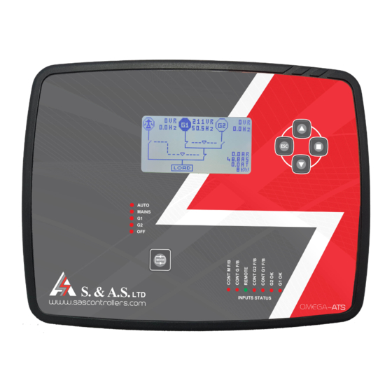
2. TERMINAL 2. TERMINAL DESCRIPTION DESCRIPTION 2. FRONT PANEL DESCRIPTION 2. FRONT PANEL DESCRIPTION 2.1 MEASURED AND DISPLAYED MEASUREMENTS 2.1 MEASURED AND DISPLAYED MEASUREMENTS 2.1.1 DISPLAYED PAGES 2.1.1 DISPLAYED PAGES • Graphical interface showing all power sources with their contactors states, voltages, frequencies, currents and power in KW. -
Page 8: Symbols Descriptions
2. TERMINAL 2. TERMINAL DESCRIPTION DESCRIPTION • Micro SD card page showing the SD card status, data consumption and last format date. Display Display • Ethernet page showing the Site ID, the Ethernet S/W version, revision number and the communication state. -
Page 9: Front Panel Leds
2. TERMINAL 2. TERMINAL DESCRIPTION DESCRIPTION 2.2 FRONT PANEL LEDS 2.2 FRONT PANEL LEDS • Five Leds used to indicate the operating mode. • Seven input Leds used to indicate the status of the inputs. 2.3 STATUS AND FAULTS 2.3 STATUS AND FAULTS 2.3.1 GENSET STATUSES 2.3.1 GENSET STATUSES Status... - Page 10 2. TERMINAL 2. TERMINAL DESCRIPTION DESCRIPTION 2.3.3 UTILITY STATUSES 2.3.3 UTILITY STATUSES Status Display Abbrevia on Standby (not ready) Standby Standby Ready Ready Ready U lity Absent Absent Absent Coun ng Restoring delay Restoring Rest. Engaging load (CM engaged with No CM F/B detected yet) Engaging Engaging Feeding the load (CM engaged with CM F/B detected )
-
Page 11: Accessing The Menu
2. TERMINAL 2. TERMINAL DESCRIPTION DESCRIPTION 2.4 MENU DESCRIPTION 2.4 MENU DESCRIPTION 2.4.1 PASSWORD 2.4.1 PASSWORD A password is required for accessing the menu. The password consists of 4 digits. Two passwords can access the menu. The first is provided by S. & A.S. Co. Ltd. and is referred to as client password. This password can only be changed by S. -
Page 12: Configuration Submenu
2. TERMINAL 2. TERMINAL DESCRIPTION DESCRIPTION 2.4.4 CONFIGURATION SUBMENU 2.4.4 CONFIGURATION SUBMENU What you see on the Descrip on Visibility Condition Range Default Value display ATS: for 2 gensets of the same ra ng Omega Type Omega Type Client P/W ATSO: for 2 gensets of different ra ng Cont: for contactor outputs MCB: for motorized circuit breakers... - Page 13 2. TERMINAL 2. TERMINAL DESCRIPTION DESCRIPTION What you see on the Descrip on Visibility Condition Range Default Value display (Warm up +Transfer dead me+10) to Start Fail Start fail delay 45 sec 999 sec N: Start order released a er start failure Hold Start Hold Start feature...
-
Page 14: Utility Submenu
2. TERMINAL 2. TERMINAL DESCRIPTION DESCRIPTION What you see on Descrip on Visibility Condition Range Default Value the display G2 Overload % of the G2 Overload % “Omega Type” set to ATSO 0 to 100% current transformer G2 Overld del G2 Overload delay “Omega Type”... -
Page 15: Ethernet Submenu
2. TERMINAL 2. TERMINAL DESCRIPTION DESCRIPTION 2.4.7 MODBUS SUBMENU 2.4.7 MODBUS SUBMENU What you see on Descrip on Visibility Condition Range Default Value the display Modbus Modbus feature Modbus HW available N: Modbus disabled Y: Modbus enabled Slave ID Slave node ID “Modbus”... - Page 16 2. TERMINAL 2. TERMINAL DESCRIPTION DESCRIPTION 2.4.9 LCD DISPLAY SUBMENU 2.4.9 LCD DISPLAY SUBMENU What you see on Descrip on Visibility Condition Range Default Value the display LCD Contrast LCD Contrast 0 to 30 LCD Backlight LCD Backlight 0 to 100 % 70 % percentage 2.4.10 SD CARD SUBMENU...
-
Page 17: Parameters Description
2. TERMINAL 2. TERMINAL DESCRIPTION DESCRIPTION OMEGA v1.0/1.1 PARAMETER NAME OMEGA v1.2 PARAMETER NAME OMEGA v1.2 SUBMENU G1Alternat hrs G1 Alt. hrs GENSET SUBMENU G2Alternat hrs G2 Alt. hrs GENSET SUBMENU W.Exercise Weekly Ex. GENSET SUBMENU ATS Type ATS Type CONFIGURATION SUBMENU Installat. -
Page 18: Modbus Registers
2. TERMINAL 2. TERMINAL DESCRIPTION DESCRIPTION 2.6 MODBUS REGISTERS 2.6 MODBUS REGISTERS Name type Address Size Access Descrip on Omega Type Omega Type input register 30001 0 = ATS 1 = ATSO Hardware Version input register 30002 Hardware Version So ware Version input register 30003 So ware Version... - Page 19 2. TERMINAL 2. TERMINAL DESCRIPTION DESCRIPTION Name type Address Size Access Descrip on 0 = Not Exercising 1 = Exercising Needed G1 Exercising status input register 30014 2 = Exercising requested 3 = Exercising stopped 0 = Not Exercising 1 = Exercising Needed G2 Exercising status input register 30015...
- Page 20 2. TERMINAL 2. TERMINAL DESCRIPTION DESCRIPTION 2.6 TERMINAL DESCRIPTION 2.6 TERMINAL DESCRIPTION ONNECTOR -ve ba ery supply Feedback from G contactor (-ve) +ve ba ery supply F/B M contactor (-ve) Signal from Autostart of G1 (-ve) Output to start G1 - common Signal from Autostart of G2 (-ve) Output to start G1 - normally opened Feedback from G1 contactor (-ve)
-
Page 21: Technical Specifications
3. TECHNICAL 3. TECHNICAL SPECIFICATIONS SPECIFICATIONS 3. TECHNICAL SPECIFICATIONS 3. TECHNICAL SPECIFICATIONS Supply voltage range 5 to 33Vdc Maximum supply current 190mA on 12Vdc – 95mA on 24Vdc Standby supply current 80mA on 12Vdc – 40mA on 24Vdc Digital inputs ac va on logic Low (ground) Output relays rating 10A 250V ac1... -
Page 22: Firmware Upgrade
4. FIRMWARE 4. FIRMWARE UPGRADE UPGRADE 4. FIRMWARE UPGRADE 4. FIRMWARE UPGRADE 4.1 INSTALLING THE SAS DEVICE FIRMWARE UPGRADE SOFTWARE 4.1 INSTALLING THE SAS DEVICE FIRMWARE UPGRADE SOFTWARE In order to upgrade firmware on site, a CD will be provided by S. &A.S.Ltd & the below steps shall be followed: 1. - Page 23 4. FIRMWARE 4. FIRMWARE UPGRADE UPGRADE Select “Search automatically for updates driver software”.
- Page 24 4. FIRMWARE 4. FIRMWARE UPGRADE UPGRADE Select install this driver software anyway. The Driver SETUP procedure will be done only once For Windows vista/Win7. So, the driver of any new SAS Device connected to the PC USB port will be installed automatically. 4.2.2 DRIVER SETUP FOR WINDOWS XP 4.2.2 DRIVER SETUP FOR WINDOWS XP Each time New SAS Device is plugged into the PC USB port, a “Found New Hardware Wizard”...
-
Page 25: Firmware Upgrade Process
4. FIRMWARE 4. FIRMWARE UPGRADE UPGRADE The driver of the new SAS Device connected to the PC USB port will be installed automatically. 4.3 FIRMWARE UPGRADE PROCESS 4.3 FIRMWARE UPGRADE PROCESS Run “SAS_PTool” application. The following window will appear prompting the user that the SAS board is detected on the USB port: Click Open to choose the *.sas file that will be used to upgrade the firmware. - Page 26 4. FIRMWARE 4. FIRMWARE UPGRADE UPGRADE The upgrade progress is shown as below: Once the upgrade is complete, the footnote “Firmware upgraded successfully” will appear: Then the SAS device firmware upgraded successfully, and the SAS device will automatically run the new firmware.
- Page 27 4. FIRMWARE 4. FIRMWARE UPGRADE UPGRADE 4.4. FIRMWARE UPGRADE USING GOOGLE PLAY STORE ON SMART PHONE 4.4. FIRMWARE UPGRADE USING GOOGLE PLAY STORE ON SMART PHONE 4.4.1 INSTALLING THE SASPTOOL FIRMWARE APPLICATION ON THE MOBILE 4.4.1 INSTALLING THE SASPTOOL FIRMWARE APPLICATION ON THE MOBILE In order to upgrade the firmware from your mobile, follow the below steps: 1.
- Page 28 4. FIRMWARE 4. FIRMWARE UPGRADE UPGRADE Power off the SAS board Use a USB cable to connect board to the mobile. Turn SAS device on. The following window will appear showing that a SAS Device is now connected: Click on the sas file that you need to download. POPUP POPUP window will appear showing the file name, its description and its date:...
- Page 29 4. FIRMWARE 4. FIRMWARE UPGRADE UPGRADE Once the download is completed, the message “Firmware downloaded successfully” will appear: Disconnect the USB cable. The user can now process with normal operation. If you desire to delete any sas file from the mobile list, press and hold on the filename until a POPUP POPUP window...
-
Page 30: Online Firmware Upgrade
4. FIRMWARE 4. FIRMWARE UPGRADE UPGRADE 4.3 ONLINE FIRMWARE UPGRADE 4.3 ONLINE FIRMWARE UPGRADE In order to upgrade firmware remotely, the OMEGA must be connected to the internet and its status must be online & the below steps shall be followed: Run the OMEGA Web application on our website www.sascontrollers.com. - Page 31 4. FIRMWARE 4. FIRMWARE UPGRADE UPGRADE Under Update Controller Firmware, select “Choose Files” button to choose the online controller software to be upgraded. Double check the filename and its extension (*_online.sas). The Ethernet firmware upgrade is optional. In case it's needed, select the “Update Ethernet Firmware”...
- Page 32 5. SD CARD 5. SD CARD RETRIEVAL RETRIEVAL 5. SD CARD RETRIEVAL 5. SD CARD RETRIEVAL In order to retrieve Event or Time logs from OMGEA v1.2, a desktop application will be provided by S. & A. S. Ltd & the below steps shall be followed: Run file “Log_Retrieve_Utility_windows.exe”.
- Page 33 5. SD CARD 5. SD CARD RETRIEVAL RETRIEVAL If the entered password is valid, make sure the SD-CARD is considered "Mounted" and select the type required (Time Log or Event Log), then choose the Start/End dates and press the "Excel Sheet" Button. Select the path and name for the Excel file to be exported.
- Page 34 5. SD CARD 5. SD CARD RETRIEVAL RETRIEVAL The retrieve process should start and the progress will be indicated by an animated loader with the completed percentage. Wait until the loader disappears, at this stage the progress is finished and you can find the exported file at the path specified in step #5.
- Page 35 6. DIMENSIONS 6. DIMENSIONS & TYPICAL WIRING & TYPICAL WIRING DIAGRAM DIAGRAM DIMENSIONS & TYPICAL WIRING DIAGRAM • • DIMENSIONS DIMENSIONS • • TYPICAL WIRING DIAGRAM TYPICAL WIRING DIAGRAM...
- Page 36 DC Inputs ST.G2 Note 2 Note 2 Note 1: External contact supplied from the autostart of the genset: ST.G1 ST.G1 ST.G2 ST.G2 Contact closed: Genset is running & ready to supply the load (no need for OMEGA v1.2a Board warm-up delay). Contact open: Genset has a fault or cannot supply the load.
- Page 37 DC Inputs with MCB/MCO ST.G2 Note 2 Note 2 Note 1: External contact supplied from the autostart of the genset: ST.G1 ST.G1 ST.G2 ST.G2 OMEGA v1.2a Board Contact closed: Genset is running & ready to supply the load (no need for warm-up delay).
- Page 38 AC Inputs Main Supply LINE LINE LINE LINE LINE LINE LINE LINE LINE Main R G2 S G2 T G2 R G1 S G1 T G1 CTR - P1 OMEGA v1.2a Board Line R CTR - P2 CTS - P1 Current transformers installed on Load Side Line S CTS - P2...
- Page 39 AC OUTPUTS with Contactors LINE R G2 LINE R G LINE R M LINE R G1 (Taken from output of CG1 & CG2) Single line diagram FUSE FUSE FUSE FUSE OMEGA v1.2a Board LOAD D.NO D.NC D.NO D.NC D.NO D.NC Note 1: Used as an alarm output if fault exists on G1 or G2 in case NOTE 3 NOTE 4...
- Page 40 AC OUTPUTS with MCB/MCO LINE R G2 LINE R M LINE R G1 FUSE FUSE FUSE Single line diagram OMEGA v1.2a Board MCB/MCO-M MCB/MCO-G1 MCB/MCO-G2 D.NO D.NC D.NO D.NC D.NO D.NC NOTE 3 NOTE 4 NOTE 3 NOTE 4 NOTE 3 NOTE 4 LOAD MCB/MCO-G1...
- Page 41 WHICH GENERATOR CONTROLLER IS RIGHT FOR YOU? Smart Turbo v1.2 Smart GT v1.0 Surf LT v1.0 Surf 1.2c Automatic engine starting and stopping Automatic mains failure — — User Access 3 Push Buttons 3 Push Buttons 8 Push Buttons 5 Push Buttons...
- Page 42 Smart Turbo v1.2 Smart GT v1.0 Surf LT v1.0 Surf 1.2c Overload alarm and — shut down Low oil pressure alarm and shut down High engine temperature alarm and ...
- Page 43 Smart Turbo v1.2 Smart GT v1.0 Surf LT v1.0 Surf 1.2c EVENTS AND DATA — — — LOGGING USB interface CAN Module (J1939 — — Optional Protocol) Ethernet Module — — — RS485 (Modbus) —...
Need help?
Do you have a question about the OMEGA-ATS and is the answer not in the manual?
Questions and answers