Table of Contents
Advertisement
Quick Links
D-25 Continuous mixer
User Manual
Electric
#60010054 ASSY, MIXER, CONTINUOUS-D25-132LB
#60010085 ASSY, MIXER, CONTINUOUS-D25-78LB
#60010093 ASSY, MIXER, CONTINUOUS-D25-2"
#60010084 ASSY, MIXER, CONTINUOUS-D25-132LB-3 PHASE
#60010108 ASSY, MIXER, CONTINUOUS-D25-78LB-3 PHASE
#60010098 ASSY, MIXER, CONTINUOUS-D25-2"-3 PHASE
#60010106 ASSY, MIXER, CONTINUOUS-D25-132LB-480V-3 PHASE
#60010099 ASSY, MIXER, CONTINUOUS-D25-78LB-480V-3 PHASE
#60010107 ASSY, MIXER, CONTINUOUS-D25-2"-480V-3 PHASE
REV-6 08/30/08
620, County Road 4841. Haslet, TX 76052
Ph 817.439.1108
Fax 817.439.0633
www.machine-technologies.com
Advertisement
Table of Contents

Summary of Contents for machine technologies D-25
- Page 1 D-25 Continuous mixer User Manual Electric #60010054 ASSY, MIXER, CONTINUOUS-D25-132LB #60010085 ASSY, MIXER, CONTINUOUS-D25-78LB #60010093 ASSY, MIXER, CONTINUOUS-D25-2" #60010084 ASSY, MIXER, CONTINUOUS-D25-132LB-3 PHASE #60010108 ASSY, MIXER, CONTINUOUS-D25-78LB-3 PHASE #60010098 ASSY, MIXER, CONTINUOUS-D25-2"-3 PHASE #60010106 ASSY, MIXER, CONTINUOUS-D25-132LB-480V-3 PHASE #60010099 ASSY, MIXER, CONTINUOUS-D25-78LB-480V-3 PHASE #60010107 ASSY, MIXER, CONTINUOUS-D25-2"-480V-3 PHASE...
- Page 2 Dear Customer, Before starting this machine please complete the following; Machine Date of purchase………………………………….. Machine serial number……………………………………… Please read the following information contained within this manual and fully familiarize yourself with the equipment. Page 2...
-
Page 3: Table Of Contents
Contents Page Section 1 - General Safety information................4 Danger..........................4 Section 2 - Machine Description ..................5 Function.......................... 5 Machine illustrations..................... 6 Machine ........................6 Base Frame assembly ....................7 Hopper unit......................... 8 Mixing Nozzle Assembly.................... 9 Assy,Breaker-Dosing-Mix-D25 ................10 Dosing / Feed screw - 60010069 - ASSY,HELIX-CONT MIXER-132LB... -
Page 4: Section 1 - General Safety Information
Ensure that the breaker assembly is free to rotate within the nozzle assembly prior to starting the machine. The D-25 continuous mixer unit can produce high torques and can use high voltages. Care must be taken by authorized persons when using and working with this machine. -
Page 5: Section 2 - Machine Description
Section 2 - Machine Description Function The continuous mixer uses pre-bagged, pre blended material, that is broken via the bag breaker on the hopper, and poured into the hopper, that then discharges into the nozzle and mixes it with water, to provide a usable mixture at its outlet. The machine has a drive motor, that turns a drive shaft within a material hopper that in turn rotates a helical feed screw, in turn rotating a mixing shaft. -
Page 6: Machine Illustrations
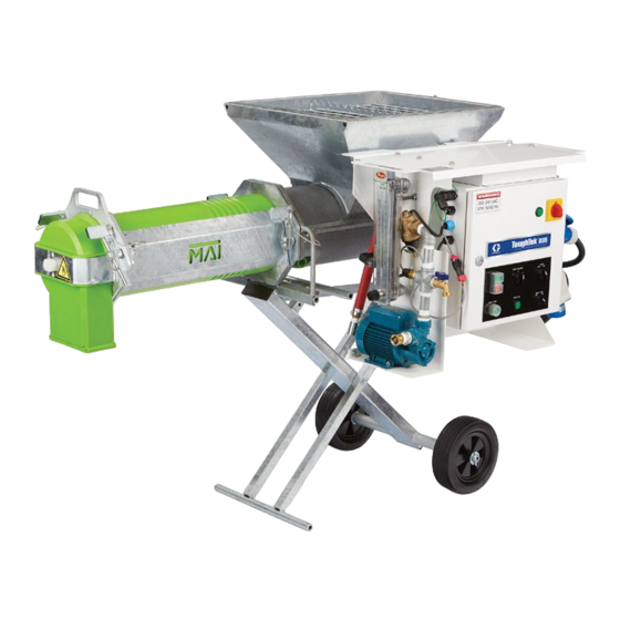
Machine illustrations Machine 1 – Hopper unit 2 – Mixing nozzle assembly 3 – Base frame assembly 4 – Inverter drive module 5 – Drive motor 6- Water control module 7- Bag Breaker. 8 – Water hose assy 9 – Power cord and socket. Page 6... -
Page 7: Base Frame Assembly
Base Frame assembly The base frame can be re-configured to have the wheels, axle etc. located at the opposite end of the unit, with the handle thus also being mirrored. The control panel assembly on handle assembly can be moved, by pulling the pins keeping the handle assembly in place in the frame, then sliding the handle out, allowing access to the control box itself 1 –... -
Page 8: Hopper Unit
Hopper unit Page 8... -
Page 9: Mixing Nozzle Assembly
Mixing Nozzle Assembly – 132LB shown (60010056). The complete mixing nozzle assembly is available in three different versions, low output (78LB), standard output (132LB) and High output (2”). Page 9... -
Page 10: Assy,Breaker-Dosing-Mix-D25
Assy,Breaker-Dosing-Mix-D25 - 132LB shown (60010066). Alternatively, the complete Assy, Breaker-dosing-mix is available in three different versions, Low output (78LB) 6001007, Standard output (132LB) 60010066-shown, and High output (2”) 60010091 Page 10... -
Page 11: Dosing / Feed Screw - 60010069 - Assy,Helix-Cont Mixer-132Lb
The primary difference between ALL the various combinations of low, standard and high output shaft, tube etc. assemblies is the dosing / feed screw Dosing / Feed screw - 60010069 - ASSY,HELIX-CONT MIXER-132LB Dosing / Feed screw - 60010074 - ASSY,HELIX-CONT MIXER-78LB Dosing / Feed screw - 60010088 - ASSY,HELIX-CONT MIXER-2"... -
Page 12: Wear Liner Assembly, Seal, Seal Clamp, Bolts And Washers
Wear liner assembly, Seal, Seal clamp, Bolts and Washers Page 12... -
Page 13: Electronic Drive Module
220VAC two phase to run the high torque 3 Phase gear motor. The unit is rated at 4KW providing plenty of power to run the D-25 unit. The module is supplied with an input plug allowing immediate wiring into your own 220VAC 2 phase supply (Must be carried out by an approved installer). - Page 14 To access the control box, remove the two pins from either side of the frame assembly, and withdraw the handle with the control box mounted to it from the main frame. Do not fully withdraw the handle and box, as damage could result from dropping to the ground. Page 14...
-
Page 15: Drive Motor Unit
Drive motor unit The machine is supplied with an electric motor drive. Page 15... -
Page 16: Water Control Module
Water Control Module The water control module allows the hook up of a typical water feed to the inlet port. When the solenoid is turned on via the connector from the control box water flows through the inline pressure regulator through the solenoid valve into the adjustable visual flow meter, and out though the outlet connector. -
Page 17: Section 3 - Transportation And Positioning
Section 3 – Transportation and positioning The machine is typically manually transported around the job site by dropping and locking the wheels in the down position, then using the nozzle like the handles on a wheel barrow. Lift the machine at the wheel end, and lift UP the axle lock bar and the wheels will drop to the ground. - Page 18 Once in position, the lock bar can be raised, and the whole unit will drop, lifting the axle and the wheels. The lock bar, on level ground, will catch the axle to keep it from lowering. Page 18...
-
Page 19: Section 4 - Machine Set Up
Section 4 – Machine set up Unpacking and assembly Consult the final inspection record supplied in the packing for details of your machine and the items checked prior to shipment. Keep this document for your records. Remove the unit from the packing and the pallet. If required, Pre assemble the motor assembly onto the rear of the hopper, hanging it on the location rods. - Page 20 Remove the safety grid from the top of the hopper, to allow you to rotate the breaker bar assembly already fitted inside the unit. If required, rotate the breaker bar in the hopper to engage the flat end into the slot in the drive / hauling bracket of the motor assembly.
- Page 21 Assemble the breaker bar into the hauling bracket, and secure with the bolt provided. This bolt is only intended to prevent the breaker bar from becoming decoupled when the nozzle is removed. Page 21...
- Page 22 If required, Assemble the feed screw assembly over the end of the breaker bar, from the front of the hopper. Rotate the feed screw round until the hole in the breaker bar and the holes in the feed screw align. Once aligned, then the roll pin must be “driven” into the holes until it sticks out either end by approx ¼”.
- Page 23 Assemble the front section of the mixing shaft to the fitted two rear sections of the full breaker / mixer assembly. Ensure that the cross pin is aligned with the slot in the front of the metering shaft (fitted within the hopper / wear liner assembly). Remove the two wedges from the front of the hopper, using a hammer (if required), Page 23...
- Page 24 Grease the edge of the seal, and assemble the nozzle. Assemble the nozzle over the end of the mixer shaft, along its length, then over the wear liner assembly, ensure that the end of the mixing shaft locates into the bearing in the end of the nozzle tube.
- Page 25 Assemble wedges using a hammer. ENSURE that the nozzle flange is parallel with the hopper flange Re-assemble the safety grid to the top of the hopper, using the grid keepers and bolts originally fitted. Ensure that the bag breaker is fitted to the grid and is facing upwards (CAUTION as the sharp edge can cause injury), if not already fitted Operation of this machinery without the grid in place is prohibited!! Page 25...
-
Page 26: Electrical Connections
Electrical connections 1. Ensure that there are no power connections to the Electronic drive module. 2. Connect the motor power plug into the socket on the control box under the hopper. 3. Ensure that the water solenoid connector from the control box is plugged onto the water solenoid. - Page 27 The following must be conducted by a supervisor or a qualified individual experienced in electro-mechanical equipment. Ensure that there are no persons close to the machine. Ensure that there are no obstructions in or around the machine. Turn the speed control knob fully clockwise Max speed = 280 RPM (normal configuration).
-
Page 28: Section 5 - Machine Operation / Speed Setting
The following are to be completed by trained and experienced persons, familiar with the mixing system provided. 1. Fill the D-25 hopper with material. By dropping bags over the bag breaker, twisting left and right by approx 15 degrees, then lifting both ends of the bag to tear it in the middle. -
Page 29: Section 6 - Maintenance
Section 6 – Maintenance Wear parts It is normal for wear to occur on the mixing shaft, and in the mixing nozzle. The rate of wear is very dependant upon the materials being mixed and the throughput of the machine. The feed / metering section of the mixing shaft is also subject to wear, as is the wear line assembly The mixing shaft is made of 3 sections each part is individually replaceable. -
Page 30: Limited Warranty Policy
LIMITED WARRANTY POLICY Machine Technologies warrants each of its new machines to be free of defects in material and workmanship under normal use and services for a period of one (1) year from the date of delivery. The warranty is issued ONLY to the INITIAL USER. The warranty period begins when the product is delivered to the initial user or when first put into service, whichever occurs first.
Need help?
Do you have a question about the D-25 and is the answer not in the manual?
Questions and answers