
Related Manuals for UniPi Technology Patron S107


Summary of Contents for UniPi Technology Patron S107
- Page 1 Automation Monitoring and control Remote access and management HVAC Unipi Patron Product line of programmable controllers www.unipi.technology...
-
Page 2: Table Of Contents
User guide and technical documentation Contents Introduction ............................3 What is Unipi Patron? ......................3 What can be Unipi Patron used for?..................3 Which Patron models are available? ..................3 Patron product line structure ....................4 Compliance with directives ...................... 4 Installation and connection ...................... - Page 3 User guide and technical documentation Technical parameters ........................23 Digital inputs .......................... 23 Digital outputs ........................23 Analog inputs ......................... 23 Analog outputs ........................24 Relay outputs ......................... 24 RS-485 Interface........................25 RS-232 Interface........................25 Storage, installation and working conditions ................. 25 Dimensions ..........................
-
Page 4: Introduction
User guide and technical documentation 1 Introduction 1.1 What is Unipi Patron? Unipi Patron is a product line of compact freely programmable controllers (hereafter units) for automatic regulation and monitoring. It is designed for operation in residential and commercial premises and light industry areas, except for systems which are critical for security. -
Page 5: Patron Product Line Structure
User guide and technical documentation 1.4 Patron product line structure Each Patron unit is divided into one to three sections depending on the specific unit type. Sections are always numbered from right to left of the main section (1). Each section contains inputs, outputs, or communication interfaces, which are always numbered from the left separately within the section. -
Page 6: Installation And Connection
User guide and technical documentation 2 Installation and connection 2.1 Basic instructions and safety information Always follow these instructions during the installation: • All connected external peripherals should comply with all relevant directives and standards applicable to the method of use and the country in which the unit is used •... -
Page 7: Description Of Connectors And Indication Leds
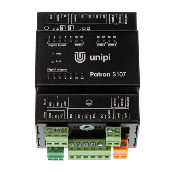
User guide and technical documentation 2.3 Description of connectors and indication LEDs 2.3.1 LEDs indication Name Function Meaning Colour Supply voltage indication Blinking Section status indication Green Digital inputs (DI) Indication of log.1 at the input Green Digital outputs (DO) Output switch indication Green Relay outputs (RO) -
Page 8: Connector Description
User guide and technical documentation 2.3.2 Connector description Terminal label Meaning +24V Positive pole of power supply Negative pole of power supply Digital input DIGND Digital input common terminal – negative pole Digital output DOGND Digital output common terminal – negative pole Relay output Common relay terminal Analog input... - Page 9 User guide and technical documentation To install unit on the DIN rail, slide the unit onto the rail from above (in the direction of arrow 1 in the picture below), against the spring resistance downwards and then clicking the lower part (in the direction of arrow 2 in the picture below).
-
Page 10: Connection
User guide and technical documentation Caution: Avoid pressure on the inputs/outputs as they could be mechanically damaged. 2.4.2 Connection There are pluggable screw terminals for the connection of any cable. Purpose of each terminal block contact is depicted on the top side of the unit case. For wire montage into screw terminals always use appropriate flat head screwdriver. -
Page 11: Digital Input Connection - Di
User guide and technical documentation 2.4.4.3 1-Wire 1-Wire bus purpose is data collection from the connected sensors, e.g. thermometer, humidity sensor. The connection is made to a detachable screw connector marked 1-Wire with GND, 1W, VCC terminals. Connecting multiple devices to the 1-Wire bus is done in series (i.e. from sensor to sensor), or using a reduction and hub with RJ45 connectors (Cable 1-Wire reduction –... -
Page 12: Digital Output Connection - Do
User guide and technical documentation 2.4.6 Digital output connection – DO Digital outputs (semiconductor, connected as open collectors) are accessible through DOx (DOy.x) and DOGND digital output terminals. All digital outputs have common screw connector DOGND for negative pole connection of direct current power supply. Screw connector of DOx serves for connection of a load that switches the output to a common potential. - Page 13 User guide and technical documentation Negative pole of measured external device is connected to screw connector of AGND while positive pole is connected to screw AIy.x connector. Note: By default, the unit is set to voltage measurement to avoid potential device/sensor damage in case of inappropriate connection.
-
Page 14: Analog Output Connection - Ao
User guide and technical documentation 2.4.7.2 Analog inputs – AIy.x These analog inputs on sections 2 and 3 have an accurate measurement of voltage, current or resistance. The measurement mode must be set for each analog input in the chosen software (see chapter 3) according to the following table: Settings Type of measurement... -
Page 15: Relay Output Connection - Ro
User guide and technical documentation The connection of the PT1000 temperature sensor to the AOR is illustrated on the following figure: 2.4.8.2 Voltage analog outputs – AOV These analog outputs only allow output in the form of a voltage source, i.e. 0–10 V. The values are of the WORD type in the range 0 to 4000. - Page 16 User guide and technical documentation Note: In case of connected inductive load (such as electromotor, coil of a relay or contactor or even power cabling in complex electro installations) it is recommended to protect relay outputs with an appropriate external component (e.g.
-
Page 17: Software
An mDNS record is simultaneously published into the network, making the unit available under a unique name. E.g: Patron S107 with serial number 123, would be accessible at "http://s107- sn123.local". The serial number can be found on the unit’s product label. -
Page 18: Service Mode
User guide and technical documentation 3.1.2 Service mode Service mode is a web tool for IP configuration, (de)activation of Mervis and SSH services, reflashing of OS images, creation of OS backup to USB flash drive and other useful functions. To activate the service mode, follow these steps: 1. -
Page 19: Overview Of Available Apis
User guide and technical documentation When the backup is completed, the message “Updated successfully” will be displayed in the service web interface, physically the completion of the backup is indicated on the unit by slower blinking of the diodes (indication of the service mode). Remove the USB flash drive from the controller. - Page 20 User guide and technical documentation Further documentation can be found here: https://git.unipi.technology/UniPi/unipi- kernel/blob/master/docs/sysfs-platform-unipi.txt Note: SysFS does not provide 1-Wire access. Page 19 of 29...
-
Page 21: Serial Port Maps
User guide and technical documentation 3.3 Serial port maps 3.3.1 RS485/RS232 See the table below to find out how the physical RS485/RS232 serial port lines are mapped into Linux ports within /dev/. All mentioned ports with N (e.g. /dev/ttyNS0) mentioned below are also accessible via /dev/extcomm/Y/X, where Y is the number of section, and X is the number of the serial port. -
Page 22: Digital Outputs Functions
User guide and technical documentation 3.4.1.2 Counter This function serves as a pulse counter (rising edge) for the digital input. Its value is incremented by 1 with each valid pulse (according to the settings of the Debounce function) and written into the variable. When the maximum value is exceeded, the counter is reset, but it can also be reset manually. -
Page 23: Other Setting And Informative Functions
User guide and technical documentation Note: If DO is enabled, the PWM value is ignored. If the PWM value is other than 0 and the DO value switches from 1 to 0, the PWM function becomes active. The length of one T cycle is set using the PWM Prescale and PWM Cycle variables. -
Page 24: Technical Parameters
User guide and technical documentation 4 Technical parameters 4.1 Digital inputs Input terminals Common ground DIGND Galvanic isolation Yes (between the terminals) Isolation voltage 2 kV Maximum voltage for FALSE 3 V⎓ Minimum voltage for TRUE 7 V⎓ Maximum voltage 35 V⎓... -
Page 25: Analog Outputs
User guide and technical documentation 4.4 Analog outputs Section 1 (AO1) Section 2, 3 Output terminals Common conductor AGND AGND Galvanic isolation 0–10 V voltage source, 0–20 mA current source, Output functions 0–10 V voltage source Resistance measurement: 0–2 kΩ (Ni1000, PT1000) Resolution 12 bits... -
Page 26: Rs-485 Interface
User guide and technical documentation 4.6 RS-485 Interface Terminal RS485-A, RS485-B Galvanic isolation Isolation voltage 1000 V ESD protection ±15 kV 2400 bps 4800 bps 9600 bps Communication speeds 19200 bps 38400 bps 57600 bps 115200 bps 12 kΩ Input impedance Input voltage hysteresis 70 mV Output characteristic... - Page 27 User guide and technical documentation 4.9 Frequency bands and radio frequency power 4.9.1 LTE Radio frequency power Band UL f, MHz DL f, MHz (max.) DCS1800 1710.2–1784.8 1805.2–1879.8 GSM900 880.0–914.8 925.0–960.0 24.5 dBm 1920–1980 2110–2170 24 dBm 1710–1785 1805–1880 24 dBm 2500–2570 2620–2690 24 dBm...
-
Page 28: Dimensions
User guide and technical documentation 4.10 Dimensions 4.10.1 Unipi Patron product line S 4.10.2 Unipi Patron product line M 4.10.3 Unipi Patron product line L Page 27 of 29... -
Page 29: License And Declaration
Цялостният текст на ЕС декларацията за съответствие може да се намери на следния интернет адрес: https://www.unipi.technology/doc/ Por la presente, Faster CZ spol. s r.o. (brand Unipi technology) declara que el tipo de equipo radioeléctrico S167 LTE/M267 LTE/M567 LTE es conforme con la Directiva 2014/53/UE. -
Page 30: Revision
User guide and technical documentation Faster CZ spol. s r.o. (brand Unipi technology) týmto vyhlasuje, že rádiové zariadenie typu S167 LTE/M267 LTE/M567 LTE je v súlade so smernicou 2014/53/EÚ. Úplné EÚ vyhlásenie o zhode je k dispozícii na tejto internetovej adrese: https://www.unipi.technology/doc/ Faster CZ spol.
Need help?
Do you have a question about the Patron S107 and is the answer not in the manual?
Questions and answers
Dobrý den, jaký doporučujete zdroj pro napájení modelu PATRON S 107?
The UniPi Technology Patron S107 should be powered by a 24 V DC power supply (SELV) in compliance with the unit’s specifications.
This answer is automatically generated