Table of Contents
Advertisement
Code
3650142 004
_________________________________________________________________________________________________________________
INSTRUCTIONS
INSTRUCTIONS
INSTRUCTIONS
INSTRUCTIONS
GRIGGIO
GRIGGIO
GRIGGIO
GRIGGIO
WOODWORKING MACHINERY
WOODWORKING MACHINERY
WOODWORKING MACHINERY
WOODWORKING MACHINERY
Language
GB
10/0 /0 /0 /09 9 9 9
10
10
10
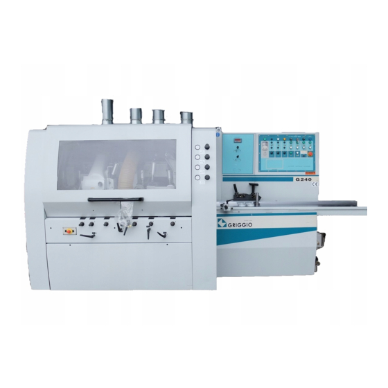
G 240 4/5/6/7
G 240 4/5/6/7
G 240 4/5/6/7
G 240 4/5/6/7
Via Ca' Brion, 40 – 35011
Tel. ++39 049 9299711
http://www.griggio.com
MOULDER
MOULDER
MOULDER
MOULDER
SPARE PARTS
SPARE PARTS
SPARE PARTS
SPARE PARTS
Reschigliano (PD) ITALY
Fax ++39 049 9201433
E-mail:info@griggio.com
Advertisement
Table of Contents

Related Manuals for GRIGGIO G 240 P4

Summary of Contents for GRIGGIO G 240 P4
- Page 1 SPARE PARTS SPARE PARTS SPARE PARTS INSTRUCTIONS INSTRUCTIONS INSTRUCTIONS INSTRUCTIONS 10/0 /0 /0 /09 9 9 9 GRIGGIO GRIGGIO GRIGGIO GRIGGIO Via Ca' Brion, 40 – 35011 Reschigliano (PD) ITALY Tel. ++39 049 9299711 Fax ++39 049 9201433 WOODWORKING MACHINERY...
-
Page 2: Table Of Contents
FEEDING DEVICE ADJUSTMENT ........18 UNLOADING AND POSITIONING ........3 CLEANING AND LUBRICATING........18 TECHNICAL DATA ..............4 BELT TENSIONING AND REPLACEMENT .......19 6.1. TECHNICAL FEATURES G 240 P4 ........4 MACHINE STARTING AND STOPPING......19 6.2. TECHNICAL FEATURES G 240 P5 ........5 FEEDING BY INVERTER ..........21 6.3. - Page 3 For a better understanding of this manual, attention should be paid to the symbols shown below Symbol Meaning When closing the safety cover, pay attention to your fingers Voltage inside! Danger! Electrical shock! Danger! Attention Open switchboard only Make sure that electrical and air supply are disconnected at the when main switch is in same time.
-
Page 4: Skilled Personnel
SKILLED PERSONNEL With qualified personnel are meant those persons who apply to the characteristics described in point C.2, chapter 7 " Advice For Use" IMPORTANT Read this instruction manual thoroughly before starting to set up the machine. Do not stop learning these concepts until you are working and do not allow unskilled or unsuitably trained people work with the machine. -
Page 5: Technical Data
Adjust the machine using adjusting screw (1); error tolerance is ± 0.1mm/m Anchor the machine to the floor by fitting expansion bolts in the holes in the support platforms. TECHNICAL DATA 6.1. TECHNICAL FEATURES G 240 P4 Technical Item Unit... -
Page 6: Technical Features G 240 P5
Technical Item Unit parameter Speed r min 6000 Planer shaft diameter Ø 40 Tools min/max diameter Ø 110 - Ø 200 Milling cutter max length upper horizontal planer shaft Max removal Vertical movement Horizontal movement Motor power kW (HP) 7.5 (10) Upper steel roller Ø... - Page 7 Technical Item Unit parameter Speed r min 6000 Planer shaft diameter Ø 40 shaft tools min/max Ø 125 - Ø 200 diameter shaft tools min/max Ø 110 - Ø 200 diameter 2nd and 3rd vertical planer shaft Milling cutter length Max removal Vertical movement Horizontal movement...
-
Page 8: Technical Features G 240 P5U
6.3. TECHNICAL FEATURES G 240 P5U N.B. FOR OTHER TECHNICAL SPECIFICATIONS, PLEASE SEE G 240 P5 Technical Item Unit parameter Speed r min 6000 Planer shaft diameter Ø 40 Tools min/max diameter Ø 110 - Ø 200 Milling cutter max length upper horizontal planer shaft Max removal Vertical movement... - Page 9 Technical Item Unit parameter Speed r min 6000 Planer shaft diameter Ø 40 shaft tools min/max Ø 125 - Ø 200 diameter shaft tools min/max Ø 110 - Ø 200 diameter 2nd and 3rd vertical planer shaft Milling cutter length Max removal Vertical movement Horizontal movement...
-
Page 10: Technical Features G 240 P 6U
6.5. TECHNICAL FEATURES G 240 P 6U N.B. FOR OTHER TECHNICAL SPECIFICATIONS, PLEASE SEE G 240 P6 Technical Item Unit parameter Speed r min 6000 Planer shaft diameter Ø 40 Tools min/max diameter Ø 110 - Ø 200 Milling cutter max length universal planer shaft Max removal Vertical movement... - Page 11 Technical Item Unit parameter Speed r min 6000 Planer shaft diameter Ø 40 shaft tools min/max diameter Ø 125 - Ø 200 shaft tools min/max diameter Ø 110 - Ø 200 2nd and 3rd vertical planer shaft Milling cutter length Max removal Vertical movement Horizontal movement...
-
Page 12: Electrical Connection
6.7. ELECTRICAL CONNECTION The connection of the machine to the main power must be carried out by a skilled electrician in accordance with the specifications of the standards in force. Turn the main switch to "0". Ensure that the main power line is not under tension before starting to connect the machine. The manufacturer of the machine is not responsible for general protection against short circuit. -
Page 13: Dust Production
DUST PRODUCTION In this type of machine the only material harmful for our health is sawdust. Dust production has been checked by Fachausschuß Holz and is clearly below the currently allowed limit value of 2 mg/m - DUST CHECK <mg/m OPERATING INSTRUCTIONS The Straightening-Profiling machine has to be used only by people trained for its safe utilization as well as for the right use of the protecting devices, and who perfectly know what kind of dangers exist while operating. -
Page 14: Safety Warnings
The operator needs to be informed of the noise levels the ordinary utilization of the machine generates, and of the factors affecting the exposure to the noise. These factors consist of: - right tool choice - right speed choice; - tool and machine maintenance; - type of material to be machined;... -
Page 15: Tool Assembly
10. TOOL ASSEMBLY Tools shall be manufactured in conformity with the European Standard pr EN 847-1. On tools to be used on machines with integrated feeding must be marked permanently and clearly with: - the manufacturer’s name or the trade-mark; - outside diameter x cutting length x hole diameter;... -
Page 16: Preplaner Table And Infeed Fence
11. PREPLANER TABLE AND INFEED FENCE - To adjust preplaner table (Fig. 7)(1), loosen handle (2) and adjust it on the straightening value of the lower edge, considering that the max. bending of the piece can be 10 mm. Reference "0" of the millimetre plate corresponds to the working table. - To adjust side fence (3) loosen handle (4) and adjust it on the desired straightening value of the vertical wall, still considering that the max. -
Page 17: Left-Hand Vertical Planer Shaft Adjustment (Third Shaft)
Horizontal adjustment Insert a spacer ring 10mm in thickness in the vertical shaft. (Fig. 13) Mount a rotary planer on the shaft with a known radius (example 62.5mm). (Fig. 11) To adjust the tools, place a gauge on the left-hand reference fence. Slacken the lock handle, adjust the planer shaft horizontally until the working edge of the milling cutter touches the gauge. -
Page 18: Second Lower Planer Shaft Adjustment
Infeed and outfeed presser adjustment. Adjust the vertical presser (2) located at the shaft inlet and position its end at approx. 3 mm from the milling cutter. (Fig. 14) The vertical presser (1), located at the shaft outlet, should be adjusted in different directions: horizontally, to bring the presser as close as possible to the milling cutter axially, to centre the presser with respect to the workpiece width vertically, using as reference a gauge or a workpiece, until the presser is perfectly aligned with the cutters. -
Page 19: Lower Roller Undertable Adjustment
19. LOWER ROLLER UNDERTABLE ADJUSTMENT The motor-powered lower roller must be vertically adjusted so that it protrudes by 0.05 mm max. with respect to the table. Vertical adjustment should be carried out by using the two screws located at the lower ends of the roller itself; lock by tightening the nuts. -
Page 20: Belt Tensioning And Replacement
Lubrication Standard lubricating Lubricated parts Lubricant Notes frequency volume Shaft bearings High temperature Once every six Belt tensioning lubricant (heat test Injection as defined month bearings higher than 120 ºC) Milling cutter spindle moving elements: chains, threaded Grease type CA ZG-3 Once a month Grease covered screws, bevel gears, etc,... - Page 21 Normal spindle start and stop To start the spindle automatically, press the corresponding 'START' buttons. For normal spindle stopping, press the corresponding 'STOP' button EMERGENCY STOP In a danger, the machine can be stopped by using the emergency mushroom buttons located at the working positions of introduction and extraction of the workpiece.
-
Page 22: Feeding By Inverter
24. FEEDING BY INVERTER WARNING: CHANGE SPEED ONLY WHEN THE MACHINE IS ON. - Feeding speed 0/30m/min is displayed on screen and can be changed by using the potentiometer after starting the movement by the corresponding button. - In order not to damage the inverter, wait approx. 10 seconds between turning the machine off and turning it back on (operation carried out from the main switch). -
Page 23: Main Panel Illumination
25.3. MAIN PANEL ILLUMINATION R U N R U N I N C H I N C H C LR TC - 501B TC - 501B TC - 501B TC - 501B TC - 501B TC - 501B TC - 501B TC - 501B Illumination: Normal situation:... -
Page 24: Current Value Setting
R U N R U N R U N R U N I N C H I N C H I N C H I N C H C LR C LR TC - 501A TC - 501A TC - 501A TC - 501A TC - 501A TC - 501A... -
Page 25: Clear Current Value
25.4.3. CLEAR CURRENT VALUE: Press “CLR/SET” key shortly to clear current value. Before press “CLR/SET” key, the main panel display is illuminated by the sketch map below. R U N R U N R U N R U N I N C H I N C H I N C H I N C H... -
Page 26: Reducing 0.01 To Current Value (Or Reducing Continuously)
25.4.5. REDUCING 0.01 TO CURRENT VALUE (OR REDUCING CONTINUOUSLY). Press “ “ key shortly to reduce 0.01 to current value. Keep on press - key to reduce to current value continuously, reducing 0.01 every 0.5 second. Before press “ ” key, the main panel display is illuminated by the sketch map below. R U N R U N R U N... -
Page 27: Reference Table For Parameters Setting
25.6. REFERENCE TABLE FOR PARAMETERS SETTING Formula: journey parameter = journey distance when motor rotate one circle (mm) ÷8x1000000. Setting 6 digits parameter, add zero in the front if number less than 6 digits. 25.7. MAXIMAL EXTERIOR SIZE AND INSTALLING SIZE... -
Page 28: Troubleshooting
26. TROUBLESHOOTING FAULT TROUBLESHOOTING FAULT REMEDY The display does not show Check whether the 220V or 110V AC Reconnect the correct electrical the numbers. electrical power supply voltage is voltage. normal. Check whether the fuse has blown or is Replace with a new 1A fuse. broken. -
Page 29: Problems With The Cutter
Problem Probable cause Cure a) The axial position of the a) Re-adjust the nip roller at the centre of The workpiece with feeding roller is not correct. the workpiece to be machined. respect to the b) Pressure exerted on the reference fence upper wall is not correct b) Make sure that all components exert a... -
Page 30: Electric Problems
27.2. ELECTRIC PROBLEMS Problem Probable cause Cure Machine does not No power supply or Check idle switch, emergency stop button and start insufficient voltage switch a) The emergency stop a) Press the emergency stop button button was pressed b) Cover was opened b) Close the cover c) Idle switch on control c) Press the idle switch...
Need help?
Do you have a question about the G 240 P4 and is the answer not in the manual?
Questions and answers