Table of Contents
Advertisement
Quick Links
Advertisement
Table of Contents

Subscribe to Our Youtube Channel
Related Manuals for DIGITALas DD-5000


Summary of Contents for DIGITALas DD-5000
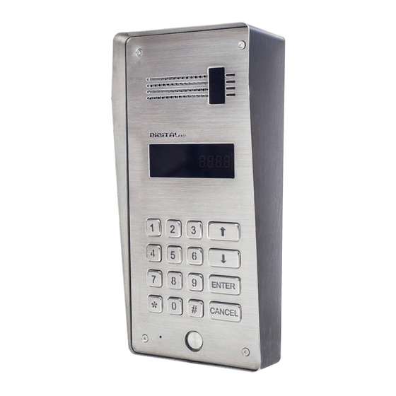
- Page 1 DD-5000 Digital Door phone DD-5000...
-
Page 2: Table Of Contents
Table of Contents 1 About DD-5000 door phone........................4 1.1 General features of the DD5000 Digital Door phone................4 2 Components of the System........................5 Keyboard lightening frame LF-1......................5 Keyboard lightening LH-1........................5 Roof to mount above plaster DR-1.......................5 Name frame NF-1..........................5 Power supply............................5 Electronic lock............................5... - Page 3 DD-5000 Entering from outside.........................15 Internal door unlock..........................16 6 Technical data............................17 7 Connection of DD-5000 door phone......................19 A standard wiring diagram.........................20 Keyboard/name frame lightening wiring diagram................21 Video camera wiring diagram......................21 Door phone connection to the network....................22 8 Error, its identification and troubleshooting....................24 User Manual..............................25...
-
Page 4: About Dd-5000 Door Phone
About DD-5000 door phone DD-5000 is a cutting age nowadays door phone of a high protection level and a modern design, intended for blocks of flats and could be used in an unfriendly environmental conditions. Door phone is created, considering the cutting age technical solutions. Outdoor station panel, system controller, commutator and other parts are integrated in one unit of a door phone, so less material is used for mounting the system and more time is saved. -
Page 5: Components Of The System
Roof to mount above plaster DR-1 Roof to mount above plaster is needed in order to arrange a door phone DD-5000 in the easiest way, avoiding insert into a plaster. Roof protects an appliance of direct sun rays and other environmental factors. -
Page 6: Mounting The System
Set mounting places of call module and other parts Choose System connection scheme (DD-5000 Connection) Design wire installation scheme and choose wires accordingly (DD-5000 Connection) Set System audio receiver physic and logic addresses (4.6. Setting of addresses) Install the System Switch the System power supply and begin programming works 8.1. -
Page 7: Dd-5000 Programming
DD-5000 DD-5000 programming Programming mode consists of 7 main MENU items. For programming mode menu structure see fig. 4.1. Menu items are placed in the order that the most frequently used settings could be reached the first. ( e.g. add / delete Tags). -
Page 8: Add A New Identificators
ENTER 4.2 Actions with codes Door phone DD-5000 does not contain door unlock codes generated and entered to memory in advance. Each user has a possibility to create and change his door unlock code, using user’s programming link (See User’s Manual. -
Page 9: Set/Change Users Door Unlock Code
DD-5000 [2.CodE] – action with codes [1.USEr] - set/change users door unlock code [2.SPin] - change Service PIN (SPIN) code [3.rESEt] - delete user’s door unlock codes Fig. 4.2.1 Structural scheme of code programming menu Set/change users door unlock code System administrator can enter a new or change an old user’s door unlock code. -
Page 10: Selection Of A Lock Type
Selection of a lock type Door phone DD-5000 allows to manage locks of two types ( Fig. 4.3.2): 1. NC – locks, connected to normally closed circuit, i.e. locks with a permanent power supply, paused only when unlocking (electromagnetic lock); 2. NO - locks, connected to normally opened circuit, i.e. -
Page 11: Volume Control
DD-5000 4.4 Volume control DD-5000 door phone allows to manage audio signal sound volume digitally. That means sound levels could be regulated any time easily without any additional tools. For Structural scheme of volume control menu see fig. 4.4.1. There are three types of setting a signal sound level: 1) indoor conversation volume 2) outdoor conversation volume 3) volume of system sound (buttons beep sound, door unlock sound etc.). -
Page 12: Disable A User According To Id
[5.USEr] – user administrating [1.diS.-onE] - disable a user according to ID [2.En.-onE] - enable a user according to ID [3.diS.-int.] - disable a group of users ID [4.En.-int.] - enable a group of users ID [5.oFF-Lc] - forbid to unlock a door using handset [6.on-Lc] - allow to unlock a door using audio receivers Fig. -
Page 13: Setting Of Addressing
DD-5000 4.6 Setting of addressing DD-5000 door phone system allows to use three types of addressing (fig. 4.6.1) - regular, shifted and hotel. The mentioned types are described in detail below. [6.AddrESSinG] – setting of addressing [1.rEGULAr] – regular addressing [2.ShiFtEd] –... -
Page 14: Reset To Factory Settings
For configuration a hotel addressing to the mentioned house perform the following steps: 1) Choose this type of addressing and start a new addressing configuration: [6.AddrESSinG] > > [3.hotEL] > > [2.rESEt] > > [rSt?] > > [donE] – An old ENTER ENTER ENTER... -
Page 15: How To Use A Door Phone
DD-5000 How to use a door phone Calling to a flat For connection with a subscriber enter his/her flat’s number (from 1 to 9999) and press (otherwise ENTER call will be started automatically after 3 sec). Should a mistake appear or for canceling your call press CANCEL Conversation session starts upon subscriber’s, whom you are calling to, answer. -
Page 16: Internal Door Unlock
User’s Manual, page 24. After entering a right code using a keyboard, the door unlocks. A note “OPEN” appears on a display with a sound signal of the door phone and an additional sound signal (informing on door unlock using individual code, related to the flat) will be sent to an audio receiver. •... -
Page 17: Technical Data
Three types of addressing: regular, shifted and hotel • Possibility to install a video camera * DD-5000T – door phone with TM reader, DD-5000R – door phone with TM and RFID readers ENTER CANCEL Fig. 6.1 Dimensions of DD-5000 door phone... - Page 18 Fig. 6.2 Dimensions of roof to mount above plaster DR-1 Fig. 6.3 Dimensions of Name frame NF-1...
-
Page 19: Connection Of Dd-5000 Door Phone
DD-5000 Connection of DD-5000 door phone See the door phone module commutation connectors of a door phone on the figure above. Description of the mentioned connectors is presented in Table 7.1; selecting of electric installation wire upon the length is presented in Table 7.2... -
Page 20: A Standard Wiring Diagram
A standard wiring diagram A minimal standard DD-5000 door phone completion involves: • Door phone module DD-5000 • Stabilized power supply (12V, 1.5 A) • Electronic lock • Door unlock button • Door phone handsets Video GND 12V Speaker Lightening... -
Page 21: Keyboard/Name Frame Lightening Wiring Diagram
DD-5000 Keyboard/name frame lightening wiring diagram Keyboard lightening frame is attached to J3 (lightening) connector. If name frame is complemented with a door phone, frame lightening switches together with keyboard. Name frame Keyboard lightening lightening (12 V) frame (12 V) -
Page 22: Door Phone Connection To The Network
DD-5000 is mounted for each entrance with a general connection to one commutator. See fig. 7.4 for wiring diagram for two DD-5000 call modules. See fig. 7.5 for wiring diagram for five DD-5000 call modules. - Page 23 DD-5000 Fig. 7.5 Wiring diagram for five DD-5000 call modules NOTE: • All system units – door phone modules and commutators - should be supplied from the separate power supply • In network system audio handsets connected to commutator outlet •...
-
Page 24: Error, Its Identification And Troubleshooting
Error, its identification and troubleshooting Door phone DD-5000 graphically indicates the main errors. Graphical codes and descriptions of errors, fixed by a door phone are presented in table 6.1. In case of Er2-Er5 errors, doors have been unlocked every 5 minutes automatically. -
Page 25: User Manual
DD-5000 User Manual NOTE. Each flat is delivered with an appropriate manufacturer PIN code – 1234. Change it, otherwise doors unlock code and new identificator programming function are unavailable. 1. How to use a door phone: For connection with a subscriber enter his/her flat number (from 1 to 9999) and press ENTER (otherwise call will be started automatically after 3 sec). -
Page 26: Notes
Notes:... - Page 27 DD-5000...
- Page 28 DIGITALas, JSC Kestucio str. 62A, Vilnius, LT08112 Tel :+370 5 2336619 info@digitalas.lt www.digitalas.eu...
Need help?
Do you have a question about the DD-5000 and is the answer not in the manual?
Questions and answers