Table of Contents
Advertisement
Quick Links
Advertisement
Table of Contents

Related Manuals for rayence 1417WGC

Summary of Contents for rayence 1417WGC
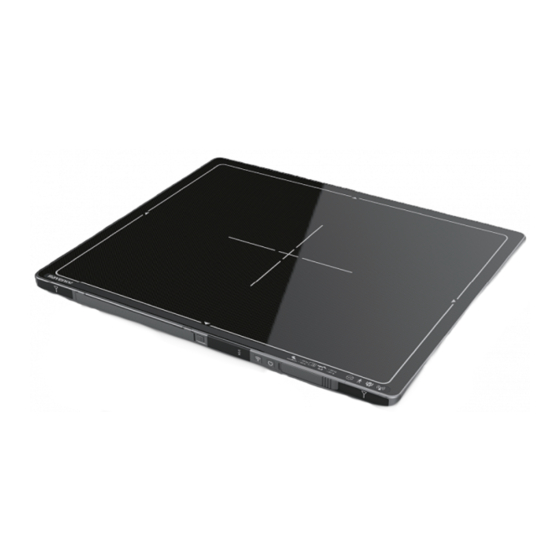
- Page 1 Version 1 Date: 2014-03-24 1417WGC User / Installation Manual R-USM-020...
- Page 2 © Copyright 2014, Rayence Co. Ltd. All pages of this document contain proprietary and confidential information of Rayence Corporation and are intended for exclusive use by Rayence Corporation personnel or customers. Copying, disclosure to others or other use is prohibited without the express written authorization from Rayence Corporation.
- Page 3 Attention For improvement of product performance, supplementation, or follow-up of information; the contents of this manual are subject to change without separate prior notice. Please note that our company has neither responsibility for any accidents nor obligation to do free repair service for any damage of the equipment due to user's mistake, which resulted from failure to follow the contents in this manual.
-
Page 4: Table Of Contents
Contents Introduction ................. 6 Overview ..................6 Intended use ................6 Product features ................ 7 Product components ..............8 Components Description ............11 Warning ..................14 Caution ................... 16 Notes for Using the Detector ............. 19 Preparing ................. 19 Handling................... 21 Before Exposure .............. - Page 5 (1) Maintenance ................77 (2) Cleaning ................... 77 (3) Inspection ................78 (4) Disposal or Recycling ............. 79 (5) Marking and labeling symbols ..........80 Appendix ................... 82 R-USM-020...
-
Page 6: Introduction
1. Introduction (1) Overview The 1417WGC is a wireless digital X-ray flat panel detector that can generate images of any part of the body. The wireless LAN((IEEE 802.11a/g/n) communication feature improves the operability, and high-speed processing. This X-ray imaging system consists of a scintillator directly coupled to an a-Si TFT sensor. -
Page 7: Product Features
(3) Product features Wi-Fi (802.11a/g/n) Based on a-Si TFT active matrix Compact (15.4mm thickness) and light weight (Typ. 3kg) Limiting Resolution : 3.9 lp/mm 14/16-bit digital output Easy integration R-USM-020... -
Page 8: Product Components
(4) Product components Medical Image Processing Unit Photo Item Part Name Quantity Detector RD1417WGC Battery pack RB37WHA Battery charger RC120WA Charger PMP120-13-3 adapter RA001A Power supply RP003A R-USM-020... - Page 9 Cables Item Part Name Length Quantity Link cable Interface VRH017A cable cable(A to VRH078A 1.8m VRH027A cable AC Power VRH018A/019A 1.8m cord Installation CD o Manual o Detector Library R-USM-020...
- Page 10 Option o Additional Battery o Trigger cable R-USM-020...
-
Page 11: Components Description
It supports 2T2R (2 transmit 2 receive) MIMO technology, which delivers throughput up to 300Mbps. 1417WGC in the RF module does not use DFS band. *RF module (FCC ID: PPD-AR5BHB116) 2. Battery unlock-lever : This is an unlock-lever to remove battery. - Page 12 (2) Battery & Charger 1. Battery : Lithium ion battery. The number of times being acquired image is 960 images(@ cycle time : 15s). The batteries are rechargeable The charging time = 3 hours. 2. Charger : Two port cradle type. 3.
- Page 13 (4) Power supply box 1. Power plug connector: Connect with AC power supply cord 2. LAN connector : Ethernet port for transmitting the image/command between detector and PC 3. Link cable connector: Power connector for detector operating 4. LED indicator: Four LEDs to display the status ※...
-
Page 14: Warning
(6) Warning Make sure to observe Environment of Use and Storage the following right Follow the specified process of operational instructions written in this manual for the safety of the users and patients. Does not use or store the instrument near any flammable chemicals such as thinner, benzene, etc. - Page 15 When Problem Occurs Should any of the following occur, immediately turn OFF the power of each instruments, unplug the power supply cord from the AC outlet, and contact Rayence representative or distributor. When there is smoke, odd smell or abnormal sound.
-
Page 16: Caution
(7) Caution Environment of Use and Storage Do not install the instrument in a location with the conditions listed below. Otherwise, it may result in failure or malfunction, cause fire or injury. Close to facilities where water is used. ... - Page 17 If the detector and/or battery get wet, have them checked by your service provider or contact Rayence, even if they appear to be working properly. R-USM-020...
- Page 18 Use of a non-Rayence-approved battery or charger may present a risk of fire, explosion, leakage, or other hazard. Rayence's warranty does not cover damage to the detector caused by non-Rayence-approved batteries and/or chargers Misuse or use of incompatible batteries and charging...
-
Page 19: Notes For Using The Detector
2. Notes for Using the Detector (1) Preparing Fully charge the battery pack. Charge the battery on the day of examination or on the previous day. Battery slowly discharges even of not in use. The battery pack may have expired if it discharges immediately after being fully charged. - Page 20 <Remove battery> R-USM-020...
-
Page 21: Handling
(2) Handling Handle the instrument carefully, as it may be damaged if something is hit against it, dropped, or receives a strong jolt. R-USM-020... -
Page 22: Before Exposure
(3) Before Exposure Be sure to check the equipment daily and confirm that it works properly. Sudden heating of the room in cold areas will cause condensation to form on the instrument. In this case, wait until condensation disappears before performing exposure. ... -
Page 23: Limit Of Load
(5) Limit of Load Uniform load: 150 kg over the whole area of sensor window. Local load: 100 kg on an area 40 mm in diameter. Be sure to use the sensor unit on a flat place so it will not bend. Otherwise, the sensor may be damaged. -
Page 24: Disinfection And Cleaning
(6) Disinfection and Cleaning Do not spray the detector directly with disinfectants or detergents. Do not use anything other than neutral detergent for cleaning the cover of the instrument. Otherwise, the coating will be corroded. (7) Others Be sure to reconnect the cables to the proper connectors. Otherwise, the instrument may malfunction or may be damaged. -
Page 25: Technical Features
3. Technical Features (1) Mechanical Features Size 460 x 384 x 15.4 mm Weight 3 kg Encapsulation Material Carbon fiber plate with 1.8 mm thickness Window Material Carbon fiber plate with 1.8 mm thickness (2) Electrical Features Detector Sensor Type Amorphous Silicon with TFT (Single Panel) X-ray Converter S:Tb... - Page 26 Power Supply Size 188 x 92 x 41.5 mm Weight 0.46kg Input 110~220VAC (50/60Hz) Output Typ. 24VDC (Max 1.9A) Battery Size 263.2 x 127.8 x 6 mm Weight Typ. 0.3 kg Input 12.5 VDC Output 11.1 VDC Charging time Typ. 3 hours Capacity Typ.
- Page 27 Adapter Size 160 x 76 x 43.7mm (cable length: 1.28m) Weight Typ. 0.73 kg Input 100~240 VAC, 47~63 Hz, 1.4~0.6A Output 20 VDC, Max 6.0A R-USM-020...
- Page 28 Wireless Spec 802.11a/g/n compliance Standard Without DFS (5.25GH to 5.35GHz and 5.47 to 5.725) Band Peak Rate 300Mbps Frequency 2.4 GHz / 5 GHz Bandwidth 20MHz/40MHz MIMO ※ Recommended Maximum operable distance : 10m (From the Access Point) ※ 5150~5250 MHz band is restricted to indoor operations only.
-
Page 29: Environmental Requirement
(3) Environmental requirement Item Min. Typ. Max. Unit Note Temperature ℃ (Storage) Temperature ℃ (Operation) Humidity (Storage) H.R. Humidity (Operation) H.R. 10-150Hz, Vibrations 10Sweeps, (Wrapping (8G) 1min/Octave, condition) XYZ axis ※ Regularly changed parts : Battery (warranty 6 months) (4) PC Requirements Processor: At least Intel Pentium IV HT with 2.8GHz, Intel ... -
Page 30: Installation
4. Installation The Detector is composed of sensitive electronic parts and components. It is recommended to use the product in a clean Portable place and to exercise caution to ensure that it is not affected by Imaging processing dust or liquids. It is recommended to Use a dry and soft cloth to unit must be clean the detector housing. -
Page 31: Connection (Manual Trigger)
A. Connect the battery pack or power cable to the equipment. * In wired mode, the frame ground is necessary. B. Connect the USB cable from your PC to AGI. ※ Be sure to sure only the dedicated battery pack, RB37WH for 1417WGC. Wireless Communication R-USM-020... - Page 32 A. AP Router(Line sharer) setting - SSID : Griffon - Internal network - IP address : 2.2.2.1 - Subnet mask : 255.255.255.0 - Dynamic IP allocation range : 2.2.2.2~2.2.2.254 - Pre-Shared Key(Password) : project302 - Authentication methods : WPAPSK or WPA2PSK - Password methods : TKIP/AES - AP IP : 2.2.2.1 - Channel (Frequency)
- Page 33 - After wireless connection is established, perform ‘Get Bright’ in ‘Calibration’ tap. - Check the value named ‘Wireless Signal’ in black log screen. Wireless Signal = Link Quality (Max. 100) - Check the value named ‘Battery Remain’ in black log screen. Battery Remain = Battery Remain(Max.
- Page 34 Software Setting Figure 2: Davinci Setting R-USM-020...
- Page 35 Trigger Connection A. Connect the P-interface cable or trigger cable to the generator X-ray Generator Connection Make A. Mode 1 : P-interface cable mode assurance doubly sure SIGNAL RATING Connect the P-interface cable between the AGI box and X-ray before connection. generator.
- Page 36 The window time can be changed. Refer to the following pictures Exposure Time(*clk) 4999999 is designate to 0.5sec R-USM-020...
- Page 37 B. Mode 2 : Trigger cable mode Make assurance Connect the Trigger cable between the X-ray enable connector of doubly sure SIGNAL RATING AGI with X-ray generator. before connection. Figure 8: <2nd example> wiring for the interface between portable generator & detector Connection description Signal New Label...
- Page 38 Operating description Figure 3 : Timing chart t1: It will be occurred when exposure switch is pushed completely after. t2: Window time of detector is varying 0 sec ~ 5 sec. which can be control by S/W. (Editing parameter: Exposure Time – Refer to the NOTE) ...
-
Page 39: Connection (Auto Trigger)
(3) Connection (Auto Trigger) Power Connection A. Connect the battery pack or power cable to the equipment. * In wired mode, the frame ground is necessary. ※ Be sure to sure only the dedicated battery pack, RB37WH for 1417WGC. R-USM-020... - Page 40 Wireless Communication A. AP Router(Line sharer) setting - SSID : Griffon - Internal network - IP address : 2.2.2.1 - Subnet mask : 255.255.255.0 - Dynamic IP allocation range : 2.2.2.2~2.2.2.254 - Pre-Shared Key(Password) : project302 - Authentication methods : WPAPSK or WPA2PSK - Password methods : TKIP/AES - AP IP : 2.2.2.1 - Channel (Frequency)
- Page 41 C. Checking Link Quality & Battery Remain - After wireless connection is established, perform ‘Get Bright’ in ‘Calibration’ tap. - Check the value named ‘Wireless Signal’ in black log screen. Wireless Signal = Link Quality (Max. 100) - Check the value named ‘Battery Remain’ in black log screen. Battery Remain = Battery Remain(Max.
- Page 42 Software Setting Figure 4: Davinci Setting R-USM-020...
- Page 43 Important Note In AUTO TRIGGER MODE, the trigger will be forced not to acquire images when detector senses vibration or shock. In READY mode, Detector will automatically switch to WAIT mode when detector senses vibration or shock, so that user won’t acquire images in WAIT mode although X-ray exposure applies.
-
Page 44: Ip Set Up
(5) IP set up [My Network Places] → [Properties] → [Local Area Connection] → [Properties] → [Internet Protocol (TCP/IP)] → [Use the following IP address] IP address: Obtain an IP address automatically IP address : Obtain an IP address automatically R-USM-020... -
Page 45: Using Fpd_Manager (Ip, Ssid Change / Upgrade Fw)
(6) Using FPD_Manager (IP, SSID Change / Upgrade FW) Change IP Address of Detector A. Turn on Detector and connect to PC (wired connection is recommended) B. After detector boot up, Launch FPD_Manager.exe R-USM-020... - Page 46 C. Check the “IP Change” and type current IP address as below D. Type IP address to set R-USM-020...
- Page 47 E. Click “Start Setting” button F. Restart detector(Turn Off then On) Change SSID and PSK(Pre-Shared Key) A. Turn on Detector and connect to PC (wired connection is recommended) B. After detector boot up, Launch FPD_Manager.exe R-USM-020...
- Page 48 C. Check the “SSID change” and write current IP address as below D. Type SSID and PSK to set R-USM-020...
- Page 49 E. Click “Start Setting” button F. Restart detector(Turn Off then On) Upgrade Firmware A. Turn on Detector and connect to PC (wired connection is recommended) B. After detector boot up, Launch FPD_Manager.exe R-USM-020...
- Page 50 C. Check the “SSID change” and write current IP address as below D. Select firmware or FPGA file by click “select” button. Click “Start Setting” button E. Restart detector(Turn Off then On) R-USM-020...
-
Page 51: Calibration
5. Calibration (1) General Principle X-ray detector Notation should be used at stable state Calibration can be done by image acquisition S/W. The gain- within driving offset correction (under calibration) will be done with one dark, at temperature range. Acquire the X-ray least one bright and object frame. - Page 52 Bright Calibration Point calibration To gain correction, bright frame and dark frame should be range of acquired. The dark frame is needed only one frame. The bright bright is can be frame is recommended to be acquired more than 2 different select by which exposure level is levels of median values of bright frames.
-
Page 53: Calibration
(2) Calibration Describe the calibration step by step. 1st Step Click on the “Get Dark” button. The acquired dark frame “dark.raw” will be generated in the “\cal\” folder. Figure 5: Get dark R-USM-020... - Page 54 2nd Step Click button [Get Push “Get Bright” button at different four of X-ray condition. The Bright]. It will produce frame X-ray condition should be set or tested before, same as the level with name %CAL% of ‘1.2’. Push “Get Bright” button at least 2 times at same xNNNNNA.raw condition, and then the offset subtracted bright (gain) is where...
- Page 55 3rd step After 2 step, the “Generate” button will be activated. Click the button “Generate”, and then calibration point will be generated which of file name is “A ‘# of point’_ ‘median value of generated point’” like file of bright frame. The acquired bright frames within tolerance value which is variance of median level of acquired bright frames will be averaged and generated to a calibration point.
- Page 56 4th step After 3rd step, Change Bad Pixels Removal Tab, Click the button “Generate Auto BPM”, and then Defect Map will be generated which of file name is “BPM.raw “ at the “\cal\” folder. Figure 8: Bad pixels removal R-USM-020...
- Page 57 5th step For additional Defect correction, if “BPMM.raw” is existed at the install CD, copy to the “\cal\” folder. 6th step On Acquisition Tab. Check the box “Offset Calibration”, “Gain Calibration”, “Bad Pix Map” for activate to each calibration and Bad Pixels Removal.
-
Page 58: Image Acquisition Test
6. Image Acquisition Test (1) Get Image On Acquisition tab, click the “Get Image” button to get image. After click the button, you can see pop-up window, which is display window time and process of acquiring image. R-USM-020... -
Page 59: View Images
(2) View Images Frame- and image-files have extension “raw” and contain pixel data in signed 16-bits little-endian format. One could view those files in Photoshop or another image editor. R-USM-020... - Page 60 Common controls and displayed statistics Pixel_Min – minimum pixel value in frame- or image- data Pixel_Max – maximum pixel value Pixel_Black – if a pixel ≤ Pixel_Black then it is displayed as black (RGB 0, 0, 0) ...
- Page 61 Histogram’s presentation Relative Histogram Scale [H]=1000 means that that the distance depicted as “H” on the drawing matches 1% of total number of pixels. Respectively [H]=100 means that “H” matches 0.1% of pixels and [H]=500 means that “H” matches 0.5% of pixels. R-USM-020...
- Page 62 Marker type “S” Displays local surround of selected location Marker type “R” Display profile chart of a row. R-USM-020...
- Page 63 Marker type “C” Display profile chart of a column. R-USM-020...
-
Page 64: Get Recent Frame
(3) Get Recent Frame If the image is not transferred to the PC after exposure because of connection fail (wire or wireless). You can get a recent frame again. R-USM-020... -
Page 65: Operation
7. Operation (1) Recommend X-ray detector should be used at stable state within driving temperature range. Acquire the X-ray images after power on and 5 minutes warming up to obtain high quality images. The calibration should be performed every 6 months (2) Switching power on / off All connection should be done, before turn on the power. -
Page 66: Safety Information
8. Safety Information (1) Safety standard Do not This equipment has been tested and found to comply with the touch signal limits for medical devices in IEC 60601-1-2:1994. These limits input, signal output are designed to provide reasonable protection against harmful or other connectors, and the patient interference in a typical medical installation. - Page 67 Type of protection against electric shock: Class I equipment Classification according to the degree of protection against ingress of water as detailed in the current edition of IEC 529: IPX0, ordinary equipment This equipment is not suitable for use in the presence of ...
-
Page 68: Electromagnetic Compatibility Information
(2) Electromagnetic Compatibility Information Guidance and manufacturer’s declaration - electromagnetic emissions The EUT is intended for use in the electromagnetic environment specified below. The customer or the user of the EUT should assure that it is used in such an environment. Immunity Test Compliance Electromagnetic Environment - Guidance... - Page 69 Guidance and manufacturer’s declaration - electromagnetic immunity The EUT is intended for use in the electromagnetic environment specified below. The customer or the user of the EUT should assure that it is used in such an environment. The EUT is intended for use in the electromagnetic environment specified below. The customer or the user of the EUT should assure that it is used in such an environment.
- Page 70 Guidance and manufacturer’s declaration - electromagnetic immunity The EUT is intended for use in the electromagnetic environment specified below. The customer or the user of the EUT should assure that it is used in such an environment. Immunity test Compliance Electromagnetic environment - guidance 60601-1-2 level...
- Page 71 Recommended separation distances between portable mobile communications equipment and the EUT There is intended for use in an electromagnetic environment in which radiated RF disturbances are controlled. The customer or the user of the EUT can help Prevent electromagnetic interference by maintaining a minimum distance between portable and mobile RF communications equipment (transmitters) and the EUT as recommended below, according to the maximum output power of the communications equipment.
- Page 72 Immunity and Compliance Level Immunity test IEC 60601-1-2 Actual Immunity Level Compliance Level Test Level Conducted RF 3Vrms 3Vrms 3Vrms IEC 61000-4-6 150kHz to 80MHz Radiated RF 3Vrms 3V/m 3V/m IEC 61000-4-3 80MHz to 2.5GHz Guidance and manufacturer’s declaration - electromagnetic immunity The EUT is intended for use in the electromagnetic environment specified below.
-
Page 73: Radio Frequency Compliance
9. Radio Frequency compliance (1) FCC Notice (U.S.A) Test standards - 47CFR Part 15.107 (b) / 47CFR Part 15.109 (g) Class A. FCC Part 15 C Section 15.247, Operation within the bands 902–928 MHz, 2400–2483.5 MHz, and 5725–5850 MHz - FCC Part 15 C Section 15.407, Operation within the bands 902–928 MHz, 2400–2483.5 MHz, and 5725–5850 MHz ... - Page 74 FCC CAUTION Changes or modifications not expressly approved by the party responsible for compliance could void the user’s authority to operate the equipment. This transmitter must not be co-located or operated in conjunction with any other antenna or transmitter. When installing it in a mobile equipment This equipment complies with FCC radiation exposure limits set forth for an uncontrolled environment and meets the FCC radio frequency (RF) Exposure Guidelines in Supplement C to OET65.
-
Page 75: Ic Notice (Canada)
(2) IC Notice (CANADA) Test standards - ICES-003 Issue 4 - IC RSS-210 Issue 7, Operation within the bands 902–928MHz, 2400–2483.5 MHz, and 5725–5850 MHz - IC RSS-210 Issue 7, Operation within the bands 902–928 MHz, 2400–2483.5 MHz, and 5725–5850 MHz ... -
Page 76: R&Tte Notice (European Union)
(3) R&TTE Notice (European Union) Test standards - EN 62311 - ETSI EN 301 489-1 - ETSI EN 301 489-17 - ETSI EN 300 328 - ETSI EN 301 893 R-USM-020... -
Page 77: Maintenance
Maintenance (1) Maintenance Maintenance of the detector should be done by an authorized service provider safety reasons, be If the Detector Panel is defective, the detector will be sure to turn OFF the returned as is to the manufacturer for repair power of the detector when the Clean the equipment with a dry soft cloth, or a soft cloth... -
Page 78: Inspection
If problem still cannot be corrected, please contact Rayence representative or distributor. It is recommended that a record of the inspection be kept by making copies of the check lists in this section, or making a separate check list. -
Page 79: Disposal Or Recycling
(4) Disposal or Recycling Follow local governing ordinances and recycling plans regarding the disposal or recycling of device components. Disposal of old Electrical & Electronic Equipment (Application in the European Union and other European countries with separate collection system.) This symbol indicates that this product shall not be treated as household waste. -
Page 80: Marking And Labeling Symbols
(5) Marking and labeling symbols Symbols Meaning Caution : “Attention, see instructions for use” Alternate current Protective earth (Ground) Off (power : disconnect from the main switch) On (power : connect to the main switch) Warning Caution Note Manufacturer Date of manufacture Serial number TYPE B Equipment R-USM-020... - Page 81 WEEE : Waste Electrical and Electronic Equipment Authorized representative in the European Community CE symbol grants the product compliance to the European Directive for Medical Devices class Ⅱb 93/42/EEC as a device 1999/5/EC. Authorized by Notified Body SGS (code no.:0120) of British Recognized Component Mark for Canada and the United States non-ionizing radiation...
-
Page 82: Appendix
Appendix Dimension [unit : mm] R-USM-020... - Page 83 Rayence Co., Ltd. 14, Samsung 1-ro 1-gil, Hwaseong-si, Gyeonggi-do, Korea www.rayence.com Rayence Co., Ltd. 14, Samsung 1-ro 1-gil, Hwaseong-si, Gyeonggi-do, Korea R-USM-020 www.rayence.com...
Need help?
Do you have a question about the 1417WGC and is the answer not in the manual?
Questions and answers