Advertisement
AUTOMATIC TIMER FLUSH VALVE (ATF2)
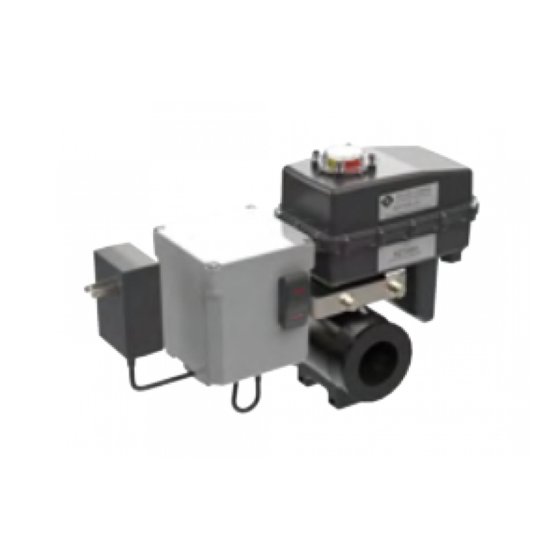
Description: The ATF2 is an automated flush valve that is designed for use with the "Thompson" Strainer. The ATF2 has a digital
timer that allows the operator to set the frequency and duration of valve opening in order to allow more effective and efficient flushing
of the collected debris from the strainer.
Control Box: The digital timer is located inside a NEMA 4 enclosure that includes an Auto and Manual Valve function switch.
Ball Valve/Actuator: The valve body has a 316SS ball inside a UV modified, glass-filled Nylon housing. The actuator has high torque
motor gears and solid state components for increased durability and maintenance free performance contained inside a NEMA6P
enclosure.
Primary Components:
A
POWER SUPPLY
CONTROL TOGGLE SWITCH,
B
3-POSITION, LIGHTED
C
CONTROL BOX
D
ACTUATOR HOUSING
E
POWER CORD CLIP
F
POWER SUPPLY JACK
G
ACTUATOR CABLE
DIGITAL TIMER
H
(inside control box)
I
VALVE HOUSING
J
STAINLESS STEEL BALL
K
CONTROL BOX CABLE
VALVE POSITION INDICATOR,
L
LIGHTED
M
INLET PORT
N
OUTLET PORT
SIDE VIEW
A
E
F
G
H
TOP VIEW
1 of 5
B
C
M
N
D
I
J
K
L
Advertisement
Table of Contents

Related Manuals for Miller-Leaman THOMSON ATF2

Summary of Contents for Miller-Leaman THOMSON ATF2
- Page 1 AUTOMATIC TIMER FLUSH VALVE (ATF2) Description: The ATF2 is an automated flush valve that is designed for use with the “Thompson” Strainer. The ATF2 has a digital timer that allows the operator to set the frequency and duration of valve opening in order to allow more effective and efficient flushing of the collected debris from the strainer.
-
Page 2: Installation
Optional Power Input If used in conjunction with the Miller-Leaman Pressure Differential Alarm (PDA or PDA2) package you have the option to power the ATF2 by connecting a ML10808 Twisted Cable Power Connector from the Power Port Jack on the PDA/PDA2 control box to the Power Supply Jack on the bottom of the ATF2 Control Box. -
Page 3: Additional Functions
AUTOMATIC PROGRAMMING INSTRUCTIONS Preparation for Use Check that the ATF2 has power, the Valve Position Indicator is glowing red (Closed) and the Control Switch is in the OFF position. Check that the valve is operational by momentarily pressing the MANUAL FLUSH end of the Control Switch. A red indicator light on the lower part of the switch will be visible and the valve will open. - Page 4 DIGITAL TIMER BUTTON AND DISPLAY INFORMATION T1/T2 operation indicator Elapsed Time Display T1/T2 setting value indicator Set Time Display Output indicator Lock indicator RESET Button SET/LOCK Button SYMBOL FLUSH FACTORY SETTING UP / DOWN DIGIT Button FREQUENCY 24:00 DURATION DISPLAY DISPLAY VALVE CLOSED VALVE OPEN...
-
Page 5: Power Supply Specification
ATF2 MODEL INFORMATION MODEL NUMBER NPT PIPE SIZE VALVE BALL/BODY MAXIMUM PRESSURE ATF2-075 3/4” 316SS / Nylon 150 PSI @ 70 deg. F ATF2-100 1" 316SS / Nylon 150 PSI @ 70 deg. F ATF2-150 1-1/2" 316SS / Nylon 150 PSI @ 70 deg. F ATF2-200 2"...
Need help?
Do you have a question about the THOMSON ATF2 and is the answer not in the manual?
Questions and answers