Table of Contents
Advertisement
Quick Links
SPECIFICATIONS
MODEL NUMBER .................................................... RC2800PRKX1SU
POWER REQUIREMENTS. ..................................... 97-240 VAC @ 12A
ENCLOSURE SIZE .................................................. W=19" / H=5.25" / D=10"
COLOR ..................................................................... Black Anodized
POINTING ACCURACY ........................................... <0.1°
READOUT ACCURACY ........................................... <0.3°
MINIMUM COMMANDED MOTION ......................... >0.25°
DIGIT SIZE ............................................................... 0.5" Heading / .375" Mode / Speed
CONTROL SWITCHES ............................................ Tactile 0.5" Diameter
MICROPROCESSOR TYPE .................................... "Microchip" PIC18F2520-I/SP
CONTROLS .............................................................. Power Switch, ON / OFF
MODES..................................................................... (3) Operational Run Modes / (10) Presets
STANDARD OUTPUT VOLTAGE ............................ POL 48VDC 6.7A
COMPUTER INTERFACE ........................................ RS232 Port
FEATURES
The M2 RC2800PRKX1SU is our Mid Grade rack-mount controller. The RC2800PRKX1SU was developed for "Commercial Grade"
Polarity Pedestal Models.
The M2 RC2800PRKX1SU uses a Microchip PIC18F2520-I/SP for Micro processing user commands, M2 software and EEprom for
memory. User modes include: (3) Operational / Run Modes and (10) programmable presets.
The M2 RC2800PRKX1SU uses PWM (Pulse Width Modulation) for speed control, allowing for full torque at the slowest input
speed. Location heading from the motor assembly is supplied via an Open Loop Circuit to the controllers' microprocessor.
The M2 RC2800PRKX1SU software also includes a full GUI software for setup and run modes and a Interface Control Document
(ICD) is supplied with the RC2800PRKX1SU.
Computer interface to the RC2800PRKX1SU is via an RS232 port.
M2 Antenna Systems, Inc. 4402 N. Selland Ave. Fresno, CA 93722
Tel: (559) 432-8873 Fax: (559) 432-3059 Web: www.m2inc.com
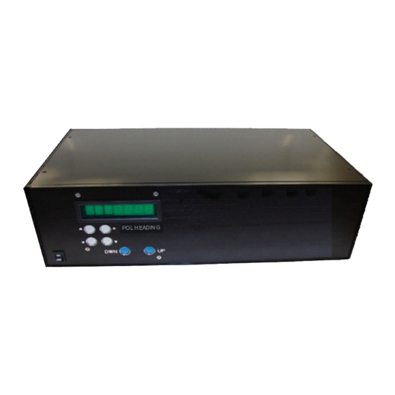
M2 Antenna Systems, Inc.
Model No: RC2800PRKX1SU
SINGLE AXIS CONTROLLER
Speed Buttons, Increments 1-9
Clockwise & Counterclockwise Buttons
Up & Down Mode Buttons
©2022 M2 Antenna Systems Incorporated
6.09.22
Rev.01
Advertisement
Table of Contents
Troubleshooting

Subscribe to Our Youtube Channel
Related Manuals for M2 Antenna Systems RC2800PRKX1SU

Summary of Contents for M2 Antenna Systems RC2800PRKX1SU
- Page 1 Location heading from the motor assembly is supplied via an Open Loop Circuit to the controllers’ microprocessor. The M2 RC2800PRKX1SU software also includes a full GUI software for setup and run modes and a Interface Control Document (ICD) is supplied with the RC2800PRKX1SU.
- Page 2 RC2800PRKX1SU PARTS & HARDWARE DESCRIPTION RC2800PRKX1SU, SINGLE AXIS CONTROLLER ........1 ENCLOSER HANDLES AND HARDWARE ..........2 POWER CORD, 120VAC 10A ..............1 RUBBER FEET .................... 4 FUSE, 5 AMP 250V ..................5...
-
Page 3: Mode Buttons
FRONT PANEL CONTROL OVERVIEW Digital Display Mode Buttons Speed Buttons Power Switch Control Buttons ON/OFF (POWER) This button controls AC power to the control unit. DIGITAL DISPLAY & DIGITS #1: (full left) shows the selected MODE for operation or programming. #2: Indicates the Positioner travel SPEED in relative numbers from 0 to 9. -
Page 4: Rear Panel Overview
RC2800PRKX2SUMC UNITS WITH HEATER: If your RC2800PRKX1SU control unit has the add on power supply, please see wiring designations on Terminals 6 & 7. The Heater power supply is powered on at all times. *Note, the heater is thermostatically controlled. -
Page 5: Run Modes
BASIC OPERATIONS / RUN MODE DESCRIPTIONS RUN MODES: Modes 0, 1 and 2 are all run modes capable of activating the positioner in both the CCW / DWN and CW / UP direction. MODE 0 = MANUAL OPERATION MODE: Pushing the CCW button activates the positioner in the Counter Clockwise direction, and the Heading count will go down. - Page 6 M2 SETUP UTILITY INSTALLATION & OVERVIEW MINIMUM COMPUTER REQUIREMENTS AND HARDWARE: 500 MHz Intel Pentium II or equivalent Computer (Preferably a Laptop) 256 MB of RAM / 1MB of Disk Space Windows 98 / XP / Straight through DB9 RS232 Serial Cable INSTALLING THE M2 SETUP UTILITY SOFTWARE: In most cases the controller will be pre-configured at the factory.
- Page 7 M2 SETUP UTILITY OVERVIEW CONTINUED... New Heading: Change or type the desired heading value and click on “Go.” The “Stop” command will immediately stop the current motion. Change ID: Changes the ID Byte as stored in the controller. This can be used to identify a specific controller board and controller based upon your usage.
- Page 8 AZIMUTH SYSTEM CONFIGURATION Each Axis of the RC2800PRKX3SU needs to be configured for a spectrum of use and position of limits. The programmable limits in the RC2800PRKX3SU control, give the ability to specify the amount of travel around a spectrum of use. The AZ/EL/POL 3 axis positioner has physical limits CCW / DWN and CW / UP. The limits provide physical stops for safety due to control box failure.
- Page 9 AZIMUTH SYSTEM CONFIGURATION CONTINUE... AZIMUTH AXIS OPTION #3 CW ELECTRICAL LIMIT –.183° CW PHYSICAL LIMIT –.186° CCW ELECTRICAL LIMIT –.174° Characteristics CCW PHYSICAL LIMIT –.177° Spectrum of use: + 360° Over travel amount: 12° SU Designation: Azimuth (N-Center) OVERVIEW: This azimuth configuration may be used when EAST WEST 360°...
- Page 10 ELEVATION SYSTEM CONFIGURATION ELEVATION AXIS OPTION #1 VIEWED FROM THE SIDE OF THE SYSTEM Characteristics Spectrum of use: 0° to 90° plus UP ELECTRICAL LIMIT .100° Over travel amount: 10° SU Designation: Elevation 90° OVERVIEW: UP PHYSICAL LIMIT .105° This Elevation configuration is used as standard throughout the industry and may be used when 0°...
- Page 11 POLARITY SYSTEM CONFIGURATION POLARITY AXIS OPTION #1 VIEWED FROM THE REAR OF THE SYSTEM Characteristics LOOKING AT THE Spectrum of use: Horizontal + to vertical +° plus SOURCE Over travel amount: 30° SU Designation: POLARITY OVERVIEW: This Polarity configuration may be used when 210°...
- Page 12 AZIMUTH AXIS CONFIGURATION WORK SHEET AZIMUTH OPTION #1 AZIMUTH OPTION #2 AZIMUTH (S-Center) AZIMUTH (S-Center) NOTES___________________________________________________________________________________ _________________________________________________________________________________________ _________________________________________________________________________________________ _________________________________________________________________________________________ _________________________________________________________________________________________ _________________________________________________________________________________________ AZIMUTH OPTION #3 AZIMUTH OPTION #4 AZIMUTH (N-Center) AZIMUTH (N-Center) EAST WEST EAST WEST NOTES___________________________________________________________________________________ _________________________________________________________________________________________ _________________________________________________________________________________________ _________________________________________________________________________________________ _________________________________________________________________________________________ _________________________________________________________________________________________...
- Page 13 ELEVATION & POLARITY AXIS CONFIGURATION ELEVATION OPTION #1 ELEVATION OPTION #2 ELEVATION (90°) ELEVATION (180°) HORIZON HORIZON NOTES___________________________________________________________________________________ _________________________________________________________________________________________ _________________________________________________________________________________________ _________________________________________________________________________________________ _________________________________________________________________________________________ _________________________________________________________________________________________ POLARITY -90 TO 90 NOTES___________________________________________________________________________________ _________________________________________________________________________________________ _________________________________________________________________________________________ _________________________________________________________________________________________ _________________________________________________________________________________________ _________________________________________________________________________________________...
-
Page 14: Standard Factory Settings
UNDERSTANDING MIN / MAX SPEEDS & RAMPS SPEEDS AND RAMP OVERVIEW: Depending upon your particular system needs, you may find it necessary to adjust minimum to maximum speeds and ramp time durations. EXAMPLE # 1 EXAMPLE # 1: If your system is a very large Dish or Phased Array with a lot of weight, wind area and inertia, it may be necessary to increase your maximum ramp up and ramp down duration. -
Page 15: Connections And Start Up
CONNECTIONS AND START UP CONNECTIONS: Once the Azimuth, Elevation or Polarity units have been wired up at the motor end, start the process of wiring the correct color wires to the rear of the control unit. Use the table below for proper wire color and terminal number. Each individual 12) position terminal strip, has been clearly marked to help with proper connection points. - Page 16 AZ/EL/POL PHYSICAL LIMIT SWITCH PRE TEST LSK-1000 OVERVIEW: The LSK-1000 limit switch kit is a physical hard backup limit. The standard control unit supplied with our AZ, EL or Polarity Unit has “Electronic Limits”, but the LSK-1000 limit switch kit, has been designed as a physical backup system in the event of a control unit failure.
- Page 17 AZIMUTH AXIS SETUP AND CALIBRATION AZIMUTH SETUP AND CALIBRATION: 1. Connect a straight through DB9 RS232 serial cable to the rear of the RC2800PRKX3SU controllers’ “Azimuth” port. Now connect the RS232 serial cable to your laptop or desktop computer being used for setup. 2.
- Page 18 EL/POLARITY AXIS SETUP AND CALIBRATION ELEVATION AXIS SETUP AND CALIBRATION: 1. Move the RS232 serial cable to the Elevation port on the back of the controller. Under “Rotor Location.” Click “Connect” and once the elevation control board has been verified, the word “Connected” will appear. 2.
- Page 19 ADVANCED OPERATIONS / SOFTWARE COMMANDS CONNECTIONS TO COMPUTER: Connect the appropriate cable from your computer to the Control Unit’s DB9 connector on the rear panel. (A standard RS232 cable is sufficient to run the controller. Do not use a null cable.) All computers have a “Hyper Terminal”...
- Page 20 ADVANCED OPERATIONS / SOFTWARE COMMANDS Awn(-)xxx(.Y); Writes new calibration heading. C0n; (C, Zero,n) = Find Limit Switch (CCW/DWN or CW/UP) from the specified “Initial Cal Heading” and store limit switch location for subsequent recalibrate commands. Controller MUST NOT be in MODE = 1 (Service) R1n;...
-
Page 21: Troubleshooting Error Codes
TROUBLE SHOOTING / ERROR CODES ERROR CODES: E1 = No Motion. The controller has not sensed a movement of at least “1” degree within the Motor Time out Value (which is defaulted to “4” seconds) E2 = Range Error. This means that the controller is too close to the most CCW / DWN heading allowed by the software. -
Page 22: Troubleshooting
TROUBLE SHOOTING SYMPTOM: When a positioner is wired to RC2800PRKX1SU, the positioner runs just for a second and then stops. And ‘E will appear in the mode column of the display. To reset, hit either mode key. Why does this happen? Most commonly, The microprocessor will not let the motor run more than a second if the micro’... - Page 23 Azimuth and Elevation units while, 24 to 28 VDC will be present on the Polarity Unit. If the control unit is faulty, Place a call to M2 for an RA (Return Authorization) number so we can be ready for your unit when it arrives. Send it to: M2 Antenna Systems Inc. 4402 N. Selland Av Fresno, CA 93722...
-
Page 24: Warranty Information
This warranty gives you specific legal rights. You may also have other rights which will vary from state to state or province to province. M2 warrants the RC2800PRKX1SU Single Axis Controller unit against defects in material and workmanship for a period of 12 months from date of purchase. During the warranty period, M2 will, at its option, either repair or replace products or components which prove to be defective.
Need help?
Do you have a question about the RC2800PRKX1SU and is the answer not in the manual?
Questions and answers