Table of Contents
Advertisement
Advertisement
Table of Contents

Related Manuals for M2 Antenna Systems RC2800PX-AZ

Summary of Contents for M2 Antenna Systems RC2800PX-AZ
-
Page 2: Table Of Contents
TABLE OF CONTENTS 4-23-03 REV 7-22-03 COVER PAGE TABLE OF CONTENTS FEATURES GETTING STARTED FRONT PANEL CONTROLS RUN MODES PROGRAMMING MODES & CALIBRATION PROGRAMMING PRESETS REAR PANEL AND INSTALLATION HINTS OPERATION BY COMPUTER AZ AND EL OPERATION BY COMPUTER WRITING CONTROL SOFTWARE 13,14 TROUBLE SHOOTING 15,16... -
Page 3: Features
4-23-03 FEATURES Our ALL NEW, GREEN LED, PIC rotator controller is packed with new features including AUTO-CALIBRATE, AUTO SLOW DOWN as limits are approached, ONE STEP PRO- GRAMMING saving all changes by exiting the program mode. SOFTWARE UPDATES di- rectly from our “m2inc.com” website Also included is increased circuitry and reed switch protection. -
Page 4: Getting Started
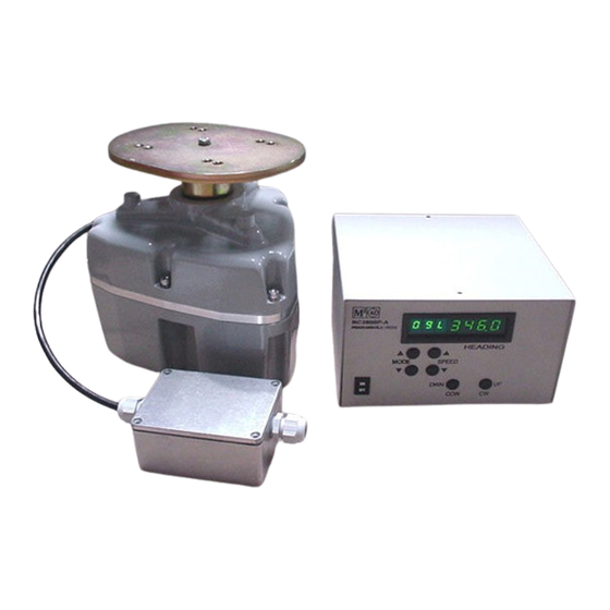
GETTING STARTED (with an OR2800 azimuth rotator) We highly recommend that upon receiving the rotator and controller, you hook it up in the shack and get used to the operation. Here is what you do. 1. Connect the black lead in the rotator pigtail to terminal #1 on the back of the control box. 2. -
Page 5: Front Panel Controls
. 4-23-03 FRONT PANEL CONTROLS “PWR” ROCKER SWITCH Located in the lower left hand corner of the front panel, this button controls AC power to the unit. DIGITAL DISPLAY The digital display panel shows (from left right): MODE, SPEED, HEADING / PROGRAMMING data. Display Digit: #1: (full left): shows the selected MODE for operation or programming. -
Page 6: Run Modes
RUN MODE DESCRIPTIONS AND EXPLANATIONS RUN MODES: Modes 0, 1, AND 2 are RUN modes that activate the positioner with manual or pre- set commands. Momentarily push either MODE button to cycle through Modes 0, 1, and 2. MODE 0: Manual operation mode. Pushing the CCW or DOWN button activates the rotator in the COUNTER-CLOCKWISE direction and the HEADING count will go down. -
Page 7: Programming Modes & Calibration
PROGRAM MODE DEFINITIONS AND EXPLANATIONS PROGRAM MODES: Modes P1-P6 are PROGRAM modes that permit entering, changing, or re- viewing programmed system parameters. PROGRAM modes P20 through P29 are reserved for 10 preset headings. TO CYCLE THROUGH THE VARIOUS PROGRAMMABLE MODES, depress and hold the UPPER mode button in for 3-5 seconds. - Page 8 out becomes. See the “Getting started” section for setup of other types of motor / gear systems like prop pitch rotators or MT’000 series elevation mechanisms. P3 = ‘0’ This is ‘NORTH STOP‘. North is 0.0 or 360 degrees. To set up for south or 180 degree stop, push CW / UP button till display reads ‘180’.
-
Page 9: Programming Presets
PRESET MODE DESCRIPTION AND EXPLANATION MODE P20-P29 = Reserved for entering 10 programmable ‘PRESET’ headings. TO PROGRAM YOUR FAVORITE HEADINGS NOW, CONTINUE WITH THIS STEP OR DO IT LATER. TO PUT YOUR FAVORITE HEADINGS IN NOW , DO THE FOLLOWING: PUSH AND HOLD THE UPPER MODE BUTTON. -
Page 10: Rear Panel And Installation Hints
REAR PANEL TERMINAL STRIP This 6 terminal strip at left serves as cable interface to the rotator unit. The cable supplies power to and data from the rotator. Your multi-conductor cable from the rotator connects here. A ground stud is provided at right end of terminal for shielded cables. -
Page 11: Operation By Computer
OPERATION BY COMPUTER 1. Connect appropriate cable from your computer to Control Unit's DB9 connector on rear panel. 2. Most computers have a ‘HYPER TERMINAL’ or equivalent capability. T o get into Hyper terminal click on your computers ‘Start’ box and go to ‘Programs’. Then slide to ‘Accessories’ and then to ‘Communications’... -
Page 12: Az And El Operation By Computer
USING RC-2800PX’s FOR DUAL CONTROL OF AZIMUTH AND ELEVATION POSITIONERS 3. The RC-2800PX Azimuth Controller circuit board has an additional port to interface with another RC-2800PX for dual control of and MT series Elevation Positioner (Rotator). This is necessary if you plan to control your antenna array in both the azimuth and elevation axes via a computer. -
Page 13: Writing Control Software
USE THE FOLLOWING INFORMATION TO WRITE YOUR OWN CONTROL SOFTWARE SUMMARY OF CONTROLLER COMMANDS Typed commands in lower or upper case, cr = ENTER or carriage return, # = real number including tenths. FUNCTION COMMAND DESCRIPTION SELECT: A or E cr where A = Azimuth, E = Elevation SPEED: where S = 1 (minimum speed) through 9 (maximum) - Page 14 TO SELECT A POSTION (assumes A or E has been entered) Type the command and follow with an ENTER (cr). Positions below 0 or above 360 degrees will cause the display to flash: -select recognized Azimuth and Elevation positions from within your programmed parameters. Positioner will return a confirmation with "P=XXX"...
- Page 15 RC-2800PX / OR2800 TROUBLE SHOOTING SYMPTOM: When rotator is wired to RG-2800PX, the rotator runs just for a second and then stops. And ‘E’ will appear in the mode column of the display. To reset, hit either mode key. Why does this happen? Most commonly, The microprocessor will not let the motor run more than a second if the micro’...
-
Page 16: Trouble Shooting
#1 to #2. 35 to 45 vdc will be present if the box is faulty. Call M2 for an RA (Return Authorization) number so we can be ready for your unit when it arrives. Send it to: M2 Antenna Systems Inc. 4402 N. Selland Av Fresno, CA 93722 We NOW INCLUDE a copy of the power supply and conditioning and the motor control schematic if you prefer to do the repair . -
Page 17: Simplified Theory Of Operation
SIMPLIFIED THEORY OF OPERATION The positioner will not run if it receives no pulses back from the reed switch. The system works like this: terminal #5 on the back panel is supplied voltage from the inter- nal 12 VDC supply. This 12 volts passes through a 2.2k Ohm resistor and then through and opto-isolator and out to terminal #5. -
Page 18: Wiring And Partial Pcb Schematic
FILE NAME / REV. 2N2222 THIS DOCUMENT CONTAINS INFORMATION PROPRIETARY TO 2N3904 NEWSKEM2 M2 ANTENNA SYSTEMS, INC. ANY REPRODUCTION DISCLOSURE OR M2 P/N 1N4004 USE OF THIS DOCUMENT IS EXPRESSLY PROHIBITED EXCEPT AS M2 ANTENNA SYSTEMS, INC. MAY OTHERWISE AGREE IN WRITING. -
Page 19: Warranty
and / or This warranty gives you specific legal rights. You may also have other rights which will vary from state to state or province to province. M2 warrants the OR2800PX Positioner and RC2800PX Control unit against defects in material and workmanship for a period of 12 months from date of purchase. During the war- ranty period, M2 will, at its option, either repair or replace products or components which prove to be defective.
Need help?
Do you have a question about the RC2800PX-AZ and is the answer not in the manual?
Questions and answers