Table of Contents
Advertisement
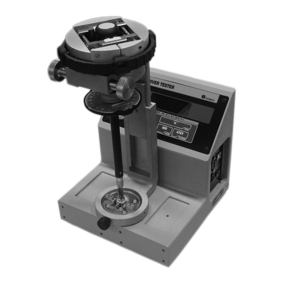
DIGITAL TORQUE SCREWDRIVER TESTER
MODEL TDT3-G
OPERATING INSTRUCTION
TDT3-G
TDT3-G Model
To use this product properly and safely, please read this manual carefully before use. If you have
any question about the product and its operations, please contact your nearest distributor or
TOHNICHI MFG. CO., LTD.
Advertisement
Table of Contents

Related Manuals for Tohnichi TDT3-G


Summary of Contents for Tohnichi TDT3-G
- Page 1 OPERATING INSTRUCTION TDT3-G TDT3-G Model To use this product properly and safely, please read this manual carefully before use. If you have any question about the product and its operations, please contact your nearest distributor or TOHNICHI MFG. CO., LTD.
-
Page 2: Safety Precautions
If you have any question, please contact your nearest You may be exposed to the danger of electric shock. distributor or TOHNICHI MFG. CO., LTD. This operating (5) Do not use this tester with a power voltage other instruction should be stored in a safe place. - Page 3 (4) Before moving this tester to another place, be sure to For replacement or repair of damaged parts, contact turn off the power, remove the power plug from your nearest distributor or TOHNICHI MFG. CO., outlet and disconnect all connecting cables. When LTD.
-
Page 4: Table Of Contents
Contents Safety Precautions ............... 1 1. Features................4 2. Components..............5 3. Specifications..............6 4. Names of Parts............... 8 4-1. Indicator and Operating Parts ......... 8 4-2. Power Source and Output ........9 5. Functions and Operation ..........10 5-1. Run Mode...............10 5-2. -
Page 5: Features
• Judgment function allows users to register upper/lower limit torque value, and have TDT3-G give judgment on the measured value against the registered torque range. Blue light is lit when OK, and red light is lit when the value is out of the registered range. -
Page 6: Components
· Power connector conversion adapter (C type) · Operating instruction · Operation sticker * When purchasing, TDT3-G package includes STA loading device, fixing knob, standard clamp block, and standard bit. When measuring direct reading torque screwdrivers, use LTA loading device (optional). -
Page 7: Specifications
Specifications Model TDT60CN3-G TDT600CN3-G Min. to Max. 2 to 60 20 to 600 Newton 1 digit [cN·m] 0.005 (0.01) 0.05 (0.1) (in M99 mode) Min. to Max. 0.2 to 6 2 to 60 Metric 1 digit [kgf·cm] 0.0005 (0.001) 0.005 (0.01) Torque (in M99 mode) Range... - Page 8 Applicable Model Standard bit LTD/RTD60CN-500CN, NTD/RNTD120CN-260CN, RTDLS260CN-500CN, RTDZ500CN LTD/RTD15CN-30CN, NTD/RNTD15CN-30CN, RTDLS120CN, RNTDLS120CN-500CN, Bit S RNTDZ260CN-500CN, RTDZ260CN, AMLD/AMRD1CN-8CN MEMORY/RESET SWITCH Standard bit Bit S (Scale 1:2) Applicable grip dia. ø7 to ø50 Clamp tool to put Standard bit, input drive 6.35 HEX male ø132 Bit S input drive 6.35 HEX x male (0.7 groove) Maintained position...
-
Page 9: Names Of Parts
Names of Parts 4-1. Indicator and Operating Parts (3) Set A-J display (Lower limit value) (2) Counter display (Upper limit value) (4) ▼ mark display (1) Torque display (8) Statistical procssing key (9) Mode key (6) Count backward key (7) Clear key (5) Count forward key (10) MEMORY/RESET switch (1) Torque display... -
Page 10: Power Source And Output
(8) Statistical processing key (STAT key) Use this key to select samples, maximum value, minimum value or average value. (9) Mode Key (MD key) Push this key to select RUN mode or PEAK mode. Keep pushing this key for 2 seconds or more, then it turns to uper/lower limit value selection. (10) MEMORY/RESET switch After giving judgement to the measured data, it moves the counter forward by one. -
Page 11: Functions And Operation
Torque value increases as torque is applied, and decreases and returns to 0 as it is released. t mark appears above RUN. This mode is used when measuring a direct-reading torque screwdriver or calibrating TDT3-G itself. Push MD key to switch to PEAK MODE. 5-2. PEAK HOLD MODE Torque value increases as torque is applied, and the displayed value stays at the peak value after releasing load. -
Page 12: Deletion Of Data
5-6. Deletion of Data (1) Delete one data Select the data you want to delete by using st key. Push C key to delete the data. (2) Delete a range of data Select the last counter of the data range you want to delete by using st key. Push STAT key, the “Stt”... -
Page 13: Over-Torque Alarm
If applied torque exceeds 110% of the maximum limit of the measurable torque range, the value on the display flashes for alarming. 5-10. Error Display TDT3-G includes self-check function, and Err1-9 will be displayed when there is an error. <<when Err1-5 appears>> • Turn off the power, and turn it on without touching any keys. -
Page 14: Various Settings
Various Settings Refer to below table for various settings, functions and operation. 6-1. Settings • Registration of Upper/Lower limit value Upper Lower Main Display Setting Subject Left Left Default Select TDT60CN3 (TDT600CN3) Screen Screen Select subject to set torq-S PArA-S 4 different measurement unit by t mark Measuring unit Unit... - Page 15 6-2. Registration of Upper/Lower Limit Value • Changing to setting mode At no load condition, push C => STAT => MD key in order, then the screen shows item selection after “----”. • Selecting items to set Register upper/lower limit value and other parameter settings. While it shows “torq-S”, press MD key or STAT key then it proceeds to next.
- Page 16 • Register lower limit value (A) (default: 0) Register lower limit value (A) for judgment. Use s key to select digit, t key to select number, and STAT key to decide and proceed to upper limit (B) setting. (If you push MD key, it proceeds to next without saving. If you push C key, it returns to measuring display.
- Page 17 • Key operation sound (default: on) Turn on or off the operation sound. Even if you set “oFF”, over-torque alarm cannot be cancelled. Using st key, select “on” or “oFF” and push STAT key to decide. It proceeds to communication setting. (If you press C key, it returns to measuring display without setting.) •...
- Page 18 (4) Parity (default: none) Set parity Using st key, select “nonE” for none, “EVEn” for even, “odd” for odd and push STAT key to decide. It returns to measuring condition. (If you press C key, it returns to measuring display without setting.) •...
-
Page 19: Measuring A Torque Screwdriver (Recommended)
Measuring a Torque Screwdriver (Recommended) 7-1-1. Operating Temperature Measuring should be conducted at temperature in 18-28°C range. Temperature fluctuation should be within ±1°C. 7-1-2. Check the Following before Calibrating the Torque Screwdriver. (1) Torque screwdriver tester should be set at stable working table. (2) For calibration of direct reading torque screwdriver, make sure to read the value from upright position to avoid reading errors by angle. - Page 20 7-3. How to Measure (1) Set TDT3-G on stable work table free of vibration. (2) Connect AC adapter to the power jack on side of TDT3-G. Make sure the power is switched off, then connect the adapter to power source.
- Page 21 (8) Check the measured value of the torque screwdriver. (9) Put the torque screwdriver through the loading device and fix it by the clamp tool. If the resin grip is on the screwdriver, remove it before setting. 2. Use clamp tool to rotate the 1.
-
Page 22: External Output
External Output 8-1. Printer Output Connect TDT3-G and the printer (EPP16M2) using the cable (No. 382). Set the communication output format to “Prn” and other communication settings compliant with printer settings (Refer to chapter 6 for details.) * Do not use the cable for printer and the USB cable at the same time. - Page 23 • Continuous printing In case of memory mode 1000 1:OK SET A ← Memory counter: judgement result, upper/lower 30.000cN・m ← Limit value symbol, torque unit 21:HI SET A 31.000cN・m 3: ← “--“ for no judgement”--” ==.===cN・m ← Torque value ===== ・ ・ ・...
-
Page 24: Pc Output
8-2. PC Output Connect TDT3-G and external device by cable (No. 383 or No. 385). Set the communication output format to “PC” and set it in line with other communication settings. (Refer to Chapter 6 for details.) * Do not use RS232C cable and USB cable at the same time. -
Page 25: Optional Accessories
If it still shows the error, contact your nearest distributor or TOHNICHI. Err8 CPU/memory problem Contact your nearest distributor or TOHNICHI for repair. Err9 Torque sensor/internal Push C key at no load condition. If the error is cancelled, it can be used. -
Page 26: Calibration Procedure
(2) Calibration procedure 1) Place TDT3-G on the measurement table in a horizontal position. 2) Turn on the power of TDT3-G. (After the power is turned on, leave the unit as it is for 30 minutes or more for stabilization.) 3) Set TDT3-G in RUN mode. - Page 27 Weights Information for TDT3-G Calibration Newton Unit TDT60CN3-G TDT600CN3-G Measuring Loading Measuring Loading Point Weights Remarks Point Weights Remarks [cN·m] [kg] [cN·m] [kg] 0.1020 Scale Pan + 2g 0.2039 Scale Pan + 203.9g 1.020 Scale Holder + 20g 2.039 Scale Holder + 1.039kg 1.530...
- Page 28 Scale Holder + 3.320kg 2.880 Scale Holder + 1.880kg 5.760 Scale Holder + 4.760kg Required weights Components of TDT3-G Calibration Kit: (1) For TDT60CN3-G: 1 piece of WS-TCL2 Calibration Scale Pan 100g 1 pc. required. Calibration Scale Holder 1 kg 1 pc.
Need help?
Do you have a question about the TDT3-G and is the answer not in the manual?
Questions and answers