VIA Technologies Mobile360 Installation Manual
Forklift safety system
Hide thumbs
Also See for Mobile360:
- Quick start manual (20 pages) ,
- Calibration manual (72 pages) ,
- Quick start manual (18 pages)

Related Manuals for VIA Technologies Mobile360


Summary of Contents for VIA Technologies Mobile360
- Page 1 INSTALLATION GUIDE VIA Mobile360 Forklift Safety System Left, Right & Rear People Detection 1.00-20072022...
- Page 2 OTHERWISE MADE AVAILABLE TO YOU THROUGH VIA, INCLUDING, BUT NOT LIMITED TO DIRECT, INDIRECT, INCIDENTAL, PUNITIVE, AND CONSEQUENTIAL DAMAGES, UNLESS OTHERWISE SPECIFIED IN WRITING. VIA Technologies, Inc. reserves the right the make changes to the products described in this manual at any time without prior notice. Regulatory Compliance FCC-A Radio Frequency Interference Statement This equipment has been tested and found to comply with the limits for a class A digital device, pursuant to part 15 of the FCC rules.
- Page 3 Drivers should always abide by safe driving regulations when using the VIA Mobile360 7" display (upgrade option), and should always pay attention to the operating environment, even when viewing the display.
- Page 4 VIA Mobile360 Forklift Safety System 3PD Installation Guide • It may not be possible to install this product on every type or model of forklift. Before purchasing this product, please confirm with the VIA whether this product is suitable for the type or model of the forklift you intend to install it on.
- Page 5 VIA Mobile360 Forklift Safety System 3PD Installation Guide Warranty Process During the warranty period, if this product breaks down and needs to be repaired, please follow the process below: 1. If you purchased this product from a distributor, please contact them.
- Page 6 VIA Mobile360 Forklift Safety System 3PD Installation Guide Revision History Version Date Remarks 1.00 20/07/2022 Initial Release...
- Page 7 VIA Mobile360 Forklift Safety System 3PD Installation Guide Packing List • 1 x VIA Mobile360 M500 system • 2 x Vibration dampening strips • 3 x IP67 FOV-190° left/right/rear cameras with mounting brackets (3M cable) • 3 x Strong magnets with 6 x M5*12mm bolts •...
-
Page 8: Table Of Contents
VIA Mobile360 Forklift Safety System 3PD Installation Guide Table of Contents Product Overview ............................1 System Layout ............................1 System Dimensions ..........................2 Installation ..............................3 System Preparation ..........................3 2.1.1 Inserting a MicroSD Card ....................... 3 2.1.2 Securing the Waterproof Cover ..................... 4 2.1.3... - Page 9 VIA Mobile360 Forklift Safety System 3PD Installation Guide DC Power Module ..........................44 A.3.1 Package Contents ......................... 44 A.3.2 Installation ........................... 44 Appendix B Troubleshooting ..........................48...
- Page 10 Figure 40: Assembling the speed sensor and mounting bracket ................ 38 Figure 41: Speed sensor installation ........................39 Figure 42: Connecting speed sensor to the VIA Mobile360 M500 system ............40 Figure 43: 7" CVBS display interface with rear camera view only and speed reading........41 Figure 44: 7"...
- Page 11 VIA Mobile360 Forklift Safety System 3PD Installation Guide List of Tables Table 01: MicroSD card recording times ......................3 Table 02: Maximum side-to-rear camera distances .................... 8 Table 03: System LED status ..........................18 Table 04: People detection audio alerts ......................20 Table 05: 7"...
-
Page 12: Product Overview
Simple to install and maintain, the VIA Mobile360 Forklift Safety System comes with 3 people detection cameras, a high-quality speaker and optional accessories such as a 7” CVBS display and a forklift speed sensor kit to provide a complete out-of-the-box solution for a wide range of forklifts. -
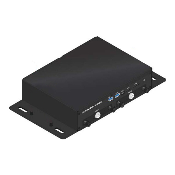
Page 13: System Dimensions
VIA Mobile360 Forklift Safety System 3PD Installation Guide 1.2 System Dimensions 56.8mm 178mm Figure 03: Front view system dimensions 194.6mm 167mm Figure 04: Side view system dimensions... -
Page 14: Installation
I/O covers for unused ports as well as to secure the vibration dampening strips to the bottom of the system. 2.1.1 Inserting a MicroSD Card The VIA Mobile360 M500 system requires a MicroSD card to be installed in order to record video in real time. A 32GB MicroSD card is provided in the system package. Note: Failure to install a MicroSD card will not affect the operation of the system, but video will not be saved. -
Page 15: Securing The Waterproof Cover
To cover the unused ports, follow the instructions below: 1. On the front I/O panel of the VIA Mobile360 M500 system, the DIO 1, DIO 2 and the CAN/COM ports are not required for the standard setup. -
Page 16: Attaching The Vibration Dampening Strips
VIA Mobile360 Forklift Safety System 3PD Installation Guide 2. On the rear I/O panel of the VIA Mobile360 M500 system, the CVBS port (display) and the ANT-M and ANT-D (for 4G) antenna ports are not required for the standard setup. -
Page 17: Via Mobile360 M500 System Installation
VIA Mobile360 Forklift Safety System 3PD Installation Guide 2.2 VIA Mobile360 M500 System Installation Before Installing the VIA Mobile360 M500 system on a forklift, a suitable location should be determined based on the following criteria: • A flat surface with enough spacing to accommodate the system chassis and room for attaching the cables. -
Page 18: Camera Installation
3m cables to be installed on the target forklift. Each camera comes in a labeled box within the VIA Mobile360 Forklift Safety System package and include color- coded cables (brown for left, black for right and purple for rear) for easy identification. Also included for each camera are a strong magnet with two M5*12mm bolts, one piece of double-sided 3M tape and two M5*25mm Molly bolts. -
Page 19: Scenario A: Side Cameras < 2.3M From Rear Camera
VIA Mobile360 Forklift Safety System 3PD Installation Guide 2.3.1 Scenario A: Side Cameras < 2.3m from Rear Camera If the side cameras can be installed no further than 2.3m (X) from the left/right of the rear camera, the following table can be used to determine the maximum "Y' value the cameras can be installed from the rear camera towards the front of the vehicle. -
Page 20: Attaching The Cameras
VIA Mobile360 Forklift Safety System 3PD Installation Guide Figure 14: Scenario B camera installation 2.3.3 Attaching the Cameras After determining the ideal installation locations for each camera, follow the detailed instructions below to install the cameras: 1. Camera and mount assembly: There are two methods to fix the camera to the forklift: −... -
Page 21: Figure 16: Marking Installation Location And Drilling
VIA Mobile360 Forklift Safety System 3PD Installation Guide 2. For each camera, mark the installation location with a line parallel to the ground/vehicle edge. If drilling will be used, also mark the location of the screw holes on the bottom of the camera bracket and drill the holes. -
Page 22: Speaker Installation
Figure 18: Installing cameras with Molly bolts 2.4 Speaker Installation The VIA Mobile360 Forklift Safety System comes with a 2W speaker which is required to playback the audio alerts for the driver. To install the speaker, follow the steps below: 1. -
Page 23: Wi-Fi/Gps Antenna Installation
VIA Mobile360 Forklift Safety System 3PD Installation Guide 2.5 Wi-Fi/GPS Antenna Installation The VIA Mobile360 Forklift Safety System comes with a Wi-Fi and GPS antenna pack which is required for ensuring the Wi-Fi network signal strength in order to connect the VIA Mobile360 WorkX app to. -
Page 24: Peripheral Cabling And Connection
Each cable is color-coded to match the corresponding port on the VIA Mobile360 M500 system. Connect the cables to the correct port on the VIA Mobile360 M500 systems according to the color labels as follows: Front Panel I/O •... -
Page 25: Connecting Ground, Acc And Power
Connect the GPS antenna (green cable) to the "GPS" port designated in green. Figure 23: Rear I/O cable connections 2.6.1 Connecting Ground, ACC and Power The power cable for the VIA Mobile360 M500 system includes three cables to be connected to the fuse box of the target forklift as follows: •... -
Page 26: Figure 25: Blade Fuse Holder Cables
2. Loosen the screw and place the Y connector on the end of the black wire on the VIA Mobile360 M500 system power cable beneath the screw. Tighten the screw so the wire is firmly held. - Page 27 VIA Mobile360 Forklift Safety System 3PD Installation Guide 3. Refer to the vehicle's user manual to find the location of the fuse box. Then check the ACC fuse and power specification and location on the fuse box cover. 4. Pull out the ACC fuse from the vehicle's fuse box.
- Page 28 11. Plug in the blade fuse holder cable into the positive power fuse slot in the fuse box. 12. Route the cable back to the VIA Mobile360 M500 system and connect the cable to the "PWR" port on the rear I/O panel designated in red.
-
Page 29: Turning System On/Off
When the system has completely shut down, the system power LED indicator will turn off. The entire shutdown process takes about 30 seconds. 2.7.1 System Reset The VIA Mobile360 M500 system includes a reset button which can be used to either perform a system power reset or a complete factory reset. •... -
Page 30: Safety Alerts & Camera Calibration
3. Safety Alerts & Camera Calibration To provide drivers with the smart situational awareness needed to safely maneuver around crowded and noisy working spaces, the VIA Mobile360 Forklift Safety System supports people detection through its left, right and rear cameras. -
Page 31: Camera Calibration
3.1.1 Camera Calibration Before the VIA Mobile360 Forklift Safety System can provide people detection alerts, each camera needs to be calibrated using the VIA Mobile360 WorkX app. Follow the steps below to download the app and to connect to a target device: 1. -
Page 32: Figure 28: Camera Calibration Pattern Placement
1. Before using the VIA Mobile360 WorkX app to calibrate the cameras, place the calibration pattern (which is printed on the bottom side of the VIA Mobile360 Forklift Safety System box on the ground directly in front of the camera at a distance of 2 meters, as shown below in Figure 27. -
Page 33: Figure 29: Left/Rear/Right Camera Angle Adjustment
2m, tap on 'Next' to continue. 5. Adjust the camera to align the target overlay in the VIA Mobile360 WorkX app with the edge of the black pattern printed on the box and tap on 'Next'. - Page 34 VIA Mobile360 Forklift Safety System 3PD Installation Guide 6. The next step is to set the detection area that people detection alerts will be triggered within. In the interface there are two icons on the left-hand side to set the critical/warning zone boundary line distance and the max distance for warning detections (optional).
- Page 35 VIA Mobile360 Forklift Safety System 3PD Installation Guide 9. After all criteria for detection area are set, press the "Confirm" button in the top right-hand corner of the app to complete the calibration process and return to the "Camera Calibration" tab in the app.
-
Page 36: Via Mobile360 Workx App
4. VIA Mobile360 WorkX App VIA Mobile360 WorkX app supports Android v5.0 and higher and iOS v12 and higher. The app can be used to calibrate the three cameras, adjust settings and upgrade the firmware for the VIA Mobile360 Forklift Safety System, as well as view and download videos stored on the system's MicroSD Card. -
Page 37: Upgrading System Firmware
4.2 Upgrading System Firmware When a new firmware version is available for the VIA Mobile360 Forklift Safety System, a notification will appear when first opening the VIA Mobile360 WorkX app. Press "OK" to download the new firmware to the mobile device. -
Page 38: App Menu
VIA Mobile360 Forklift Safety System 3PD Installation Guide 4.3 App Menu The menu for the VIA Mobile360 WorkX app is located along the bottom of the app interface and includes the four items described below: • Cameras - The cameras tab provides the calibration methods for each camera as well as live streams of each camera after calibration has been completed. -
Page 39: Settings
2. Enter the new Wi-Fi name and password. 3. Tap on "OK" to save the changes. Note: After changing the SSID and/or Password, the VIA Mobile360 WorkX App will need to reconnect to the system as described in section 4.1 using the new name and/or password. -
Page 40: Album
From the “Album” tab, users can playback or download videos and alert images stored on the MicroSD card installed in the VIA Mobile360 Forklift Safety System. Up to 500 alert images can be stored, while the number of videos that can be stored depends on the MicroSD card's storage capacity. - Page 41 Local: Alert images and videos downloaded to the connected mobile device are displayed in the “Local” tab. Individual folders with subfolders for alert images and videos will be created for each VIA Mobile360 Forklift Safety System that has downloaded items stored on the connected mobile device. These alert images and videos are accessible at any time.
- Page 42 VIA Mobile360 Forklift Safety System 3PD Installation Guide • If copy is selected, a notification will appear confirming the files have been copied. Press "OK" to continue. • If share is selected, the phone will provide options to share the files to email, social media etc. Select the desired methods to share and complete the corresponding process.
-
Page 43: Appendix A Optional Accessories
Ensure that the forklift is turned off before installing or uninstalling an optional accessory. A.1 7" CVBS Display Kit An optional 7" CVBS display kit is available for the VIA Mobile360 Forklift Safety System for increased driver awareness of the vehicle's surrounding environment. Live video streams from the rear and side cameras (left and right) can be viewed on the 7”... -
Page 44: Installation
VIA Mobile360 Forklift Safety System 3PD Installation Guide A.1.2 Installation Follow the steps below to install the CVBS display panel: Display and mount assembly: There are two methods to fix the display to the forklift: Magnet and 3M Tape: 1. Before installing on the forklift, assemble the CVBS display mount by attaching the included magnets to the bottom of the mounting bracket with the four M5*12mm bolts. -
Page 45: Figure 33: 7" Cvbs Display Mount Installation With Drilling
Figure 34: 7" CVBS display installation 6. Route the cable back to the VIA Mobile360 M500 system, ensuring no part of the cable is hanging or exposed from the forklift to prevent accidental disconnection or injury. It is suggested to use zip ties or... -
Page 46: Figure 35: 7" Cvbs Display Cable Connections
It is strongly recommended to secure the CVBS cable connection with LOCTITE 243 Threadlocker (not included) prior to installation. See section 2.6 for instructions. Figure 35: 7" CVBS display cable connections 8. Start the forklift and the display will automatically be detected by the VIA Mobile360 Forklift Safety System and powered on. -
Page 47: Display Interface
A.1.3 Display Interface Once connected, the 7" CVBS display provides the driver with rear camera-only or all-camera live views (based on user-configured settings in the VIA Mobile360 WorkX app), as well as visual alerts for people detection warnings. The following images represent the 7" CVBS display interface depending on the... -
Page 48: Display Buttons
Person in warning zone detected Person in critical zone detected Table 06: 7" CVBS panel alert icons The default UI language is English but can be changed to other supported languages with the VIA Mobile360 WorkX app. See section 4.3.2 for more details. -
Page 49: Speed Sensor Kit
VIA Mobile360 Forklift Safety System 3PD Installation Guide A.2 Speed Sensor Kit The optional speed sensor accessory kit is available for use with the VIA Mobile360 Forklift Safety System to determine a target forklift's speed and set alerts for speeding. -
Page 50: Connecting To System
Follow the steps below to attach the speed sensor to the VIA Mobile360 M500 system. 1. Route the speed sensor cable back to the VIA Mobile360 M500 system, ensuring no part of the cable is hanging or exposed from the forklift to prevent accidental disconnection or injury. It is suggested to use zip ties or tape to help secure the cable when routing. -
Page 51: Configuration
4.1. 3. Tap on the 'Settings' tab in the VIA Mobile360 WorkX app to find the speed sensor's activation and configuration options in the 'Optional Accessories' section. 4. Drive forward for a short distance ensuring the magnet has passed the speed sensor at least once. -
Page 52: Display Interface And Alerts
A.2.5 Display Interface and Alerts When the speed sensor is installed, the VIA Mobile360 Forklift Safety System will be able to detect the forklift's movement, display speed on the 7" CVBS display interface and trigger over-speeding audio alerts. -
Page 53: Deactivation
Forklift Safety System as described in section 4.1. 3. Tap on the 'Settings' tab in the VIA Mobile360 WorkX app to find speed sensor settings in the 'Optional Accessories' section. 4. Make sure that the speed sensor has been activated. - Page 54 4. Deactivate the speed sensor by tapping on the activation toggle on the right-hand side. 5. After deactivation, the speed sensor can be removed from the forklift. Note: If the speed is disconnected before deactivation, the VIA Mobile360 Forklift Safety System will continue to display speed icon on the CVBS display.
-
Page 55: Figure 45: Dc Power Module
2 x Vibration dampening strips Figure 45: DC Power Module A.3.2 Installation The DC power module for the VIA Mobile360 Forklift Safety System includes three cables to be connected to the designated EV forklift: • Yellow wire - ACC/IGN, enables system to be turned on and off with the vehicle •... - Page 56 VIA Mobile360 Forklift Safety System 3PD Installation Guide Make sure the vehicle is turned off and follow the steps below to install the DC power module: 1. Attach the two vibration dampening strips to the bottom of the DC power module by removing the adhesive backings and aligning with the screw holes along each side.
- Page 57 (maximum distance of 2.3M from the DC power module) can reach the red power (PWR) port of the VIA Mobile360 M500 system. Once the location is determined, mark the screw holes on either side of the module and drill holes.
- Page 58 Ensure all cables are tucked away and fasten securely within the forklift to ensure they will not be damaged during operation. 10. Finally, turn on the forklift and check if the VIA Mobile360 Forklift Safety System powers on. Turn the forklift off to ensure the VIA Mobile360 Forklift Safety System also turns off.
- Page 59 VIA Mobile360 Forklift Safety System 3PD Installation Guide Appendix B Troubleshooting Check the table below to troubleshoot if the system is not working properly. If the symptom is not listed below or the proposed solution does not bring your system back to an operational state, check the warranty section for further assistance.
- Page 60 VIA Mobile360 Forklift Safety System 3PD Installation Guide People Detection Issues Refer to Symptom Possible Cause Solution Section Check VIA Mobile360 WorkX app Critical/Warning Alerts and select "All Alerts" or "Critical 4.3.2 were not enabled Alerts Only" for rear and side cameras (left and right).
- Page 61 VIA Mobile360 Forklift Safety System 3PD Installation Guide Speaker Issues Refer to Symptom Possible Cause Solution Section Speaker detached from Check the speaker connection the system. No sound coming from the speaker System volume was too Raise the system volume 4.3.2...
- Page 62 Taiwan Headquarters Japan China 1F, 531 Zhong-zheng Road, 940 Mission Court 3-15-7 Ebisu MT Bldg. 6F, Tsinghua Science Park Bldg. 7 Xindian Dist., New Taipei City 231 Fremont, CA 94539, Higashi, Shibuya-ku No. 1 Zongguancun East Road, Taiwan Tokyo 150-0011 Haidian Dist., Beijing, 100084 Japan China...
Need help?
Do you have a question about the Mobile360 and is the answer not in the manual?
Questions and answers