Table of Contents

Subscribe to Our Youtube Channel
Related Manuals for NARGESA CC90


Summary of Contents for NARGESA CC90
- Page 1 2-AXIS POSITIONER LIMIT NON-MANDREL PIPE BENDER CC90 INSTRUCTIONS BOOK PRADA NARGESA, S.L Ctra. de Garrigàs a Sant Miquel s/n · 17476 Palau de Santa Eulàlia (Girona) SPAIN Tel. +34 972568085 · nargesa@nargesa.com · www.nargesa.com...
- Page 3 Thank you for choosing our machines www.nargesa.com...
-
Page 5: Table Of Contents
CONTENTS 1. ACCESSORY DETAILS ......................3 1.1. Accessory Identification ....................3 1.2. Dimensions ........................3 1.3. Accessory Description ....................4 1.4. General Characteristics ....................4 1.5. Machine Parts ....................... 5 2. TRANSPORT AND STORAGE ....................6 2.1. Transport ........................6 2.2. -
Page 6: Accessory Details
1. ACCESSORY DETAILS 1.1. Accessory Identification Make NARGESA Type of accessory 2-axis positioner limit Model CC90 1.2. Dimensions Figure 1. Outside dimensions of Pipe Bender Limit CC90 - 6 -... -
Page 7: Accessory Description
• Automatic anti-collision control • Easy handling and preparation for complex parts PRADA NARGESA S.L is not liable for any damages that may be caused due to improper use or a breach of the safety rules by users. 1.4. General Characteristics... -
Page 8: Machine Parts
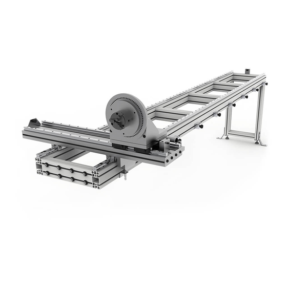
1.5. Machine Parts Vertical support Longitudinal cart Adjustable stopper Floor securing part Cross cart Clamps Pipe securing tray Cross limit (Longitudinal Adjustment guide limit switch sensor (inductive) - 8 -... -
Page 9: Transport And Storage
2-AXIS POSITIONER LIMIT CC90 2. TRANSPORT AND STORAGE 2.1. Transport The limit should be moved as follows: - Along the bottom through the pallet at the base of the box using a forklift or lift truck as indicated in the illustration. -
Page 10: Maintenance
Keeping the moving parts on the limit clean is recommended to ensure proper operation and extend the service life. To grease the limit skids on the CC90, simply grease all the limit greasers: 8 in all, every 30 days . Front view Rear view ATTENTION: To grease the Limit, you must stop the machine and press the “Emergency Stop”... -
Page 11: Limit Location And Installation
2-AXIS POSITIONER LIMIT CC90 4. LIMIT LOCATION AND INSTALLATION 4.1. Limit Location Try to position the machine and limit in the proper location so they do not have to be moved; otherwise, follow the steps described in the Transport section (no. 2). Position over a smooth, level surface to prevent vibrations and movements during bending operations . -
Page 12: Installing The Limit
4.4. Installing the Limit 1. Install the vertical limit support by inserting it into the guides on the end and screw in. 2. Screw in the vertical support using the four screws. 3. Install the guide covers by firmly pressing. Use a plastic hammer if necessary. - 12 -... - Page 13 2-AXIS POSITIONER LIMIT CC90 ATTENTION: To secure the limit to the machine, you must stop the machine and press the “Emergency Stop” button. 4. Unscrew and remove the side shelf of the machine. 5. We lead the end of the inductive wire from the inside to the outside of the machine, through the hole in the shelf.
- Page 14 6. Install the limit on the side of the machine indicated in the image. Remove the 8 screws supplied with the machine and screw the limit to it using the 8 screws supplied with the limit. 7. We put the shelf back in its place and attach it to the machine by fastening the bolts. - 14 -...
- Page 15 2-AXIS POSITIONER LIMIT CC90 8. Level the machine on the two axles. 9. Level the limit on the two axles. - 15 -...
- Page 16 10. Adjust the height of the vertical support using the two adjustable legs, adjusting the limit to a level posi- tion. 11. Check that the limit is completely level before definitively securing it to the machine by tightening the 8 screws well.
- Page 17 2-AXIS POSITIONER LIMIT CC90 12. Secure the two securing parts supplied with the limit to the ground. 13. Connect the machine inductive sensor cable by tightening it with the limit inductive sensor. - 17 -...
- Page 18 14. Place the inductive sensor in the limit chassis support and secure it with the bolt. Start the machine using the power switch. 15. Slide the longitudinal cart until the inductive sensor LEDs turn off. This means it was detected. Make sure the clamps do not collide with the machine in this cart position.
- Page 19 2-AXIS POSITIONER LIMIT CC90 16. The following message appears on the control screen. Press so it will disappear. 17. Press to access the menu, then press . Enter the password. 18. Access the E/S menu and activate the backgauge limit switch. Press to return to the home screen.
-
Page 20: Adjusting The Limit
4.5. Adjusting the Limit The bender switch CC90 is adjusted by our technicians before the machine is sent to the customer. How- ever, you need to check and re-adjust the limit before working with it. 1. Insert a pipe measuring 1200 mm minimum in the limit as indicated in section 5.2. Securing the Pipe to the Limit. - Page 21 2-AXIS POSITIONER LIMIT CC90 3. Adjust the longitudinal cart with the stopper and loosen the screws in the adjustment guide. 4. Move the cart slowly until the mark on the pipe is lined up with the mark on the counter-shape and the main roller.
- Page 22 5. As soon as the mark on the pipe is lined up, tighten the screws on the adjustment guide and remove the pipe. - 22 -...
-
Page 23: Instructions For Use
5. INSTRUCTIONS FOR USE 5.1. Limit Features and Use The CC90 limit is used to position the pipe in an exact position for bending. 5.2. Securing the Pipe to the Limit Secure the pipe to the securing tray by adjusting the clamps using the wrench supplied with the limit. Make sure the material is completely secured to the tray and in contact with the base of the tray. -
Page 24: Adjusting The Longitudinal Limits
5.4. Adjusting the Longitudinal Limits The CC90 limit is equipped with 6 adjustable stoppers which can be adjusted. It includes a millimeter and inch ruler which shall be used to adjust the stoppers to the desired measurement. Secure the stoppers... -
Page 25: Adjusting The Cross Limit
2-AXIS POSITIONER LIMIT CC90 5.5. Adjusting the Cross Limit Adjust the cross limit so the pipe is positioned parallel to the limit chassis. Move the cross limit by unscrewing the two screws and moving the limit. Use the ruler to position the limit to the same size as the radius of the main roller. As soon as it is in the correct position, secure it to the longitudinal cart by tightening the two screws. -
Page 26: Adjusting The Pipe Rotation Angle
5.6. Adjusting the Pipe Rotation Angle Adjust the rotation angle to the degrees at which the pipe will rotate. To define these degrees, loosen the corresponding screw a few millimeters without fully unscrewing the screw so the tray to be rotated stops at the chosen degrees. -
Page 27: Technical Annexes
Technical Annex Non-Mandrel Pipe Bender Limit CC90 General blow-up view Limit structure... - Page 28 General blow-up view - 28 -...
- Page 29 2-AXIS POSITIONER LIMIT CC90 - 29 -...
- Page 30 - 30 -...
- Page 31 2-AXIS POSITIONER LIMIT CC90 - 31 -...
- Page 32 - 32 -...
- Page 33 2-AXIS POSITIONER LIMIT CC90 Limit structure - 33 -...
- Page 34 - 34 -...
- Page 36 OUR RANGE OF MACHINERY IRON WORKERS SECTION BENDING NON-MANDREL HORIZONTAL PRESS MACHINES PIPE BENDER BRAKE TWISTING/SCROLL HYDRAULIC PRESS HYDRAULIC SHEAR BENDING MACHINES BRAKES MACHINES IRON EMBOSSING END WROUGHT IRON GAS FORGES MACHINES MACHINES BROACHING POWER HAMMERS PRESSES FOR LOCKS MACHINES...
Need help?
Do you have a question about the CC90 and is the answer not in the manual?
Questions and answers