Table of Contents
Advertisement
Quick Links
Advertisement
Table of Contents

Related Manuals for Alpha MED Scientific MED64


Summary of Contents for Alpha MED Scientific MED64
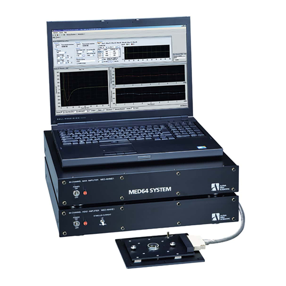
- Page 1 MED64 System (MED64-Basic/Quad II/Allegro) Manual...
-
Page 2: Table Of Contents
2.1.3. Accessories of the MED64 Main Amplifier ……………….. 3 2.1.4. Accessories of the MED64 Head Amplifier ……………….. 3 3. Setup of the MED64 System - procedure common to Basic, Quad II, and Allegro ……………….. 3 3.1. Considerations for the position of devices ……………….. 3 3.2. - Page 3 7.2. Explanation of the technology ……………….. 29 7.2.1. Signal acquisition by the MED64 system ……………….. 29 7.2.2. Electric stimulation by the MED64 system – Applying current to the micro electrode array ……………….. 29 7.2.3. Stimulus artifact and biphasic stimulation ……………….. 30 7.2.4.
-
Page 4: Introduction
◆ The MED64 System is a micro electrode array (MEA) system commercialized for the first time in the world in 1997. Since then, the MEA system has been widely used in the United States and the EU for basic research in the fields of the central nervous system and the cardiovascular system. -
Page 5: Part Names And Functions
❹ ❺ ❼ ➊INPUT ….. An analog input terminal to input signals from the MED64 Head Amplifier. It is connected to the OUTPUT of the MED64 Head Amplifier via the 68-pin SCSI cable. ➋OUTPUT ….. An analog output terminal to connect an external device (MED Feedback Stimulator etc.) ➌DIO 1、2、3 ….. -
Page 6: Accessories Of The Med64 Main Amplifier
A faraday cage or vibration isolation table that is typically necessary for an electrophysiological experiment is not necessary for the MED64 System, but the MED64 System should be set up on a stable table without vibrations, such as a laboratory desk. A desk of about 100 cm width and 75 cm depth is necessary. -
Page 7: Considerations For The Position Of Devices
Above is an image of the ideal positions of the components. The user can perform an experiment easily when there is a sufficient space next to or at the back of the laboratory desk with the power strip on the floor (as shown in Layout Sample 2). If the MED64-Quad II is to be used in combination with four perfusion systems, a larger space will be necessary. -
Page 8: Setup Of The Med64-Basic
❶ ❹ ➊Output terminal ….. To connect to INPUT of the MED64 Head Amplifier via the accessory, the 68-pin SCSI cable. ❷Fixation screw ….. To fix the fitted top unit and the base plate with a MED Probe attached. ❸Contact pin ….. To contact with the MED Probe terminal to read signals. -
Page 9: Positioning Of The Terminal Of The Med Connector
➎Connect the ground wire wound on the 68-pin SCSI cable to the SIGNAL GND terminal of the MED64 Head Amplifier. ➏Connect the USB port (type-B) of the MED64 Head Amplifier and the USB port (type-A) of the data acquisition PC (USB2.0 is preferable), using the USB cable ➐Connect the power adaptor cables to both amplifiers. -
Page 10: Electric Shield With Aluminum Foil
Note: Although the MED Connector is made from aluminum, its surface is coated and insulated from the aluminum foil. Make sure that the aluminum foil is grounded to the SIGNAL GND terminal of the MED64 Head Amplifier when a sheet of aluminum foil is placed under the MED Connector, even if the baseline noise level is within an acceptable range. -
Page 11: Maintenance Of The Med Connector
About the details of noise check, refer to p.19 “Noise check by operating the Mobius - procedure common to Basic, Quad II, and Allegro”. Also, for the details of operating the Mobius refer to “MED64 Mobius Tutorial.” Refer to the relevant application note for the preparation of specimens used for the experiment. -
Page 12: Setup Of The Med64-Quad Ii
➌Ground wire with an bagworm clip ….. To connect to a platinum wire with a perfusion cap when a perfusion system is used. ❹Output terminal ….. To connect to the INPUT terminal of the MED64 Head Amplifier via the 20-pin SCSI cable. -
Page 13: Positioning Of The Terminal Of The Med Duet Connector
➎Connect the ground wire wound on the 20-pin SCSI cable to the SIGNAL GND terminal of the MED64 Head Amplifier. ➏Connect the USB port (type-B) of the MED64 Head Amplifier and the USB port (type-A) of the data acquisition PC (USB2.0 is preferable), using the USB cable ➐Connect the power adaptor cables to both amplifiers. -
Page 14: Preparation For The Noise Check - Attaching The Med Probe16
About the details of noise check, refer to p.19 “Noise check by operating the Mobius - procedure common to Basic, Quad II, and Allegro”. Also, for the details of operating the Mobius refer to “MED64 Mobius Tutorial.” Refer to the relevant application note for the preparation of specimens used for the experiment. -
Page 15: Connections Among Devices
➍Output terminal ….. To connect to the INPUT terminal of the MED64 Head Amplifier via the 20-pin SCSI cable. ❺20-pin SCSI cable (2 m x 4) ….. To connect the output terminal and the INPUT terminal of the MED64 Head Amplifier (the specification is different from the 20-pin SCSI cable for the MED Duet Connector). -
Page 16: Positioning Of The Terminal Of The Med Multi-Well Connector
Note: The ground terminal of the MED Multi-well connector must be grounded to the SIGNAL GND terminal of the MED64 head amplifier. If not grounded, it will be affected by external noise. 3.5.3. Positioning of the terminal of the MED Multi-well Connector The electrode number will be assigned as the below when place the MED Multi-well Connector with its output terminal and the 20-pin SCSI cable on the right side. -
Page 17: Preparation For The Noise Check - Attaching The Med Multi-Well Probe
About the details of noise check, refer to p.19 “Noise check by operating the Mobius - procedure common to Basic, Quad II, and Allegro”. Also, for the details of operating the Mobius refer to “MED64 Mobius Tutorial.” Refer to the relevant application note for the preparation of specimens used for the experiment. - Page 18 Input Range (mV): 5.0、Low cut freq (Hz): 1、High cut freq (Hz): 10000 Note: To call up Noise_check.moflo, the workflow communicates with the MED64 Main Amplifier via the USB cable. If the Amplifier is not turned on, a pop-up window appears with an error message, as shown in the right figure.
-
Page 19: Combining With A Perfusion System
5. Combining with a perfusion system This section explains the procedure for setting up a perfusion system when the MED64 System is used in combination with it. The perfusion system recommended to be used in combination with the MED64 System consists of the following: 1) MED Perfusion Cap Kit 【MED-KCAP01TU】... -
Page 20: Position Of The Minipuls 3 And Power Supply
MED Thermo Connector, and the 68-pin SCSI cable, considering its distance from the devices. Connect the three-terminal plug of the power cable of the Minipuls 3 to the same power strip into which the amplifier is plugged. Mini Pulse III MED64 Head Amplifier MED Thermo Connector Data Acquisition PC MED64 Main Amplifier 5.2. -
Page 21: Fixing The Droppers To The Dropper Stand
5.4. Fixing the droppers to the dropper stand Temporarily disconnect the fitting (connection part) of the droppers so that they go through the ring in the dropper stand and position the droppers vertically. Keep the outlet dropper upright and fix it so that the ring holds the rubber stopper. Slightly slant the inlet dropper, because positioning it upright may cause air entrainment of droplets at the connection part with the tube. -
Page 22: Grounding Platinum Wire Of The Med Perfusion Cap
5.7. Grounding platinum wire of the MED Perfusion Cap When platinum wire are gripped with a ground wire with a bagworm clip of the MED Connector, the platinum wires function as additional reference electrode. The reference electrodes of the MED Probe are positioned at 4 points, and these additional reference electrode of the platinum wire further reduce the total impedance of the reference electrodes and reduce the noise from the perfusion pump and the stimulation artifact. -
Page 23: Noise Relating To Installation
Move the responsible device to a position where the noise disappears or unplug the power cable of that device when MED64 System is being used. Note: To contact our help desk, take a screenshot of 64 electrodes display (Display All Channels module panel), paste the image of 64 electrodes on an image editor such as paint, store in jpg or tif format, and send it to the help desk as an e-mail attachment. - Page 24 - Poor contact between the SCSI cable and the analog input terminal. 25 µV 20 ms An example of noise when the contact of the SCSI cable is poor. It might be likely occur when switching the connection between the MED Connector and MED Duet Connector. - The power adaptor or other electronic device (incubator, etc.) is placed close (about 30 to 100 cm) to the terminal of the amplifiers or the 68 pin SCSI cable.
-
Page 25: Noise Relating To Perfusion
(an example screen of the MED64-Basic to clearly show the disproportionate effect). - A power cable of an electronic device not relating to the MED64 system is connected to the power strip, and the noise disappears when the device is disconnected. -
Page 26: Identification Of Cause When A Malfunction Of The Device Is Suspected
25 µV 20 ms An example of magnetic field noise caused by a water bath placed close to the MED64 system. A relatively large area is affected (an example screen of the MED64-Basic to clearly show the disproportionate effect). - The electrodes’ surfaces of the MED Probe or platinum wire is not completely immersed in perfusion solution. Some parts are not exposed to the atmosphere. - Page 27 Procedure 4: MED64 Head Amplifier and MED64 Main Amplifier If the noise is reduced by turning off the MED64 Head Amplifier and only the MED64 Main Amplifier is active, a malfunction of the MED64 Head Amplifier is suspected. If the noise persists, a malfunction of the MED64 Main Amplifier is suspected.
-
Page 28: Appendix
※1 Bandwidth The MED64 Main Amplifier enables the acquisition of signals for a wide range of bandwidths between 0.1 Hz and 10 kHz. It also has an analog low-cut filter (high pass filter) for cutoff frequencies of 0.1, 1, 10, and 100 Hz and an analog high-cut filter (lowpass filter) for cutoff frequencies of 1, 2.5, 5, 7.5, and 10 kHz. -
Page 29: Med64 Head Amplifier [Med-A64He1S]
- Spontaneous beating signal in a cardiac culture (FPD assay): 12.5 mV Maximum input voltage Highpass filter Lowpass filter Setting of maximum input voltage and high/low pass filter on Acquire MED64R2 Data module panel. 7.1.2. MED64 Head Amplifier [MED-A64HE1S] General information Power DC ±12V Weight 6.6 kg... -
Page 30: Med Connector
7.1.3. MED Connector General information MED Probe securing mechanism Screw down Material Aluminum, Gold plate for contact pins Contact impedance < 30 mΩ Weight 480 g Size W174 x D150 x H21 mm 7.1.4. MED Duet Connector General information MED Probe securing mechanism Slide in Material Aluminum, Gold plate for contact pins... -
Page 31: Explanation Of The Technology
7.2.1. Signal acquisition by the MED64 system In the MED Probe, 64 recording electrodes and 4 (or 8, 16) reference electrodes are arrayed in a pattern. The MED64 System acquires the potential between the recording electrodes and the reference electrodes. The figure below illustrates an equivalent circuit between the recording electrodes and the reference electrodes. -
Page 32: Electric Stimulation By The Med64 System - Applying Current To The Micro Electrode Array
Note: For the MED64 system, a current drive biphasic stimulation consisting of a negative and positive pulse of the same width is recommended. A monophasic pulse stimulation damages the electrodes. -
Page 33: Stimulus Intensity And Electrolysis
Stimulator output current(Is) Stimulator output voltage (Is) Voltage applied to Ce (Vc) Charge Discharge Prolonged artifact Biphasic pulse stimulation and monophasic pulse stimulation. 2. A platinum wire is used as additional reference electrodes. When a platinum wire is gripped with a ground wire with a bagworm clip of the MED Connector, the platinum wire functions as an additional reference electrode. -
Page 34: About The Stimulus Interval
(recovery of baseline noise). Therefore, define an interval of not less than 5 seconds between traces. Stimulation in the MED64-Quad II and the MED64-Allegro When a stimulation pattern is composed, different steps can be used to vary the stimulation timing for each well and to switch the stimulation sequentially. - Page 35 This document is subject to change without notice. Reproduction or reprinting of this document, in whole or in part, without the permission of the copyright holder, Alpha MED Scientific Inc., is prohibited. Although every possible care has been taken in preparing this document, the authors assume no responsibility for any errors or omissions in the descriptions in this document, or for any damages that may result from these errors or from the programs or source code described in this document.
Need help?
Do you have a question about the MED64 and is the answer not in the manual?
Questions and answers