Table of Contents
Advertisement
Quick Links
Advertisement
Table of Contents

Related Manuals for Alpha MED Scientific MED64-Entry


Summary of Contents for Alpha MED Scientific MED64-Entry
- Page 1 MED64-Entry Manual...
-
Page 2: Table Of Contents
2. Configuration of the MED64-Entry ……………….. 1 2.1. Part names and functions ……………….. 2 2.1.1. MED64-Entry Amplifier ……………….. 2 2.1.2. Accessories of the MED64-Entry Amplifier ……………….. 2 3. Setup of the MED64-Entry ……………….. 3 3.1. Connection of the data acquisition device to the PC ……………….. 3 3.2. -
Page 3: Introduction
MED Probe The MED64-Entry Amplifier has a 68-pin SCSI cable terminal that can be connected to a MED Connector (MED-C03) or MED Thermo Connector (MED-CP04). The amplifier has a channel selector circuit inside and acquires signals from 16 out of 64 electrodes of the... -
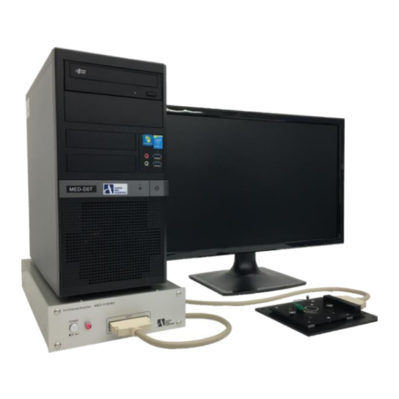
Page 4: Part Names And Functions
Type C The extracellular potential detected at the recording electrodes of the MED probe is amplified 100 times by the MED64-Entry amplifier and converted from an analog to a digital signal by a data acquisition device (National Instruments Corporation) with a built-in PC. -
Page 5: Setup Of The Med64-Entry
A faraday cage or vibration isolation table that is typically necessary for an electrophysiological experiment is not necessary for the MED64-Entry, but the MED64-Entry should be set up on a stable table without vibrations, such as a laboratory desk. A desk of about 100 cm width and 75 cm depth is necessary. -
Page 6: Considerations For The Position Of Devices
In order to ensure sufficient space for an experiment, place the PC on the MED64-Entry amplifier (not essential). Pay attention so as not to damage the housing of the MED64-Entry Amplifier with the legs of the PC. Place the display monitor next to the PC and the MED Connector in front of the monitor. -
Page 7: Connection To The Med64-Entry Amplifier
Make sure that the other side of the lead is connected to the SIGNAL GND terminal of the MED64-Entry Amplifier (to use the conductive cloth tape as an electric shield). -
Page 8: Positioning Of The Terminal Of The Med Connector
➍Connect the PCIe-6463 (0) terminal of the MED64-Entry Amplifier to the PCIe terminal (top) on the back of the PC, using the function cable. ➎Connect the power adaptor to the MED64-Entry Amplifier. 3.4.3. Positioning of the terminal of the MED Connector Place the MED Connector with its output terminal and the 68 pin SCSI cable on the right side. -
Page 9: Electric Shield With Aluminum Foil
Note: Although the MED Connector is made from aluminum, its surface is coated and insulated from the aluminum foil. Make sure that the aluminum foil is grounded to the SIGNAL GND terminal of the MED64-Entry Amplifier when a sheet of aluminum foil is placed under the MED Connector, even if the baseline noise level is within an acceptable range. -
Page 10: Noise Check
Note1: Loosen/tighten both screws little by little at the same time. When the screws are sufficiently loosened/tightened, they can be completely loosened/tightened one by one. If only one screw is completely tightened/loosened without tightening/loosening the other screw, the second screw cannot be inserted perpendicular to the hole. Note2: Do not touch the contact pin of the MED Connector with bare hands. -
Page 11: Data Acquisition By The Control Software "Med16
When the elasticity of the pin decreases, irreversible contact failure occurs. 4. Data acquisition by the control software “MED16” Turn on the power of the amplifier, the PC and the display monitor. Launch the control software by double clicking the MED16 icon on the desktop. -
Page 12: Setting The Data Acquisition Schedule - Record Subpanel
This software has 9 formats predefined for data acquisition assuming a standard experiment and EASY SETTINGS can call up one of these formats (refer to p. 12 “Menus in EASY SETTINGS” for details). When the software starts, Custom is called up from these nine pre-defined conditions. -
Page 13: Creating The Stimulation Pattern - Stimulation Subpanel And Stimulation Pattern Tabs
The maximum input voltage is entered to Max input. When a signal exceeding the set value is input during recording, the set value is acquired as the saturated value. Digitizer resolution is 16 bit in the MED64-Entry, which follows that the resolution of the voltage value is a value obtained by dividing Max input by 2 . - Page 14 Electrode to which the stimulation pattern is applied (it cannot be set for an individual pulse) Pulse # Pulse type Pulse duration The pulse designated by Pulse # or selected Stimulus intensity by a direct click on the STIMULATION Pre and post pulse PATTERN panel is highlighted in red.
-
Page 15: Set Data File Output - File Output Subpanel
EP - culture ….. This menu is provided for recording the evoked response (the spike) in a dissociated neural culture (cultured neural network). A session consisting of 0.1 s data acquisition and 4.9 s waiting time is repeated 100 times. Max input is set at 10,000 uV. -
Page 16: Signal Waveform Panel
4.4. SIGNAL WAVEFORM panel The signal waveform (raw data) is depicted for all 16 electrodes. Select one electrode (in the red frame) by left clicking on the chart of the electrode to show the waveform for that electrode on the BASELINE STABILITY panel. Right clicking on the panel calls up the menu to switch the display of the electrode array pattern or the scope of the display of the axis common to the electrode charts. - Page 17 In EP mode, two perpendicular cursors appear on the signal waveform chart. Use drag & drop to change the position on the X-axis and calculate the minimum value of the raw data between the two perpendicular cursors to obtain the indicator of stability of activity.
-
Page 18: Replaying Data File Output - Function Of Replay Mode
4.6. Replaying data file output – function of replay mode This software has a replay mode to check a recorded data file. Main window of REPLAY mode. As shown in the figure above, the screen looks almost same as that of RECORD mode, except for some differences in the CONTROL PANEL. -
Page 19: Abnormal Noise
Move the responsible device to a position where the noise disappears or unplug the power cable of that device when MED64-Entry is being used. Note: To contact our help desk, select Copy Image by right clicking on SIGNAL WAVEFORM, paste the image of 16 electrode on an image editor such as paint, store in jpg or tif format, and send it to the help desk as an e-mail attachment. - Page 20 - Poor contact between the SCSI cable and the analog input terminal. An example of noise when the contact of the SCSI cable is poor. - The power adaptor or other electronic device (incubator, etc.) is placed close (about 30 to 100 cm) to the terminal of the MED64- Entry Amplifier or the 68 pin SCSI cable.
-
Page 21: Noise Relating To Perfusion
5.3. Noise relating to perfusion - A perfusion pump or its power adaptor is placed close to the amplifier, the MED Connector, or the 68 pin SCSI cable. 25 µV 20 ms An example of magnetic field noise caused by a nearby perfusion pump. Interference occurs in particular electrodes (an example screen of the MED64-Basic to clearly show the disproportionate effect). -
Page 22: Identification Of Cause When A Malfunction Of The Device Is Suspected
Procedure 2: poor contact of cable or lead If poor contact is detected in the output terminal of the MED Connector or the input/output terminal of the MED64-Entry Amplifier, disconnect the SCSI cable completely and connect it again. Check whether the lead or alligator clip connected to the GND terminal has come off or not. -
Page 23: Appendix
6. Appendix 6.1. Specification 6.1.1. MED64-Entry Amplifier [MED-A16HM1] General Information Power DC ±12V Size 3.3 kg Weight W215 x D347 x H74 mm Input Terminal SCSI 68 pin Output Terminal D-sub 68 pin x 2 Amplifier Number of Channels Gain ×100... -
Page 24: Med Connector [Med-C03] And Med Thermo Connector [Med-Cp04]
6.1.3. MED Connector [MED-C03] and MED Thermo Connector [MED-CP04] MED Connector MED Probe Securing Mechanism Screw down Material Aluminum, Gold plate for contact pins Contact Resistance < 30 mΩ (With MED Probe attached) Weight 480 g Size W174 x D150 x H21 mm MED Thermo Connector MED Probe Securing Mechanism Screw down... -
Page 25: Signal Acquisition By The Med64 System
Impedance of electrolyte containing specimen Double layer capacitance Impedance of electrode Ref. elec Rec. elec Input Amplify Input impedance necessary to avoid attenuation of the signal One of unique characteristics of a MEA an “electrical double layer capacitance formed between the interface of the electrodes and the electrolyte. -
Page 26: Stimulus Artifact And Biphasic Stimulation
Mainly the factors listed below influence this process. 1. Typically, the amplitude of the stimulation artifact exceeds the maximum input voltage of the MED64-Entry Amplifier and causes tentative saturation of input. Time is necessary to recover from this condition. This time lag increases in proportion to the stimulator output voltage (Vs). -
Page 27: Stimulus Current Value And Electrolysis
2. A platinum wire is used as additional reference electrodes. When a platinum wire is gripped with a ground wire with a bagworm clip of the MED Connector, the platinum wire functions as an additional reference electrode. The reference electrodes of the MED Probe are positioned at 4 points, and this additional reference electrode of the platinum wire further reduce the total impedance of the reference electrodes and reduce the noise from the perfusion pump and the stimulation artifact. -
Page 28: About The Stimulus Interval
2 mA 200 µA 20 µA 2 µA 0.01 ms 0.1 ms 1 ms 10 ms pulse duration (monophase) 6.2.5. About the stimulus interval The stimulus intensity and stimulation electrode are set in the STIMULATION panel of the MED16 (for details, refer to p. 11 “4.2 Creating stimulation pattern –... - Page 29 This document is subject to change without notice. Reproduction or reprinting of this document, in whole or in part, without the permission of the copyright holder, Alpha MED Scientific Inc., is prohibited. Although every possible care has been taken in preparing this document, the authors assume no responsibility for any errors or omissions in the descriptions in this document, or for any damages that may result from these errors or from the programs or source code described in this document.
Need help?
Do you have a question about the MED64-Entry and is the answer not in the manual?
Questions and answers