Table of Contents
Advertisement
Advertisement
Table of Contents

Summary of Contents for Dometic DDC
- Page 1 DDC Digital Diagnostic Control Operations Manual Revised: 7-10-2017 L-2281...
-
Page 3: Table Of Contents
Dometic Corporation. Every precaution has been taken in the preparation of this manual to insure its accuracy. However, Dometic Corporation assumes no responsibility for errors and omissions. Neither is any liability assumed for damages resulting from the use of this product and information contained herein. -
Page 4: Ddc Controls • Introduction Ddc Features
Overview compressor staging delay or until the fault is cleared. The The DDC Module is designed for use with single or compressor will automatically restart. However, after the multiple stage modular chiller assemblies to provide... -
Page 5: System Outputs
230 VAC and 15 amps @ 115 VAC. freeze fault if the temperature drops below 38°F (3.3°C) in cool mode. DDC generates a HiL high limit fault if the Note: For resistive loads, see specifications for motor load water temperature rises above 125°F in heat mode. Should ratings. - Page 6 The right most LED decimal point will turn on when the compressor or heater is called for. Freeze Stat Protection Open @ 38°F (3.3°C), Close @ 50°F (10°C) NOTE: Freeze Stat is ignored in heat mode. The Freeze Stat will still protect the system even if the microprocessor is not functioning.
-
Page 7: Ddc Controls • Operation
When the circuit breaker is turned on the unit will display the revision code for two (2) seconds. The display will the To program the DDC press the SELECT button to show go blank for one (1) second and remain blank if the mode program item from the following list then press and hold the switch is off. -
Page 8: Program Return Water Temperature
Program Return Water Program Electric Heat Option Temperature With the system on or off press and release the SELECT button to show program item rc or EH. With the system on or off press and release the SELECT button to show program item CSP. Press the SET button until the desired rc reverse cycle heat or EH electric heat selection appears in the display. -
Page 9: Fault Display Codes
Fault Display Codes The following lists the fault mnemonic and the displayed code: 1. High Freon pressure fault = HiP 2. Low Freon pressure fault = LoP 3. Chilled water flow failure = FLO 4. Return Water Sensor failure = Sen 5. -
Page 10: Ddc Control Specifications
DDC Control • Specifications Cooling Set Point Range ..............40°F to 58°F (4.4°C to 14.4°C) Heating Set Point Range ..............95°F to 120°F (35.0°C to 48.9°C) Ambient Temperature Operating Range Displayed ......0°F to 150 F (-17.8°C to 65.6°C) Sensor Accuracy ................± 2°F at 77°F (±1.1°C at 25.0°C) Low Voltage Limit 115 volt units .................... -
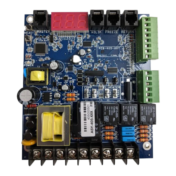
Page 11: Pcb Inputs And Outputs
PCB Inputs and Outputs Transducer wire colors LOW: Red (V+) White (Signal) Black (Ground) HIGH: Red (V+) White (Signal) Black (Ground) L-2281 English... - Page 12 DOMETIC MARINE DIVISION 2000 N. Andrews Ave. Pompano Beach, FL 33069 USA +1 954-973-2477 +1 954-979-4414 Mail marinesales@dometicusa.com 24/7 TECH SUPPORT FOR UNITED STATES AND CANADA 8:00 AM to 5:00 PM Eastern Time: 800-542-2477 After hours and weekends: 888-440-4494 INTERNATIONAL SALES AND SERVICES Europe and the Middle East: +44 (0) 870-330-6101 For all other areas visit our website to find your nearest distributor.
Need help?
Do you have a question about the DDC and is the answer not in the manual?
Questions and answers