Table of Contents
Advertisement
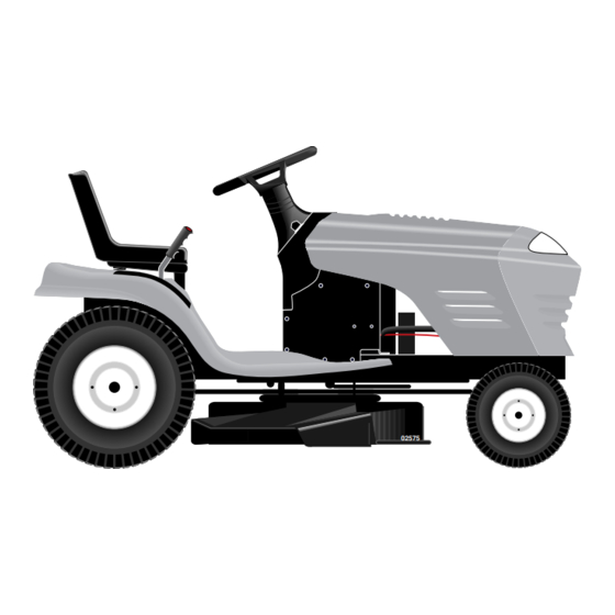
OWNER'S
MANUAL
MODEL NO.
944.602151
Important:
Read and fol low
all Safety Rules
and In struc tions
Be fore Op er at ing
This Equip ment
Sears Canada, Inc., Toronto, Ontario M5B 2B8
00011
15.5 HP
ELECTRIC START
42" MOWER
6 SPEED TRANSAXLE
LAWN TRACTOR
• Assembly
• Operation
• Maintenance
• Service and Adjustments
• Repair Parts
02575
Advertisement
Table of Contents

Related Manuals for Sears CRAFTSMAN 944.602151


Summary of Contents for Sears CRAFTSMAN 944.602151
- Page 1 In struc tions Be fore Op er at ing 42" MOWER This Equip ment 6 SPEED TRANSAXLE LAWN TRACTOR • Assembly • Operation • Maintenance • Service and Adjustments • Repair Parts Sears Canada, Inc., Toronto, Ontario M5B 2B8...
-
Page 2: Safety Rules
SAFETY RULES Safe Operation Practices for Ride-On Mowers IMPORTANT: THIS CUTTING MACHINE IS CAPABLE OF AMPUTATING HANDS AND FEET AND THROW ING OBJECTS. FAILURE TO OBSERVE THE FOLLOWING SAFETY INSTRUCTIONS COULD RESULT IN SERIOUS INJURY OR DEATH. I. GENERAL OPERATION DO NOT: •... -
Page 3: Table Of Contents
SAFETY RULES Safe Operation Practices for Ride-On Mowers • Be sure the area is clear of other people before mowing. Stop machine if anyone enters the area. WARNING: Do not coast down a hill in neu- • Never carry passengers or children even with the blades tral, you may lose control of the trac tor. -
Page 4: Product Specifications
LIMITED TWO (2) YEAR WARRANTY ON CRAFTSMAN TRACTOR (RIDING EQUIPMENT) For two (2) years from date of purchase Sears Canada, Inc. will repair or replace at Sears option free of charge parts which are defective as a result of material or workmanship. - Page 5 CONTENTS OF HARDWARE PACK Battery Steering Wheel (2) Hex Bolts (2) Keps Nut 1/4-20 1/4-20 x 3/4 Seat Steering Wheel Insert Steering Extension Shaft Steering Sleeve (1) Washer 17/32 x 1-3/16 x 12 Gauge (1) Knob Steering Wheel Adapter (1) Oil Drain Tube For Future Use Keys Slope Sheet...
-
Page 6: Assembly
ASSEMBLY Your new tractor has been assembled at the factory with exception of those parts left unassembled for shipping purposes. To ensure safe and proper operation of your tractor all parts and hardware you assemble must be tightened securely. Use the correct tools as necessary to insure proper tightness. - Page 7 ASSEMBLY HOW TO SET UP YOUR TRACTOR INSTALL SEAT (See Fig. 4) Adjust seat before tightening adjustment knob. CONNECT BATTERY (See Figs. 2 and 3) • Remove adjustment knob and fl at washer securing seat to cardboard packing and set aside for assembly CAUTION: Do not short battery ter- of seat to tractor.
- Page 8 ASSEMBLY CHECK TIRE PRESSURE TO ROLL TRACTOR OFF SKID (See Op- er a tion section, for location and func tion of The tires on your tractor were overinfl ated at the factory con trols) for shipping purposes. Correct tire pressure is important for best cutting performance.
-
Page 9: Operation
OPERATION These symbols may appear on your tractor or in literature supplied with the product. Learn and understand their mean- ing. IGNITION FAST SLOW REVERSE HIGH NEUTRAL CHOKE LIGHTS ON ENGINE START ENGINE ON PARKING BRAKE ENGINE OFF PARKING BRAKE PARKING BRAKE LOCKED UNLOCKED... - Page 10 OPERATION KNOW YOUR TRACTOR READ THIS OWNER'S MANUAL AND SAFETY RULES BEFORE OPERATING YOUR TRACTOR Compare the illustrations with your tractor to familiarize yourself with the locations of various controls and ad just ments. Save this manual for future reference. IGNITION LIGHT SWITCH SWITCH...
- Page 11 OPERATION The operation of any tractor can result in foreign objects thrown into the eyes, which can result in severe eye dam age. Always wear safety glass es or eye shields while op- erating your tractor or per form ing any adjustments or repairs. We rec om mend a wide vision safety mask over spectacles or stan dard safety glasses.
- Page 12 OPERATION NOTE: To protect hood from damage when transporting TO OPERATE MOWER (See Fig. 7) your tractor on a truck or a trailer, be sure hood is closed Your tractor is equipped with an operator presence sensing and secured to tractor. Use an appropriate means of tying switch.
- Page 13 OPERATION TO START ENGINE (See Fig. 5) MOWING TIPS When starting the engine for the fi rst time or if the engine • Mower should be properly leveled for best mowing per- has run out of fuel, it will take extra cranking time to move for mance.
-
Page 14: Maintenance Schedule
MAINTENANCE MAINTENANCE SCHEDULE FILL IN DATES AS YOU COMPLETE REGULAR SERVICE SERVICE DATES Check Brake Operation Check Tire Pressure Check Operator Presence and Interlock Systems Check for Loose Fasteners Sharpen/Replace Mower Blades Lubrication Chart Check Battery Level Clean Battery and Terminals Check Transaxle Cooling Check V-Belts Check Engine Oil Level... -
Page 15: Maintenance
MAINTENANCE TRACTOR MANDREL TRAILING ASSEMBLY BLADE EDGE UP Always observe safety rules when performing any main- te nance. CENTER HOLE BRAKE OPERATION FLAT WASHER If tractor requires more than six (6) feet stopping distance at high speed in highest gear, then brake must be adjusted. (See “TO ADJUST BRAKE”... - Page 16 MAINTENANCE TO CLEAN BATTERY AND TERMINALS Change the oil after every 25 hours of operation or at least once a year if the tractor is not used for 25 hours in one Corrosion and dirt on the battery and terminals can cause year.
- Page 17 MAINTENANCE ENGINE COOLING FINS (See Fig. 13) COVER KNOB Remove any dust, dirt or oil from engine cooling fi ns to prevent engine damage from overheating. • Remove oil fi ll cap/dipstick. CAR TRIDGE • Remove hex bolts from blower housing and lift housing COVER off engine.
-
Page 18: Service And Adjustments
SERVICE AND ADJUSTMENTS WARNING: TO AVOID SE RI OUS IN JU RY, BEFORE PERFORMING ANY SERVICE OR ADJUST- MENTS: • Depress clutch/brake pedal fully and set parking brake. • Place gearshift lever in neutral (N) position. • Place attachment clutch in “DISENGAGED” position. •... - Page 19 SERVICE AND ADJUSTMENTS • Connect suspension arms to rear deck brackets and FRONT-TO-BACK ADJUSTMENT (See Figs. 19 and 20) secure with retainer springs. IMPORTANT: DECK MUST BE LEVEL SIDE-TO-SIDE. IF THE • Connect anti-swaybar to chassis bracket and secure FOLLOWING FRONT-TO-BACK ADJUSTMENT IS NECESSARY, with retainer spring.
- Page 20 SERVICE AND ADJUSTMENTS TO REPLACE MOWER BLADE DRIVE BELT WITH PARKING BRAKE “ENGAGED” (See Fig. 21) The mower blade drive belt may be replaced without tools. Park the tractor on level surface. Engage parking brake. 1-1/2" BELT REMOVAL - • Remove mower from tractor (See “TO REMOVE MOW ER”...
- Page 21 SERVICE AND ADJUSTMENTS FRONT WHEEL TOE-IN/CAMBER ENGINE The front wheel toe-in and camber are not adjustable on PULLEY your tractor. If damage has occurred to affect the front wheel toe-in or camber, contact your nearest authorized CLUTCHING IDLER service center/department. TO REMOVE WHEEL FOR REPAIRS CENTER SPAN (See Fig.
- Page 22 SERVICE AND ADJUSTMENTS TO ATTACH JUMPER CABLES - • Connect one end of the RED cable to the POSITIVE (+) terminal of each battery(A-B), taking care not to short against tractor chassis. • Connect one end of the BLACK ca ble to the NEGA TIVE (-) terminal (C) of fully charged battery.
- Page 23 SERVICE AND ADJUSTMENTS TO AD JUST CARBURETOR (See Fig. 29 ) IDLE SPEED SCREW NOTE: The carburetor on this engine is low emission. It is equipped with an idle fuel adjusting needle with a lim- iter cap, which allows some adjustment within the limits THROTTLE LEVER al lowed by the cap.
-
Page 24: Storage
STORAGE Immediately prepare your tractor for storage at the end ENGINE of the season or if the tractor will not be used for 30 days or more. FUEL SYSTEM IMPORTANT: IT IS IMPORTANT TO PREVENT GUM DEPOSITS WARNING: Never store the trac tor with FROM FORMING IN ES SEN TIAL FUEL SYSTEM PARTS SUCH gas o line in the tank inside a building AS CARBURETOR, FUEL FIL TER, FUEL HOSE, OR TANK... -
Page 25: Trou Ble Shoot Ing
TROUBLESHOOTING POINTS PROBLEM CAUSE CORRECTION Will not start Out of fuel. Fill fuel tank. Engine not “CHOKED” properly. See “TO START ENGINE” in Operation section. Engine fl ooded. 3. Wait several minutes before attempting to start. Bad spark plug. Replace spark plug. Dirty air fi... - Page 26 TROUBLESHOOTING POINTS PROBLEM CAUSE CORRECTION Engine continues to run Faulty operator-safety presence control system. Check wiring, switches and connections. If not when operator leaves seat corrected, contact an authorized service center/ with attachment clutch department. engaged Poor cut - uneven 1.
- Page 27 TRACTOR - - MODEL NUMBER 944.602151 SCHEMATIC BLACK BATTERY FUSE STARTER AMMETER (OPTIONAL) BLACK WHITE SOLENOID CLUTCH / BRAKE (PEDAL UP) WHITE SEAT SWITCH IGNITION (NOT OCCUPIED) SWITCH WHITE BLACK BLACK BLACK BLACK ATT'MENT CLUTCH GROUNDING (CLUTCH OFF) BLACK CONNECTOR HOUR METER (OPTIONAL)
-
Page 28: Repair Parts - Tractor
REPAIR PARTS TRACTOR - - MODEL NUMBER 944.602151 ELECTRICAL D .C... - Page 29 REPAIR PARTS TRACTOR - - MODEL NUMBER 944.602151 ELECTRICAL PART DESCRIPTION 163465 Battery 12 Volt 28 Amp 74760412 Bolt Hex Hd 1/4-20unc X 3/4 176689 Case Battery 176138 Switch Interlock Push-In 175688 Harness Asm Light W/4152J 4152J Bulb Light #1156 4799J Cable Battery 6 Ga 11"red 146147...
- Page 30 REPAIR PARTS TRACTOR - - MODEL NUMBER 944.602151 CHASSIS AND ENCLOSURES...
- Page 31 REPAIR PARTS TRACTOR - - MODEL NUMBER 944.602151 CHASSIS AND ENCLOSURES PART DESCRIPTION 174619 Chassis 176554 Drawbar 17060612 Screw 3/8-16x3/4 155272 Bumper Hood/Dash 168337X011 Dash STD533710 Bolt Carriage 3/8-16 x 1 174996 Panel Dash Lh 145660 Clip Tinnerman 172105X010 Panel Dash Rh 17490608 Screw Thdrol 3/8-16 x 1/2 144983X558 Hood...
- Page 32 REPAIR PARTS TRACTOR - - MODEL NUMBER 944.602151 DRIVE 52 30...
- Page 33 REPAIR PARTS TRACTOR - - MODEL NUMBER 944.602151 DRIVE KEY PART KEY PART NO. NO. DESCRIPTION NO. NO. DESCRIPTION - - - - - - - - - Transaxle (See Breakdown) Peer- 71170764 Bolt Hex less 206-545C STD55143 Washer Lock Hvy Hlcl Spr 7/16 146682 Spring Return Brake T/a Zinc 154778...
- Page 34 REPAIR PARTS TRACTOR - - MODEL NUMBER 944.602151 STEERING ASSEMBLY...
- Page 35 REPAIR PARTS TRACTOR - - MODEL NUMBER 944.602151 STEERING ASSEMBLY PART DESCRIPTION 139768 Wheel Steering 175131 Axle Asm Welded LT/STL 169840 Spindle Asm LH 169839 Spindle Asm RH 6266H Bearing Race Thrust Harden 121748X Washer 25/32 X 1-5/8 X 16 Ga 19272016 Washer 27/32 X 1-1/4 X 16 Ga 12000029...
- Page 36 REPAIR PARTS TRACTOR - - MODEL NUMBER 944.602151 SEAT ASSEMBLY PART PART DESCRIPTION DESCRIPTION 140122 Seat 121248X Bushing Snap Blk Nyl 50 Id 140551 Bracket Pivot Seat 8 720 72050412 Bolt Rdhd Sqnk 1/4-20x1-1/2 71110616 Bolt Fin Hex 3/8-16unc X 1 134300 Spacer Split 28x 96 Yel Zinc 19131610...
- Page 37 REPAIR PARTS TRACTOR - - MODEL NUMBER 944.602151 DECALS PART PART DESCRIPTION DESCRIPTION 156369 Decal Fend STLT Oper 179128 Decal Mower "B" "42" 181563 Decal Engine 160396 Decal V-Belt Schematic 171697 Decal Hood LH 149517 Decal Bat Dan/Psn 171696 Decal Hood RH 182105 Decal Replacement Parts 146046...
- Page 38 REPAIR PARTS TRACTOR - - MODEL NUMBER 944.602151 ENGINE OPTIONAL EQUIPMENT Spark Arrester PART PART DESCRIPTION DESCRIPTION 137040 Line Fuel 20" 170545 Control Throt /Ch 148315 Plug Drain Oil Easy 17720410 Screw Hex Thd Cut 1/4-20x5/8 T 124028X Bushing Snap Nyl Blk Fuel Line - - - - - - Engine (See Breakdown) 17670412...
- Page 39 REPAIR PARTS TRACTOR - - MODEL NUMBER 944.602151 MOWER LIFT 17 18 20 PART PART DESCRIPTION DESCRIPTION STD624008 Retainer Spring 159460 Wire Asm Inner W/Plunger 173288 Link Front 159471 Shaft Asm Lift 73350800 Nut Jam Hex 1/2-13 Unc 105767X Pin Groove 175689 Trunnion Blk Zinc STD581062 E Ring...
- Page 40 REPAIR PARTS TRACTOR - - MODEL NUMBER 944.602151 MOWER DECK 153 154...
- Page 41 REPAIR PARTS TRACTOR - - MODEL NUMBER 944.602151 MOWER DECK PART PART DESCRIPTION DESCRIPTION Gauge 165892 Mower Deck Assembly, 42” STD541437 Nut Crownlock 3/8-16 UNC STD533107 Bolt RDHD SQNK 5/16-18 Unc x 140088 Guard, Mandrel, L.H. STD624003 Retainer 138017 Bracket Assembly,Sway Bar, 137729 Screw, Thd.
- Page 42 REPAIR PARTS TRACTOR - - MODEL NUMBER 944.602151 PEERLESS TRANSAXLE - MODEL NUMBER 206-545C...
- Page 43 REPAIR PARTS TRACTOR - - MODEL NUMBER 944.602151 PEERLESS TRANSAXLE - MODEL NUMBER 206-545C PART DESCRIPTION DESCRIPTION 790079 Brake Lever 772147 Transaxle Cover 792073A Screw 1/4 - 20 x 1-1 /4” 792085A Screw 1/4 - 20 x 2 1/4” 780086A Needle Bearing 5/8”...
-
Page 44: Repair Parts - Engine
REPAIR PARTS TRACTOR - - MODEL NUMBER 944.602151 BRIGGS & STRATTON ENGINE - MODEL NUMBER 28U707, TYPE NUMBER1112-E1 1022 1023 1026 1022 186A 1034 1029 1095 VALVE GASKET SET 1022 REQUIRES SPECIAL TOOLS TO INSTALL. SEE REPAIR INSTRUCTION MANUAL. 1019 LABEL KIT 1058 OWNER'S MANUAL... - Page 45 REPAIR PARTS TRACTOR - - MODEL NUMBER 944.602151 BRIGGS & STRATTON ENGINE - MODEL NUMBER 28U707, TYPE NUMBER1112-E1 REQUIRES SPECIAL TOOLS TO INSTALL. SEE REPAIR INSTRUCTION MANUAL. 141A 108A 634A 1091 1127 121 CARBURETOR OVERHAUL KIT 358 ENGINE GASKET SET 634A 1022 977 CARBURETOR GASKET SET...
- Page 46 REPAIR PARTS TRACTOR - - MODEL NUMBER 944.602151 BRIGGS & STRATTON ENGINE - MODEL NUMBER 28U707, TYPE NUMBER1112-E1 309A 801A 510A 729A 544A 783A 697A 803A 802A 1083 311A 1083A 305A NOTE: For Replacement Starter Motor, See Reference 309. 789A 1119 1005 1051...
- Page 47 REPAIR PARTS TRACTOR - - MODEL NUMBER 944.602151 BRIGGS & STRATTON ENGINE - MODEL NUMBER 28U707, TYPE NUMBER1112-E1 NIKKI 125A 141B 131A 108B 121A CARBURETOR OVERHAUL KIT 130A 231A 276A 987A 104A 133A 104A 127A 117A 105A 987A 127A 975A 137A 231A 137A...
- Page 48 REPAIR PARTS TRACTOR - - MODEL NUMBER 944.602151 BRIGGS & STRATTON ENGINE - MODEL NUMBER 28U707, TYPE NUMBER1112-E1 PART PART DESCRIPTION DESCRIPTION 496412 Cylinder Assembly 691155 Screw (Rotating Screen) 399265 Kit-Bushing/Seal 690582 Washer (Flywheel) 391086 • Seal-Oil (Magneto Side) 690661 Screw (Flywheel Guard) 494238 Sump-Engine...
- Page 49 REPAIR PARTS TRACTOR - - MODEL NUMBER 944.602151 BRIGGS & STRATTON ENGINE - MODEL NUMBER 28U707, TYPE NUMBER1112-E1 PART PART DESCRIPTION DESCRIPTION 691714 Link-Counterweight 231A 690718 Ø Screw (Choke Valve) 692423 Counterweight 691842 Spring-Governor Link 691239 Pin-Counterweight 691843 Cap-Valve 691096 Screw (Counterweight) 394358 Filter-Fuel...
- Page 50 SERVICE NOTES...
- Page 52 PRINTED IN U.S.A. 183266 Rev. 2 10.02.02 TR...
Need help?
Do you have a question about the CRAFTSMAN 944.602151 and is the answer not in the manual?
Questions and answers
In Figure 22 it shows a spring. I need a replacement spring as mine broke. I don't know what it's called or where to get it. Can you help me?
You can find a replacement spring under part number 146682, which is listed as the "Spring Return Brake T/a Zinc" for CRAFTSMAN model 944.602151.
This answer is automatically generated