Table of Contents
Advertisement
Quick Links
TM
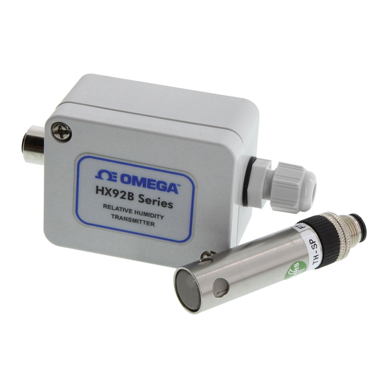
HX92B(*)-D duct mount
transmitter shown smaller
than actual size
Relative Humidity Transmitters
TH-SP short
probe with M12
connector
HX92B wall mount shown
larger than actual size
User' s Gui d e
Shop online
omega.com
e-mail: info@omega.com
For the latest product
www.omega.com/en-
TH-RP remote
probe with 3 m
(10') cable
and M12
connector
HX92B SERIES
at
manuals:
us/pdf-manuals
Advertisement
Table of Contents

Related Manuals for Omega Engineering HX92B Series

Summary of Contents for Omega Engineering HX92B Series
- Page 1 Shop online omega.com e-mail: info@omega.com For the latest product manuals: www.omega.com/en- us/pdf-manuals TH-RP remote probe with 3 m (10') cable and M12 connector HX92B(*)-D duct mount transmitter shown smaller than actual size HX92B SERIES Relative Humidity Transmitters...
- Page 2 Omega Engineering, Inc: 800 Connecticut Ave. Suite 5N01, Norwalk, CT 06854, USA Toll-Free: 1-800-826-6342 (USA & Canada only) C ustomer Service: 1-800-622-2378 (USA & Canada only) Engineering Service: 1-800-872-9436 (USA & Canada only) Tel: (203) 359-1660 Fax: (203) 359-7700 e-mail: info@omega.com...
-
Page 3: Table Of Contents
HX92B Relative Humidity Transmitters Table of Contents Section Page General Description ................... 1-1 Unpacking ....................2-1 Theory of Operation and Electrical Connection ........3-1 3.1.1 Theory Operation ................3-1 Mounting ..................... 4-1 Relative Humidity Output Calculations ..........5-1 Calibration ....................6-1 Maintenance .................... - Page 4 HX92B Relative Humidity Transmitters List of Figures Figure Description Page Figure 1-1 Transmitter Internal Diagram ............1-1 Figure 3-1 Voltage Output Connection Diagram ........3-1 Figure 3-2 Current Output Connection Diagram ........3-2 Figure 4-1 Wall Mount Model Dimensions ........... 4-1 Figure 4-2 Duct Mount Model Dimensions ..........
-
Page 5: General Description
The OMEGA ® HX92B Series Relative Humidity Transmitter provides a linearized and temperature compensated output signal of 4 to 20mA, 0 to 1 Vdc, 0 to 5 Vdc or 0 to 10 Vdc depending upon the model selected. The output signals have been calibrated and scaled 0 to 100% Relative Humidity output scale. -
Page 6: Unpacking
The carrier will not honor any damage claims unless all shipping material is saved for inspection. After examining and removing contents, save packing material and carton in the event reshipment is necessary. The following items are supplied in the box with your HX92B Series transmitter. • HX92B Series Quick start Manual, MQS-5339 (1 ea.) • #6 Wall Anchor and #6 Mounting Screw (2 ea.) - Page 7 Unpacking 2.1 HX92B available models and functional description Model number Description HX92BC Wall Mount Relative Humidity Transmitter, 4 to 20mA. HX92BV0 Wall Mount Relative Humidity Transmitter, 0 to 1 volt. HX92BV1 Wall Mount Relative Humidity Transmitter, 0 to 5 volt. HX92BV2 Wall Mount Relative Humidity Transmitter, 0 to 10 volt.
-
Page 8: Theory Of Operation And Electrical Connection
Theory of Operation and Electrical Connection Section 3 – Theory of Operation and Electrical Connection 3.1.1 Theory of Operation A 4 to 20 mA loop is a series loop in which a transmitter will vary the current flow depending on the input to the transmitter. In the HX92B the amount of the current allowed to flow in the loop will vary depending on the relative humidity being measured by the sensor. Some advantages of a current output over a voltage output is that the signal measured is less susceptible to electrical noise interference, and the loop can support more than one measuring instrument as long as the maximum loop resistance is not exceeded. -
Page 9: Figure 3-2 Current Output Connection Diagram
Theory of Operation and Electrical Connection – POWER IN – R/H OUTPUT POWER SUPPLY 4 - 20 MA 9 -30 Vdc MAX. CHASSIS Figure 3-2. Current Output Connection Diagram... -
Page 10: Mounting
Mounting Section 4 - Mounting The HX92B transmitters are designed for wall, duct or remote probe mounting depending upon the model. Plastic wall anchors and mounting screws are included with Wall Mount and Remote Probe models. A duct mounting kit is included with Duct Mount models. -
Page 11: Figure 4-2 Duct Mount Model Dimensions
Mounting 50.0 (1.97) 34.8 (1.37) 15.8 (0.59) DIMENSIONS mm (in) 20.6 (0.81) Ø16.0 Ø(0.63) 65.0 (2.56) 128.0 (5.04) 163.3 (6.43) Figure 4-2. Duct Mount Model Dimensions 127.3 (5.01) 304.8 cm (10') (2.56) Ø17.3 Ø(0.68) (1.97) 54.1 (2.13) DIMENSIONS mm (in) Figure 4-3 Remote Probe Model Dimensions... -
Page 12: Relative Humidity Output Calculations
Relative Humidity Output Calculations Section 5 - Relative Humidity Output Calculations To calculate % relative humidity by measuring the current or voltage output, use the following formulas: For current output: %RH = (Current measured in milliamps – 4) ÷ 0.16 Where: 4 = offset current in mA. - Page 13 Relative Humidity Output Calculations RH Measured Vs Output Reading Output % Relative Humidity Current 0 to 1 Volt 0 to 5 Volt 0 to 10 Volt (mA) (Vdc) (Vdc) (Vdc) 4.16 0.01 0.05 0.10 4.32 0.02 0.10 0.20 4.48 0.03 0.15 0.30 4.64...
-
Page 14: Calibration
Calibration Section 6 - Calibration Your transmitter has been digitally calibrated and tested to meet or exceed the specifications outlined in this manual in our factory. The transmitter must be sent back to the factory for any re-calibration request. -
Page 15: Maintenance
Maintenance Section 7 - Maintenance The sensor probe can be replaced quickly for Wall Mount and Remote Probe models. Procedure to replace the sensor probe: a. Loosen the securing nut, and pull the sensor probe out. b. I nsert the new sensor probe to the M12 connector, and tighten the securing nut to secure the connection. -
Page 16: Specifications
Specifications Section 8 - Specifications 0 to 100% Measuring Range: ±2.5% from 20 to 80% RH, ±3.5% from 5 to 20% Accuracy Range: and 80 to 95% RH; ±4% from 0 to 5% and 95 to 100% RH ±1% Hysteresis: ±0.1% Repeatability: Resolution:... - Page 17 WARRANTY/DISCLAIMER OMEGA ENGINEERING, INC. warrants this unit to be free of defects in materials and workmanship for a period of 13 months from date of purchase. OMEGA’s WARRANTY adds an additional one (1) month grace period to the normal one (1) year product warranty to cover handling and shipping time. This ensures that OMEGA’s customers receive maximum coverage on each product.
- Page 18 Where Do I Find Everything I Need for Process Measurement and Control? OMEGA…Of Course! Shop online at omega.com TEMPERATURE M U Thermocouple, RTD & Thermistor Probes, Connectors, Panels & Assemblies M U Wire: Thermocouple, RTD & Thermistor M U Calibrators & Ice Point References M U Recorders, Controllers &...
Need help?
Do you have a question about the HX92B Series and is the answer not in the manual?
Questions and answers