
Related Manuals for Huazheng HZ-ATU601


Summary of Contents for Huazheng HZ-ATU601
- Page 1 HZ-ATU601 Digital Ultrasonic Flaw Detector Huazheng Electric Manufacturing (Baoding) Co., Ltd...
- Page 2 (0312) 6775656 to tell you to ser ve you at all times- Baoding Huazheng Elect ric Manufact uring Co. , Lt d. , our company will def initely make you satisf ied !
-
Page 3: Table Of Contents
Contents I.Overview............................1 II.Attention............................1 III.Preface............................1 IV.Instrument Introduction....................... 6 V.System Parameter Settings...................... 16 VI.Inspection Operation Example....................37 VII.Assistant Function........................55 VIII.Testing Accuracy and Defect Evaluation................59 IX.Fault Diagnosis and Elimination....................61... -
Page 4: I.overview
I.Overview This instrument is a collection of portable and fully-digital ultrasonic flaw detector. The two models in the series–high version and low version–all have the capacity to detect, localize and evaluate various defects in metals with rapidity and precision. Particularly, it is highly effective in the detection of welds, cracks, inclusions, and metal porosity in a non-destructive manner that is suitable for laboratory or project site environments. - Page 5 configurations. Users can refer to the operating manual according to their specific model. Prior to first-use, please check carefully whether the instruments and accessories are consistent with the packing list – if not, please contact us. Please also carefully read the operating manual to ensure that you understand the rights and services you may be entitled to.
- Page 6 Real-time sample: high speed ADC, wave detail fully displayed. Rectification: full, positive, negative, reflective. Gate: dual-gate, support time gate and sound path gate, echo capture automatically. Gain: Multi-grade adjustable, basic gain, scan gain, compensation gain, support locked gain and auto gain; ◇Alarm function: beep alarm and flash alarm.
- Page 7 Defect qualitative analysis: real-time estimates and judgements of envelope waveform. Curved surface correction: automatic correction and conversion of curved surfaces (only high version) Broadening function: user-adjustable ability to broaden the waveform selection. Echo code: different echoes distinguished by different colors (only high version) 1.2Specifications The specifications of the instruments are shown in the Table 1.
- Page 8 Sensitivity >62 dB(depth: 200 mm, flat-bottom hole Ф2) Resolution >40 dB Linearity Reject 0~80%(digital reject) Vertical Linearity Error ≤3% Horizontal Linearity Error ≤0.1% Dynamic Range ≥32 dB Pulse Energy Fixed Multi-grades adjustable( 100V, 250V, 350V, 450V) Pulse Width 50~1000 ns Auto match (50~1000 ns); sharp pulse Environment Temperature -10oC~﹢50 oC Environment...
-
Page 9: Iv.instrument Introduction
1.4Caution ◇Refrain from powering on and off repeatedly – please wait for 5s before powering on again. ◇Avoid strong vibrations, impacts or strong magnetic fields. ◇Do not leave the detector in high temperature, high humidity or corrosive gas environments. ◇Do not overexert operation of detector keys, and minimise operation of keys with oily or muddy hands. - Page 10 indicating that the charger is working properly. When the DC charger is then plugged into the detector, the power indicator lamp will turn red and the detector can be used. Note: Please use a stable and reliable AC power supply between 100-240V at 50Hz to avoid damaging to the charger, lithium-ion battery or detector.
- Page 11 ◇Please use the provided charger when charging the battery to avoid damage to the battery (note that a damaged battery from inappropriate charging is not covered by our warranty). ◇All lithium-ion batteries self-discharge over time. To preserve the detector’s inner components and battery life, turn on and recharge the detector for one to two hours at least once a month.
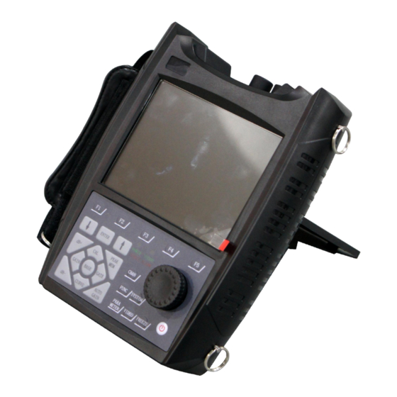
- Page 12 Fig.2-1 Schematic of the unit (1) Keypad (2) Hand-belt (3) TFT screen (4) Power indicator (5) Alarm indicator (6) Digital rotating wheel (7) Supporter (8) USB port (9) Reset and power-off port (10) Charging port (11) Receiving port (12) Receiving/transmitting port (13) Protective shell 2.2.1Indicator Alarm indicator: the alarm indicator lamp flashes to give a warning that the echo peak...
- Page 13 connected to the transmitting port, and the receiving probe cable is connected to the receiving port using dual-crystal probe. Note: The quality of the probe cable may affect testing outcomes. Additionally, If the transmitting probe cable and receiving probe cable are misconnected while using a dual-crystal probe, there may be echo loss or waveform disorder.
- Page 14 Fig.2-2 Main interface and status bar of the Echo GUI Parameters Interface PARAMETER UNLO PARA-LOCK …………………………………………… ………………………………………… EXIT … …… © ………………………………………… …… ………………………………………… …… VELO ………………………………………… 5920 ……………………………………………… CITY …… 0.0mm ………………………………………… ……………………………………………… …… 15.0mm ………………………………………… ……………………………………………… 25 …… ………………………………………………...
- Page 15 altered using the same method. 2.4Keypad The keypad is designed with two modes of operation: key input or the digital rotating wheel, as shown in Fig.2-4. All control commands can be completed with keys or the rotating wheel. Key input operation: The keys of the keypad can be grouped into four regions.
- Page 16 of the shortcut keys to help the user complete the testing process quickly: Freeze: Press FREEZE to immediately freeze the displayed waveform and data seen on the screen. To unfreeze waveform and data, simply press FREEZE again. This key also works to freeze echoes when applicable. Note that the displayed waveform and data must be unfrozen before loading saved waveforms.
- Page 17 turned on again. 2.6 Menu Structure BASE MAIN RANGE GATE GAIN READING ECHO MENU SUB-MENU RANGE SELECT dB-BASIC GATEMODE RECTIFY VELOCITY START dB-STEP TRIGGER REJECT DDELAY WIDTH dB-SCAN MEMMODE FILL PDELAY THRESH dB-COMP EXPAND COLORLEG MAIN PROBE CALI ANGLE PULSER SETUP MENU SUB-MENU...
- Page 18 MENU SUB-MENU DRAW EDIT H-AVG DISPLAY RANGE RANGE M-AVG REF-SIZE TYPE POINT POINT L-AVG PSIZE FITTING GSTART GSTART ALM-BASE PFREQ REMOVE FUNC MAIN SCAN WELD DIAMETER CRACK SURFACE MENU SUB-MENU BSCAN WELD DIAMETER CRACK SURFACE SETUP GSTART IN-D SPPED TOWELD PSIZE OUT-D ASCAN...
-
Page 19: V.system Parameter Settings
MENU SUB-MENU CHANNEL WAVEFORM VIDEO RMCHAN SAVE SAVE RECORD REWAVE SAVE AS LOAD PLAY RMVIDEO REMOVE REMOVE REMOVE FACTORY V.System Parameter Settings 3.1Language The detector supports both Chinese and English (English is default in this version). To switch, operate as follows: 1.Press System to enter the system function menu and press F1 to select the “DISPLAY”... - Page 20 3.3Color Theme The color theme of the GUI can be set to the operator’s preference. To adjust the color theme, operate as follows: 1.Press SYSTEM to enter the system function menu and press F1 to select the “DISPLAY” main-menu; 2.Press [↑] or [↓] to select the THEME sub-menu and then roll the rotating wheel to the background color (16 kinds of color themes are available).
- Page 21 2.Press [↑] or [↓] to select UNITS sub-menu and then roll the rotating wheel to change between mm or inch; 3.Press [↑] or [↓] to select HSCALE sub-menu and then roll the rotating wheel to change the horizontal scale to depth, scale, time or S-path;; 4.Press [↑] or [↓] to select GRID sub-menu and then roll the rotating wheel to change the grid display on or off.
- Page 22 either ABOVE G, BELOW G, ABOVE C or BELOW C is registered (this can be selected in TYPE). The detector will always flash the LED when the battery is empty. TYPE: Notifications can be set for ABOVE G, BELOW G, ABOVE C and BELOW C. ABOVE G: when the echo amplitude in the gate is higher than gate height.
- Page 23 wheel to adjust date and time. 3.8Factory Reset 1.Press SYSTEM twice to enter the second system function menu and then press F4 to select the “MGMT” main-menu; 2.Press [↑] or [↓] to select the FACTORY sub-menu, press ENTER, and the screen will prompt “RESTORE FACTORY SETTING? PRESS ’OK’! ”.
- Page 24 2.Use [↓] or [↑] to select sub-menu “RANGE”, then roll the rotating wheel to adjust range. 4.2Gate operation The gate can be modified in the following aspects: SELECT (gate selection), START (gate start), WIDTH (gate width) and THRESH (gate threshold ), operations are as follows: To enter the gate sub-menu, first press GATE (or BASE), and then select “GATES”...
- Page 25 To adjust gate width, use [↓] or [↑] to select “WIDTH”, and then roll the rotating wheel to select desired width. The same process can be used to adjust gate threshold (select “THRESH” instead of “WIDTH”). Gate threshold refers to percentage relative to the full screen of the echo display area. It can be adjusted from 0% to 80%.
- Page 26 Automatic gain adjustment operation: Change the gain value of the auto gain first. Operation: Press CAL, select “SETUP” by pressing F5, use [↓] or [↑] to select “AUTO-80”, and adjust the value to the required gain. Then press AUTO GAIN, and the detector will amplify the echo according to the set gain.
- Page 27 Press BASE to enter into the base function group menu, and select “READING” by pressing F4. Use [↓] or [↑] to select “GATEMODE”, then roll the rotating wheel to select “SINGLE” or “DUAL”. The same process can be used to open or close the TRIGGER function. The same process can be used to select peak memory, echo envelope or shut off the memory function (MEMMODE).
- Page 28 4.6.2 Echo envelope Echo envelope records the highest value of the echo and the horizontal location of the probe at this point. Press PEAK MEM key when scanning, if the aforementioned symbol at the bottom-right corner of the screen appears, it means that the peak memory function is activated. Press PEAK MEM again and the symbol at the bottom-right corner of the screen changes to, indicating that the echo envelope function is activated.
- Page 29 Use [↓] or [↑] to select the “PROBE” sub-menu, and roll the rotating wheel to select between NORMAL, ANGLE, DUAL and TRANS. The detector should be re-calibrated whenever probe type is changed. Probe type Icon Normal Angle Dual Trans FREQ, FILTER and PSIZE can be adjusted using the same operation as PROBE and selecting the respective sub-menu Note: Input FREQ and PSIZE according to the nominal value of the probe before testing.
- Page 30 5. Data Storage and Communication 5.1 Channel When completing outdoor inspections, it is often necessary to use several probes to inspect multiple workpieces. The channel function in this detector allows users to conveniently pre-test and save multiple inspection setups that can then be immediately loaded without further adjustment when testing outdoors.
- Page 31 selected channel, and regard these parameters as working parameters. SAVE: All set parameters of the system will be saved in the current channel. If the current channel already contains data, the set parameters cannot be saved. Please select another channel or clear the filled channel to save the set parameters. SAVE AS: The set parameters of the system will be saved into an available empty channel.
- Page 32 “LOAD” sub-menu also includes +CHAN and –CHAN functions that can be accessed by turning the rotating wheel in the sub-menu. If –CHAN is selected, the system will automatically read the parameters in the selected XXX waveform and set these parameters as the working parameters. These channel parameters can then be saved in the “CHANNEL”...
- Page 33 can still be adjusted during recording and whilst the probe is in operation. To stop recording, select the “RECORD” sub-menu and press ENTER (or directly press VIDEO) to complete recording. When recording is over, the detector will prompt “FINISH RECORD” and subsequent to this the recording duration and will disa ppear.
- Page 34 2.Right click “Digital Ultrasonic Flaw Detector”, select “Driver Software Update”, and choose the second “Browse my computer for driver software”. 3. Ensure that the supplied USB software flash stick is inserted, then click “Browse...” and select the location of driver software found in the USB flash stick (according to your PC, choose either 64bit_driver or 32bit_driver).
- Page 35 5.“Windows has successfully updated your driver software”, click “Close” to exit. Note: If the driver software cannot be successfully installed in Windows 10, select Update and Security in Setup interface, select Restore, and select Restart Now. Restart the computer and re-install the software. 5.4.2 Software Install 1.
- Page 36 4. It is recommend to create an icon on the desktop and quick launch so as to open the software conveniently. 5. Click “ Install ” to start installing Data View. After installation is completed, click “Finish” and Data View can now be launched.
- Page 37 5.4.3 Communication Connect and Break 1.Connect the detector to the PC using the mini-USB cable. Power on the detector. 2.Open the Data View software, select “DATA” , select “New Group” , set as “Data1” , and click “Enter”. 3.Click “Connect” and the icon will change from .
- Page 38 4. To disconnect the detector, click “Break”. 5.4.4 Waveform Read 1.Select “VIEW” and click to select the desired waveform. Note: The exported data will be in the folder in which the Data View software is installed 2.Click “Preview” and “Print” to print the data. DAC and AVG settings can be changed to either null, broken line, fit or unfit.
- Page 39 5.4.5 Video Read 1.Select “VIEW” and click to select the desired video. Note: Video cannot be printed on the PC. 2 .Select to play or pause the video. The frame length can be adjusted and frames can be viewed using “front” or “back”. 5.4.6 Report Print 1.Select “REPORT”...
-
Page 40: Vi.inspection Operation Example
3.Click “Preview” and “Print” to print the report. VI.Inspection Operation Example 6.1Calibration This chapter will introduce the calibration methods of the digital ultrasonic flaw detector. The instrument and probe parameters should be calibrated before inspection. The detector is able to calibrate VELOCITY (material velocity), PDELAY (probe delay), XVALUE (probe front edge) and K measurements. - Page 41 ENTER and then turn the rotating wheel to unlock it. 6.1.1Calibrating Material Velocity and Probe Delay a.Press BASE to enter into the base function group menu and select “RANGE” (press F1). b.Use [↓] or [↑] to select “VELOCITY”, then turn the rotating wheel to adjust the material velocity.
- Page 42 6.1.2.2 Unknown material velocity and probe delay Required materials: a test block with a known thickness (test material should be identical to the material that is to be inspected) and couplant. Instrument: High Version Digital Ultrasonic Flaw Detector Normal Probe: 2.5MHz Φ20 Block: DB-P Procedure:...
- Page 43 d. If the echo height exceeds the screen height, the highest echo must be reduced back to 80%. Press [↑] to select the “SELECT” sub-menu and turn the rotating wheel to select GATE-B, then press AUTO GAIN to reduce the echo height. e.Move the probe on the test block to get the highest echo and then press ENTER to complete calibration.
- Page 44 Manual calibration: manual calibration of the angle probe requires the input of known parameters and follows the same procedure as manual calibration of the normal probe. Automatic calibration: automatic calibration will be introduced below. The following parameters can be calibrated for the angle probe: material velocity (VELOCITY), front edge (X-VALUE), probe delay (PDELAY), and ANGLE/K.
- Page 45 e. Open the echo envelope screen by pressing PEAK MEM and move the probe along the R100 radius to locate the point of highest echo. When successfully located, hold the probe still, press ENTER and the cursor will jump to the "F-DIST" sub-menu. f .The screen will then prompt the user to measure (using the ruler) the distance from the front end of the probe to the front end of the R100 arc –...
- Page 46 6.1.3.2 Calibration for angle/K Instrument: High Version Digital Ultrasonic Flaw Detector Angle probe: 2.5P 9×9K2 Block: CSK-IA Φ50 a .After calibrating material velocity, front edge and probe delay, select the “ANGLE” main-menu and then select the “AUTO” sub-menu. Press ENTER to start calibrating the angle automatically.
- Page 47 C .Press PEAK MEM to open the echo envelope and move the probe back and forth along the block to display the trace on the screen. d .Press ENTER to complete angle/K calibration when the highest wave is displayed. The angle/K is now updated. 6.1.4 Calibrating Dual-crystal Probes Calibration of dual-crystal probes follow the same procedure as normal probes.
- Page 48 6.2 Distance Amplitude Curve (DAC) 6.2.1 Generating DAC The Distance Amplitude Curve (DAC) provides a means of establishing a graphic ‘reference level sensitivity’ as a function of sweep distance on the A-scan display. The use of DAC allows signals reflected from similar discontinuities to be evaluated where signal attenuation as a function of depth may be correlated.
- Page 49 below. Select CSK-IIA as the block type and set the thickness detection range according to the workpiece. Fig 21 4.Generating DAC: a.To generate DAC, press CURVE, select the “DRAW” sub-menu in the “DAC” main-menu and press ENTER to start generating the DAC curve. The detector will automatically select the “GSTART”...
- Page 50 to find the highest echo. Press ENTER and the detector will record the height and position of the peak wave. Test on the first hole is completed. c .Repeat the above step for any subsequent test points (e.g. 15 mm and 30 mm etc.) d .After all test points have been tested, press [↑] to select the "DRAW”...
- Page 51 RL offset refers to the offset between RL and BL; SL offset refers to the offset between SL and BL; EL offset refers to offset between EL and BL. The offset of RL, SL, and EL can be adjusted according to inspection requirements and relative standards (range is from -50 dB to 50 dB).
- Page 52 otherwise DAC will not be accurate. ◇The detector automatically creates a smooth DAC. When an additional point is added, the DAC will be automatically corrected and recreated. ◇Generating DAC requires at least two points or more, and up to 32 points can be recorded by the detector.
- Page 53 “DISPLAY” main-menu, then select “REMOVE”, press ENTER, and the detector will prompt that “THE DAC IS DELETED“. Note: The operation deletes existing DACs and not saved DACs. To delete DACs saved as a waveform file, carry out a waveform delete operation. 6.3 AVG 6.3.1 Generating Single Point AVG Curves Required testing conditions are as follows: Probe:2.5MHz Φ20, Normal...
- Page 54 b .Select the “AVG” main-menu and then select the “DRAW” sub-menu. Press ENTER to start generating the AVG (the “DRAW” sub-menu will change from “START” to “END?”). c .Move the probe on the block and adjust the gate location to lock the echo of the flat-bottom hole Φ2.
- Page 55 The screen will automatically display three AVG curves based on the flat-bottom hole Φ2: the high AVG curve, middle AVG curve and lower AVG curve (each with three different bore diameters). Note that AVG curves can be reset to obtain the desired AVG curve of different diameter for convenient analysis of defects.
- Page 56 1.Ensure that probe delay and materials velocity is calibrated for the normal probe. 2.To generate a multi-point AVG curve: a .Press CURVE twice to enter the AVG curve menu. Enter the “SETUP” main-menu and set the “REF” sub-menu to “LARGE FH” b .Press F1 to enter the “AVG”...
- Page 57 ENTER and the detector will automatically record the peak position and height of the echo within the gate. d.Repeat the above process for subsequent large flat-bottom holes. e .Press [↑] or [↓] to select the “DRAW” sub-menu and press ENTER to complete the generation of a AVG curve.
-
Page 58: Vii.assistant Function
Select other testing points by turning the rotating wheel and pressing ENTER (the “○” indicates the selected point). To change the echo height of the selected point, turn the rotating wheel and press ENTER. To finish editing, select the “EDIT” sub-menu and press ENTER (“EDIT”... - Page 59 The SCAN function is divided into A-scan and B-scan. This section mainly introduces B-scan, which includes thickness B-scan, color B-scan and gray B-scan. Thickness B-scan directly displays the shape of the workpiece section and can be used in the testing of boiler or pipeline corrosion. Color B-scan modulates echo color in the testing range where different colors indicate different echo strengths.
- Page 60 Procedure: 1.Press FUNC, enter the “WELD” main-menu, and then select the “SETUP” sub-menu. Welding parameters will be listed on the left of the screen, and these parameters can be adjusted using [↓] and [↑] (or the rotating wheel) and then pressing ENTER. The welding graph can be displayed on the right of the screen by selecting the “SKECTH”...
- Page 61 7.4CRACK The CRACK function can be used to measure crack height. Ensure that PDELAY and K of the angle probe is calibrated before measuring. Procedure: 1.Press FUNC and enter the “CRACK” main-menu, then select “CRACK” in sub-menu and press ENTER. 2.Move the probe across the measured material and find the echo of the uppermost point of the crack, then press ENTER.
-
Page 62: Viii.testing Accuracy And Defect Evaluation
Procedure: Press FUNC and enter the “SURFACE” main-menu. Use [↓] or [↑] to select “IN-D”, and then input the inner diameter by turning the rotating wheel. Similarly input outside diameter into the “OUT-D” sub-menu. Use [↓] or [↑] to select the “SURFACE” sub-menu and press ENTER to close the curved surface function. - Page 63 (3) Surface roughness (4) Magnetic field (5) Attached material (6) Shape characteristic of the defect (7) Acoustic impedance (8) Surface characteristics of the defect (smoothness) (9) Selection of testing methods Locations of defects are tested for using ultrasonic echo signals. An important factor influencing the accuracy of testing is whether or not sound velocity through the tested object is constant.
-
Page 64: Ix.fault Diagnosis And Elimination
defect or an incorrect propagation angle of the acoustic beam relative to the defect. If the defect is tested for without considering these factors, there is a risk that the recorded value may be lower than reality. For irregular defects (e.g. a shrunken aperture in the cast), there may be greater sound scattering at the defect boundary and an echo my not be produced. - Page 65 terminology will assist in understanding the operating manual. 1. Pulse amplitude This is the voltage amplitude of the pulse. When using A-SCAN, this is the height from the base to the peak of the pulse. 2. Pulse width Pulse width indicates the duration of time (or the period) of the pulse. 3.
- Page 66 An electrical pulse applied to the transducer in order to produce an ultrasonic wave. 12. Time base The horizontal axis in the A-SCAN screen denoting time or distance 13. Scan Repeated sweeping of the electron beam across the detector screen 14.
- Page 67 A measurement of the smallest ultrasonic signal that can be detected and displayed on the screen. 24. Sensitivity allowance The difference between the sensitivity of defect testing and the maximum testing sensitivity. 25. Resolution The extent to which the ultrasonic inspection system can discriminate between two adjacent defects of a certain size (in terms of either horizontal, vertical or depth distances).
- Page 68 Assists in the transmission between the probe and the tested material. 34.Block The material piece used to identify the characteristics and sensitivities of the ultrasonic testing system. 35.Standard block A block of specific material, shape and size as determined by an authority. It is used for testing the properties of and adjusting the sensitivities of the ultrasonic testing system.
- Page 69 Material V (in./µs) V (m/s) Acrylic resin (Perspex) 0.107 2730 Aluminum 0.249 6320 Beryllium 0.508 12900 Brass, naval 0.174 4430 Copper 0.183 4660 Diamond 0.709 18000 Glycerin 0.076 1920 Inconel 0.229 5820 Iron, Cast (slow) 0.138 3500 Iron, Cast (fast) 0.220 5600 Iron oxide (magnetite)
- Page 70 Appendix III: Standards of Ultrasonic Inspection The digital ultrasonic flaw detectors all fully meet a variety of national and professional standards for ultrasonic inspection: 1.GB/T 12604.1-1990: non-destructive testing terminology ultrasonic testing 2.JB/T 10061-1999: general technical requirements for A-mode ultrasonic flaw detection using the pulse-echo technique.
Need help?
Do you have a question about the HZ-ATU601 and is the answer not in the manual?
Questions and answers