
Subscribe to Our Youtube Channel
Related Manuals for Velvet Light Series


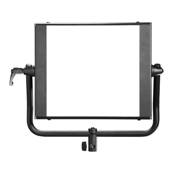
Summary of Contents for Velvet Light Series
- Page 1 Light 1 (IP54/Studio) Light 2 (IP54/Studio) Light 2X2 (Studio) Light 4 (IP54/Studio) Last updated on May 2022 User manual...
-
Page 2: Velvet Light
velvetlight.tv... - Page 3 For your own safety, please read and follow all safety instructions and precautions warnings. Exemption VELVET (THELIGHT Luminary) does not assume any responsibility for lighting from liability failures caused by malfunction of this product. The manufacturer disclaims liability for any damage to persons or property caused by inappropriate operation, damage of this kind lies in the responsibility of the operator.
- Page 4 LED panel side covers or front plastic diffuser. No user-serviceable parts inside. Maintenance and repair work to be carried out only by VELVET Service Centre. Do not cover the aluminium lamp head heat sink while using it. Proper ventilation must be provided.
-
Page 5: Table Of Contents
Power supply Beam Control Transport Rigging Cables Remote Control Placing into operation VELVET Light 1 & 2 Yoke to LED Panel assembling VELVET Light 2X2 Yoke to LED Panel assembling Pole Operated Yoke to LED Pannel assembling Mounting Options Security cables... - Page 6 Accessories installation Snapgrid installation Snapbag installation Diagrams VELVET Light 1 VELVET Light 2 VELVET Light 2x2 VELVET Light 4 Digital adjustments Color Dimming Master & slave DMX RDM controls Adressing channels Chromacity coordinates diagram Regulations Warranty Qr links...
-
Page 7: Main Features
(CCT) of the light emitted by VELVET and other LED light fixtures. The eventual diversions to green display as CC05M or CC10M in hand- held color meters are due to these unaccuracy on reading of the light emitted by LED and must not be considered. - Page 8 (NIST) of the United States and of the Physikalisch-Technische Bundesanstalt (PTB) of Germany. In order that the advanced VELVET luminaries could be used together with other light sources, VELVET has accurately calibrated both the CCT and the chromatic coordinates to match them with traditional light...
-
Page 9: Light Series Range Models
B. Light series families Light series range models IP54 Weatherproof IP51 Dustproof VL1IP54 VL1ST VELVET Light 1 weatherproof LED panel VELVET Light 1 Studio LED panel VL2IP54 VL2ST VELVET Light 2 weatherproof LED panel VELVET Light 2 Studio LED panel... -
Page 10: Velvet Light 1 Ip54 Weatherproof
IP54 Studio C. IP54 Weatherproof range models IP54 weatherproof range models VELVET Light 1 IP54 (Ref: VL1IP54) PARTS XLR-3 DC IN Power switch Adjustment buttons 3200K/ 5600K Quick access button Mode selection button (Dimmer/ Colour Temp) Digital display XLR-5 DMX In&Out... - Page 11 COOLING No-noise, fan-free passive cooling PROTECTION IP54 rainproof, indoor or outdoor use VELVET LED TECHNOLOGY Selected BIN LED + optic diffuser + CPU software control RIGGING OPTIONS Aluminum yoke with 16 female combined with 28 pin, quick link swivel ball head, pole operated yoke, multipanels yokes...
-
Page 12: Velvet Light 2 Ip54 Weatherproof
IP54 Studio C. IP54 Weatherproof range models VELVET Light 2 IP54 (Ref: VL2IP54) PARTS XLR-3 DC IN Power switch Adjustment buttons 3200K/ 5600K Quick access button Mode selection button (Dimmer/ Colour Temp) Digital display XLR-5 DMX In&Out... - Page 13 COOLING No-noise, fan-free passive cooling PROTECTION IP54 rainproof, indoor or outdoor use VELVET LED TECHNOLOGY Selected BIN LED + optic diffuser + CPU software control RIGGING OPTIONS Aluminum yoke with 16 female combined with 28 pin, quick link swivel ball head, pole operated yoke, multipanels yokes...
-
Page 14: Velvet Light 4 Ip54 Weatherproof
IP54 Studio C. IP54 Weatherproof range models VELVET Light 4 IP54 (Ref: VL4IP54) PARTS XLR-3 DC IN Power switch Adjustment buttons 3200K/ 5600K Quick access button Mode selection button (Dimmer/ Colour Temp) Digital display XLR-5 DMX IN... - Page 15 COOLING No-noise, fan-free passive cooling PROTECTION IP54 rainproof, indoor or outdoor use VELVET LED TECHNOLOGY Selected BIN LED + optic diffuser + CPU software control RIGGING OPTIONS Aluminum yoke with 16 female combined with 28 pin, quick link swivel ball head, pole operated yoke, multipanels yokes...
-
Page 16: Power Options
IP54 Studio C. IP54 Weatherproof range models POWER OPTIONS AC POWER 90 to 264 VAC STEP 1 Insert the power supply plate by sliding it into the slot located at the back of the panel. Insert and extract the plate from the right hand of the panel where the digital display is located. - Page 17 Connect any battery from 12 to 35 VDC to the XLR3 connector located at the back of the panel When powering VELVET from an external battery through the XLR3 connector check the proper polarity as shown in the picture at the side of the panel.
-
Page 18: Ip54 Weatherproof Models Accessories
Studio D. IP54 Weatherproof models accessories Weatherproof models accessories POWER SUPPLY VL-PSU120W 100W AC power supply + mount for VELVET Light 1 VL-PSU180W 180W AC power supply + mount for VELVET Light 2 VLIP54-PSU120W 120W weatherproof AC power supply + mount for... -
Page 19: Beam Control
IP54 Studio D. IP54 Weatherproof models accessories BEAM CONTROL VL1-RB Barndoors for VELVET Light 1 VL2-RB Barn doors for VELVET Light 2 VL4-RB Barn doors for VELVET Light 4 VL1-SG DopChoice 40º Foldable Snapgrid for VELVET Light 1 VL2-SG DopChoice 40º Foldable... -
Page 20: Transport
VELVET Light 2 Snapbag VL4-SGXSB DopChoice 40º Snapgrid for VELVET 4 Light Snapbag TRANSPORT VL1-BAG Soft bag for 1x VELVET Light 1 VL1-DBAG Soft bag for 2x VELVET Light 1 VL2-BAG Soft bag for 1x VELVET Light 2 VL1-CASE Flight case for VELVET Light 1... -
Page 21: Rigging
Center ball head for VELVET Light 2 VL4IP-PSUQLSSJ Center mount + AC PSU with cables for VELVET Light 2 VL4-Y Yoke kit for VELVET Light 4 CABLES CAB-XLR3DCC4.5M DC extension cable 4,5 meters / 15 feet XLR3 DMX-DMX2M DMX daisy-chain cable 2m / 6.5 feet... -
Page 22: Remote Control
IP54 Studio D. IP54 Weatherproof models accessories THE-DMXINOUT DMX aerial splitter in out REMOTE CONTROL VL-RC VELVET DMX remote control... -
Page 23: Velvet Light 1 Studio
IP54 Studio E. Studio range models IP51 Dustproof range models VELVET Light 1 Studio (Ref: VL1ST) PARTS XLR-3 DC IN Power switch XLR DMX-5 OUT Adjustment buttons 3200K/ 5600K Quick access button Mode selection button (Dimmer/ Colour Temp) Digital display... - Page 24 COOLING No-noise, fan-free passive cooling PROTECTION IP51 dustproof, indoor or outdoor protected use VELVET LED CYC TECHNOLOGY Selected BIN LED + optic diffuser + CPU software control RIGGING OPTIONS Aluminum yoke with 16 female combined with 28 pin, quick link swivel ball head, pole operated yoke, multipanels yokes...
-
Page 25: Velvet Light 2 Studio
IP54 Studio E. Studio range models VELVET Light 2 Studio (Ref: VL2ST) PARTS XLR-3 DC IN Power switch Adjustment buttons 3200K/ 5600K Quick access button Mode selection button (Dimmer/ Colour Temp) XLR DMX-5 OUT Digital display XLR-5 DMX IN... - Page 26 COOLING No-noise, fan-free passive cooling PROTECTION IP51 dustproof, indoor or outdoor protected use VELVET LED TECHNOLOGY Selected BIN LED + optic diffuser + CPU software control RIGGING OPTIONS Aluminum yoke with 16 female combined with 28 pin, quick link swivel ball head, pole operated yoke, multipanels yokes...
-
Page 27: Velvet Light 2X2 Studio
IP54 Studio E. Studio range models VELVET Light 2x2 Studio (Ref: VL2x2ST) PARTS Power switch XLR-3 DC IN Adjustment buttonsXLR-5 DMX OUT 3200K/ 5600K Quick access button Mode selection button (Dimmer/ Colour Temp) XLR-5 DMX Out Digital display XLR-5 DMX In... - Page 28 COOLING No-noise, fan-free passive cooling PROTECTION IP51 dustproof, indoor or outdoor protected use VELVET LED TECHNOLOGY Selected BIN LED + optic diffuser + CPU software control RIGGING OPTIONS Aluminum yoke with 28mm junior pin, multiple ¼-20” rigging points, multipanels yokes, pole operated yoke...
-
Page 29: Velvet Light 4 Studio
IP54 Studio E. Studio range models VELVET Light 4 Studio (Ref: VL4IP51) PARTS XLR-3 DC IN Power switch Adjustment buttons 3200K/ 5600K Quick access button Mode selection button (Dimmer/ Colour Temp) XLR DMX-5 IN Digital display XLR-5 DMX Out... - Page 30 COOLING No-noise, fan-free passive cooling PROTECTION IP51 dustproof, indoor or outdoor protected use VELVET LED TECHNOLOGY Selected BIN LED + optic diffuser + CPU software control RIGGING OPTIONS Aluminum yoke with 16 female combined with 28 pin, quick link swivel ball head, pole operated yoke, multipanels yokes QUICK MOUNTING AC power supply, foldable Snapgrid, 40º...
-
Page 31: Power Options
IP54 Studio E. Studio range models POWER OPTIONS AC POWER 90 to 264 VAC STEP 1 Insert the power supply plate by sliding it into the slot located at the back of the panel. Insert and extract the plate from the right hand of the panel where the digital display is located. -
Page 32: Studio Models Accessories
VELVET Light 1 Studio VL2ST-PSU 150W AC power supply +mount for VELVET 2 Studio VL2x2ST-PSU 300W AC power supply +mount plate for VELVET Light 2x2 Studio VL4ST-PSU 300W AC power supply +mount plate for VELVET Light 4 Studio BEAM CONTROL VL1-RB... - Page 33 IP54 Studio F. Studio models accessories VL2-SG20 DopChoice 20º Foldable Snapgrid for VELVET Light 2 VL2-SG60 DopChoice 60º Foldable Snapgrid for VELVET Light 2 VL2x2-SG20 DopChoice 20º Foldable Snapgrid for VELVET Light VL1-SB DopChoice SnapBag softbox for VELVET Light 1...
- Page 34 IP54 Studio F. Studio models accessories VL2X2-SPACEKIT Spacelight Hilite Kit + mount frame for VELVET Light 2x2 VL2x2-H Hanger mount for VELVET Light 2X2 VL2x2-SLOTKIT Slots kit for VELVET Light 2X2 2X2-RABBITSQ DopChoice Rabbit Ears frame for VELVET Light 2X2...
- Page 35 OCTA 5 foldable Snapbag 1,5m diameter for Rabbit Ears mount for VELVET Light 2X2 OCTA5-SG DopChoice 40º Snapgrid for Octa 5 for VELVET Light 2X2 OCTA-SBR07 OCTA 7 foldable Snapbag 2,1m diameter for Rabbit Ears mount for VELVET Light 2X2 OCTA7-SG DopChoice 40º...
-
Page 36: Transport
F. Studio models accessories TRANSPORT VL1-BAG Soft bag for 1x for VELVET Light 1 VL1-DBAG Soft bag for 2x VELVET Light 1 VL2-BAG Soft bag for 1x VELVET Light 2 VL1-CASE Flight case for VELVET Light 1 VL2-CASE Flight case for VELVET Light 2... -
Page 37: Cables
VL2X2-YPO Pole Operated yoke for VELVET Light 2X2 VL4-YPO Pole operated yoke kit for VELVET Light 4 VL2X2-YD Yoke disc Kit for VELVET Light CABLES CAB-XLR3DCC4.5M DC extension cable 4,5 meters / 15 feet XLR3 DMX-DMX2M DMX daisy-chain cable 2m / 6.5 feet... -
Page 38: Placing Into Operation
IP54 Studio G. Placing into operation Placing into operation VELVET LIGHT 1 & 2 YOKE TO LED PANNEL ASSEMBLING VL1-YT VELVET Light 1 & 2 yoke kit VL2-YT Spigots assembling pieces a. EV-EURO28-T Kit Euro 28mm junior pin for tubular yoke b. - Page 39 (*) Generally, spigots and yokes are assembled together, but depending on the size of the assembling box, the spigot may have to be assembled separately by the customer. Spigot mounting Ref: Ref: THE-2816CTUBE EV-EURO28-T STEP 2 Align the adjustable yoke with the VELVET Light panel as shown in the picture. Alignment...
- Page 40 IP54 Studio G. Placing into operation Assemble the yoke to the LED panel by using the mounting Kit of bolts STEP 3 (e), washers (g, h, i) and adjustable handle (f). First mount the handles Assembling with the metric M8 metal washer then insert the thick rubber washers steps between the yoke and the LED panel.
-
Page 41: Velvet Light 2X2 Yoke To Led Panel Assembling
IP54 Studio G. Placing into operation VELVET LIGHT 2X2 YOKE TO LED PANNEL ASSEMBLING VL2X2-YD Yoke disc kit for VELVET Light 2X2 a. TOR-D711M8 Thrust bearing M8 b. TOR-D6796M8 Conical spring washer M8 c. THE-UFIJACION U-Clamp for 2x2 yoke adjustable handle d. - Page 42 IP54 Studio G. Placing into operation Steps scheme STEP 1 Place the nylon cap and assemble this side of the yoke using the socket button head cap screw (h), the conical spring washer (b), the thrust bearing M8 and the yoke bushing (l). Place the ferodo washer between te yoke and the panel.
- Page 43 IP54 Studio G. Placing into operation STEP 2 Place the remaining nylon cap and use the socket buton cap screw again as an axis for the conical spring washer (b), the thrust bearing and the yoke bushing (i). Use the bottom hole to fix the wide wing washer M8 and the U-Clamp piece with the adjustable...
-
Page 44: Pole Operated Yoke To Led Pannel Assembling
IP54 Studio G. Placing into operation POLE OPERATED YOKE TO LED PANNEL ASSEMBLING VL1-YPO Pole operated yoke for VELVET VL2-YPO Light series and VELVET Power VL2X2-YPO series VL4-YPO STEP 1 Remove the ferodo washer fixed with two Philips countersunk head... - Page 45 IP54 Studio G. Placing into operation Display the panel over a table with the back facing to you and the STEP 3 display and tactile buttons to the right. Mount the Pole Operated yoke with the tilt gear box facing to the right. Insert the hexagon socket head cap screw M8x80 with its washer through the PO yoke gear box...
-
Page 46: Mounting Options
The LED panel is provided with several holes specially design to insert one o more snaps and their safety cable. When a VELVET panel and any other component is mounted in a hanging position it must be secured with a safety cable rated at a minimum of ten times the weight of the light fixture including its accessories. -
Page 47: Accessories Installation
VL4-SG VL2x2-SG20 STEP 1 Position the VELVET panel with the light pointing up. Unfold the snapgrid, place it over the VELVET diffuser and flip the elastics over the panel corners to secure it. The side covers prevent emitting of spill light. -
Page 48: Snapbag Installation
Studio H. Accessories installation SNAPBAG INSTALLATION VL1-SB DopChoice SnapBag softbox for VL2-SB VELVET Light series and VELVET VL2X2-SB Power series VL4-SB STEP 1 Open the Snapgrid and secure it over the EVO PANEL by hooking the rear velcro strips (a). - Page 49 IP54 Studio H. Accessories installation At the end of process, secure again all velcros and tensors.Check the STEP 3 front corners and finish the assembly using the central maintensioners so that the assembly looks equal, centered and firm. STEP 4 Hook in the intermediate diffuser fabric using the white velcro strips on the corners of the snap bag.
- Page 50 IP54 Studio I. Diagrams Diagrams VELVET Light 1+MO Yoke 485 mm 370 mm 295 mm 308 mm THE-2816CTUBEK EV-EURO28-T VELVET Light 1+PO Yoke 435 mm...
- Page 51 IP54 Studio I. Diagrams VELVET Light 2+MO Yoke 815 mm 670 mm 592 mm mm 515 THE-2816CTUBEK EV-EURO28-T VELVET Light 2+PO Yoke 880 mm...
-
Page 52: Velvet Light 2X2
IP54 Studio I. Diagrams VELVET Light 2X2+MO Yoke 690 mm 670 mm 592 mm VELVET Light 2X2+PO Yoke 880 mm... - Page 53 IP54 Studio I. Diagrams VELVET Light 4+MO Yoke 1365 mm 1250 mm 1174 mm VELVET Light 4+PO Yoke 1365 mm...
-
Page 54: Digital Adjustments
The digital control enables to adjust the following light parameters through its programmed CPU: •Calibrated color temperature variation •Stable color dimming Color VELVET Light series includes a dedicated button to immediately set temperature 3200K or 5600K. variation Color temperature can also be increased or reduced through the buttons located at the digital control panel. -
Page 55: Dimming
Light product together and operate them all without a controller. The first VELVET fixture will be the Master acting as the controller and all the others will react and copy the color temperature and dimmer values. Use DMX XLR-5 in&out splitter cables (ref. THE-VL-DMXinout) to daisy chain several VELVET Light panels. -
Page 56: Dmx Rdm Controls
Every time you switch off the power button the VELVET panels are automatically set to SLAVE mode. Only the first VELVET panel on the chain can be the Master. Every other VELVET panels must be set on standard Slave mode and address at channel 001. -
Page 57: Adressing Channels
• After the DMX address is entered the fixture will automatically assign the following channel • If you wish to control several VELVET fixtures at the same values you will have to set them to the same address • If you wish to control several VELVET fixtures independently you will have to offset their address by 2 channels. -
Page 58: Chromacity Coordinates Diagram
D illuminants. The diagram evidence the light emanated by VELVET luminary at every color temperature entirely matches with the described locus reference so that the color of the light produced is essentially the same as incandescent and daylight. - Page 59 30932004, with its accessory TOP-100 has an imprecision over the spectral radiometric results delivered lower than 1%. Specifications subject to change without notice. VELVET technology is protected under Spanish license laws with international patents pending. THELIGHT luminary for cine and tv, S.L...
-
Page 60: Regulations
VELVET Cyc3, Cyc4, Cyc5, Cyc6 VELVET Mini 1, Mini 2, Mini 3 VELVET Mini Power 1, Mini Power 2 VELVET Light 1, Light 2, Start 2, Light 2x2, Light 4 VELVET Power 1, Power 2, Power 2x2 VELVET Sword 2, Sword 4. - Page 61 IP54 Studio L. Regulations DIRECTIVE 2011/65/EU of the European Parliament and of the Council of 8 June 2011on the restriction of the use of certain hazardous substances in electrical and electronic equipment. In compliance with the harmonized standards: IEC 60598-1:2014 Luminaires - Part 1: General requirements and tests. IEC 60598-1-17:2017 Luminaires - Part 2-17: Particular requirements - Luminaires for stage lighting, television and film studios (outdoor and indoor).
-
Page 62: Warranty
M. Warranty Warranty General warranty VELVET LED light equipments are guaranteed to be free from defects in workmanship and parts in a warranty period of two (2) years from the date of purchase. Defects that occur within this warranty period, under normal use and care will be repaired or replaced at VELVET discretion, solely at our option with no charge for parts or labour. - Page 63 The total or partial reproduction of this guide is prohibited without the express written permission of VELVET. VELVET technology is protected under Spanish license laws with international patents pending. Information and specifications in this document are subject to change without notice.
-
Page 64: Qr Links
IP54 Studio N. QR links QR Links VELVET Light series website VELVET Light series suport documents... - Page 65 velvetlight.tv...
- Page 68 Design, Engineering & Production center Carrer de la Cerdanya. 11A 08192 — St. Quirze del Vallès Barcelona (Spain) +34 937 073 011 info@velvetlight.com VELVET USA Office 7411 Laurel Canyon, unit 3 North Hollywood, CA 91605 +1 (818) 358 2888 usa@velvetlight.tv velvetlight.tv...
Need help?
Do you have a question about the Light Series and is the answer not in the manual?
Questions and answers