Advertisement
Quick Links
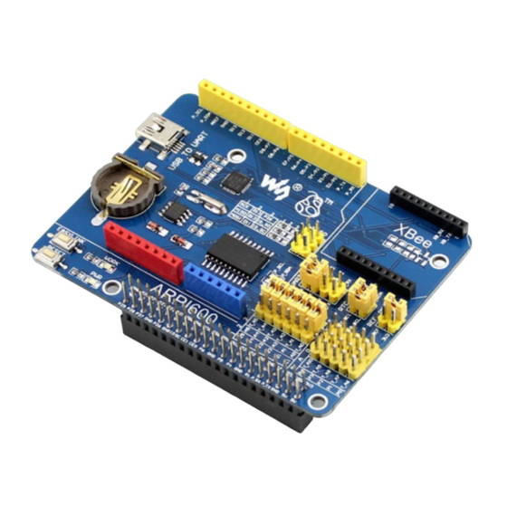
ARPI600 User Manual
Overview
Arduino is a massive ecosystem, if there's a way for the Raspberry Pi GPIO interface to
adapt to Arduino pinouts, it is possible to use the Pi together with vast Arduino shields
and hardware/software resources. The ARPI600 is just intended for this.
What's more, the ARPI600 also support XBee modules, make it easy to add wireless
feature to your great project.
Features
Compatible with Arduino UNO, Leonardo, easy to connect with various Arduino
shields
XBee connector for connecting various XBee modules
Sensor interface for connecting various sensors
Onboard USB TO UART for serial port debugging, also can be configured as XBee
USB adapter
Onboard ADC, 10 bit, 38KSPS, 11 channels (6 channels for Arduino interface, 5
channels for sensors)
Onboard RTC
w w w . e k t
. c o m
2
ARPI600
User Manual
Electronics
Katrangi
Trading
Advertisement

Related Manuals for EKT ARPI600

Summary of Contents for EKT ARPI600
- Page 1 Arduino pinouts, it is possible to use the Pi together with vast Arduino shields and hardware/software resources. The ARPI600 is just intended for this. What's more, the ARPI600 also support XBee modules, make it easy to add wireless feature to your great project.
- Page 2 ARPI600 User Manual What's on the ARPI600 Figure 1: Onboard device 1. Arduino connector : for connecting Arduino shields 2. ICSP interface : Arduino ICSP 3. XBee connector : for connecting XBee communication modules 4. Sensor interface : for connecting sensors 5.
- Page 3 ARPI600 User Manual 17. RTC jumper 18. UART jumper when connecting P_RX and CP_TX, P_TX and CP_RX respectively, USB TO UART is connected to Raspberry Pi serial port when connecting XB_RX and CP_TX, XB_TX and CP_RX respectively, USB TO UART is connected to XBee serial port...
- Page 4 After connecting ARPI600 to Raspberry Pi board, you should power up the Raspberry Pi board and then connect ARPI600 to the USB port on your PC. It is not recommended to connect ARPI600 to the USB port on PC before powering up Raspberry Pi board or for...
- Page 5 ARPI600 User Manual Figure 3: PuTTY settings Then, you will see a window popped up as Figure 4 shows (If there is nothing shown in the window, please press the key Return Carriage, then you can see the information displayed as Figure 4 shows).
- Page 6 ARPI600 User Manual How to control peripherals by Raspberry Pi 2.1 System serial port configuration Enter the terminal of Raspberry Pi, and input: sudo nano /boot/cmdline.txt Then, you should modify the following lines: wc_otg.lpm_enable=0 console=ttyAMA0,115200 kgdboc=ttyAMA0,115200 console=tty1 root=/dev/mmcblk0p2 rootfstype=ext4 elevator=deadline rootwait into: dwc_otg.lpm_enable=0 console=tty1 root=/dev/mmcblk0p2 rootfstype=ext4...
- Page 7 Now, you can check whether the installation is successful. 2.3 Serial data display Set the jumpers on the ARPI600: connect P_RX to P_TX, and CP_TX to CP_RX. And connect the ARPI600 to the USB port on your PC. Start the PuTTY serial debugging software to configure following parameters: Serial line: it is used to select corresponding serial port.
- Page 8 3.3 Testing the connection between PC and XBee Connect XBee-A to ARPI600-A, and XBee-B to ARPI600-B, respectively. Set the jumpers on ARPI600 to start up the serial debugging function for the XBee, as Figure 7 shows. Connect XB_RX to CP_RX ...
- Page 9 ARPI600 User Manual Figure 8: Testing the connection between the board and the XBee For a successful connection, you can see the dialog box as Figure 9 shows. Figure 9: Successful connection 3.4 Configuring XBee-A module Select the option Modem Configuration, and click the button Read to read out the current parameters of XBee.
- Page 10 ARPI600 User Manual Figure 10: Reading out current parameters Select the option ZIBGEE ROUTER/END DEVICE AT under the pull-down menu Function Set: Figure 11: Selecting the option ZIBGEE ROUTER/END DEVICE AT under Function Set Set the read Networking parameters: ID: 234 ...
- Page 11 ARPI600 User Manual 3.5 Configuring XBee-B module Configure XBee-B module according to the processes described in the Section 3.1 and the Section 0. However, there is something different. In configuring XBee-B, you should select the option ZIBGEE COORDINATOR AT under the pull-down menu...
-
Page 12: Configuring The Module
Raspberry Pi-A is used for transmitting data and Raspberry Pi-B is used for receiving data. Connect Raspberry Pi-A to the serial port of XBee-A and Raspberry Pi-B toXBee-B, respectively. And then, set the jumpers on ARPI600, as Figure 14 shows. Connect XB_RX to P_TX ... -
Page 13: Rtc Clock
Raspberry Pi-B Figure 16: Message received by 5 RTC clock Set the jumpers on RTC JMP of the ARPI600. Open the LXTerminal on the desktop of Raspbian, and input the code: i2cdetect -y 1 Then, you will see the device address of PCF8563 connected to Raspberry Pi. Here, the device address of PCF8563 is 51, which means the PCF8563 is identified by Raspberry Pi. - Page 14 -r (Synchronize the time of Raspbian to PCF8563) hwclock -s (Synchronize the time of Raspbian with hardware RCT) 6 AD conversion (ARPI600 on-board chip TLC1543) 6.1 Configuring Pin A0 to Pin AD Please make sure you have installed relative libraries (refer to the Section 2.2: Installing relative libraries).
-
Page 15: Interface Description
ARPI600 User Manual conversion value is come from Pin AD0 on TLC1543 (Pin T_A0 on ARPI600). Connect the jumpers T_A0 to A0, then the Pin A0 on Arduino interface can sever as an AD conversion pin, as shows. Figure 19: connecting Pin T_A0 to Pin A0 6.2 Configuring as other AD pins... - Page 16 Notices: Users can modify the settings of these jumpers as required. In this operation, welding is required. Any changes under no guidance from Waveshare will be considered as a waiver of warranty. The pins A0-A5 of ARPI600 can also be configured as IO pins or ADC pins. Katrangi Electronics Trading w w w .
- Page 17 Figure 22: Setting the pins A4 and A5 as I2C control pins ARPI600 provides sensor interfaces 4P. Figure 23 shows the jumper settings for sensor interface 4P. Figure 23: Sensor interface 4P...
Need help?
Do you have a question about the ARPI600 and is the answer not in the manual?
Questions and answers