
Related Manuals for North America Traffic RCF 2.4


Summary of Contents for North America Traffic RCF 2.4
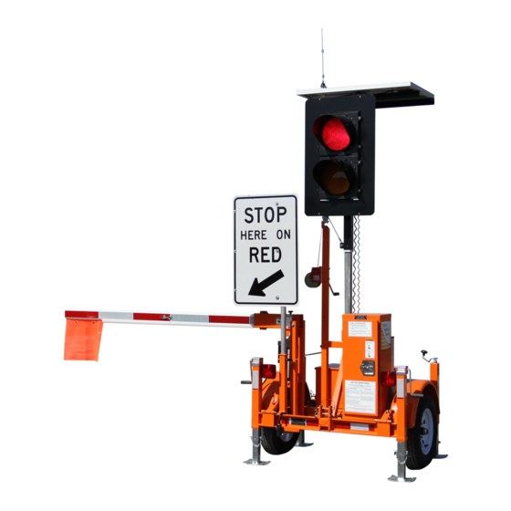
- Page 1 RCF 2.4 Automated Flagger Assistance Device Manual THE LEADER IN TRAFFIC CONTROL SYSTEMS REV 08 02.10.22...
- Page 2 The North America Traffi c, Inc. Model RCF 2.4 Automated Flagger Assistance Device (AFAD) is used as an alternative to traditional fl agging operations. The RCF 2.4 AFAD is designed to take Traffi c Control Persons out of harm’s way while continuing to maintain complete control over the construction/work zone by use of a wireless Hand Held Radio Remote Control.
- Page 3 7.1 L 1.1 T 1.2 T 9.1 S 1.3 S 9.2 O 1.4 E 10 D 1.5 B 10.1 F 1.6 O 10.2 S 10.3 S 11 O 3.1 T 11.1 R (RMS) 3.2 T 11.2 I 3.3 C 12 C 12.1 R 4.1 T 12.2 H...
- Page 4 ECTION All personnel operating the North America Traffi c RCF 2.4 must be fully trained. Prior to transporting the RCF 2.4 (either individually and/or in tandem) complete the following checklist to ensure safety while in tow: • All lock down points are secure including: Tongue locking pin ◦...
- Page 5 ECTION Gas Explosion or Fire Batteries release an explosive hydrogen gas while being charged. Keep cigarettes, sparks, fl ames, and any other ignition sources away at all times. Acid Burns Battery acid can cause burns if it comes in contact with exposed skin and can cause blindness when in contact with your eye(s).
- Page 6 ECTION AFAD – defi ned as ‘Automated Flagger Assistance MUTCD – the Manual on Uniform Traffi c Control Device’. An AFAD enables a fl agger(s) to be po- Devices. Contains regulatory information on the sitioned away from the lane of traffi c and is used use of AFAD’s in temporary traffi...
- Page 7 ECTION 1. Solar Panel • The solar panel supplied with every RCF 2.4 provides 100 Watts of power and is housed in an anodized aluminum frame. • The solar energy is sent to the solar charge controller which then transfers the power to the battery bank.
- Page 8 SYSTEM INFORMATION S ECTION 6. Trailer Section Components • The Trailer Section for the RCF 2.4 is approved for use on highways including the following features: ◦ Torsion axle, rated at 1100 lbs ◦ ST175/80R13 tires ◦ Removable tongue with one (1) locking pin ◦...
- Page 9 ECTION 1. STOP HERE ON RED Sign Holder: the sign is fi xed in this position and rotates 90° for deployment. 2. Gate Arm Holder: gate arm is stored in this holder for transport. It is a gravity fi t; no locking pin is required.
- Page 10 ECTION 1. Controller – controls all functions of the RCF 2.4. RCF 2.4 RCF2.4XXX 2. Wiring Conduit – protected channel through which wires are routed. 3. Terminal Block – all electrical inputs and outputs are applied here. 4. Main Power On/Off Switch 5.
- Page 11 ECTION f. Repeat for the other top and side wind jacks on the rear trailer. Ensure all jacks are dropped before separating the two trailers. 2. Proceed to the connection point between the two trailers and disconnect the running light cable.
- Page 12 ECTION 1. Before disconnecting the unit from the towing CAUTION vehicle, drop the two front jacks (top wind). Also lower the two rear jacks (side wind) about three Ensure all jacks are deployed and the unit is quarters of the way down. Refer to steps 1a. level before raising the light post.
- Page 13 ECTION 4. Reference the two arrow decals (one located on 9. Align the holes of the gate arm and sleeve and the light post, the other on the winch mast) for insert the hitch pin to secure in place. proper deployment height. When the two arrows are aligned, the signal housing will be deployed to the MUTCD recommended height of 7 feet (as measured to the underside of the...
- Page 14 ECTION 5. Proceed to the front of the trailer and locate the Improper hitch height can result in diffi culty locking the trailers, and cause trailer instability hand winch. during transport. 6. Firmly grasp the handle of the winch and turn it counterclockwise to lower the light post.
- Page 15 ECTION 4. Slowly reverse the front unit until the coupler is above the cradle. b. While holding the base of the jack, remove the locking pin. 5. Lower the two front jacks on the rear unit until the coupling bar rests in the cradle. 6.
- Page 16 ECTION 4. Proceed to the rear of the lead trailer and remove the two 1/2” hitch pins from the coupling cradle. 5. Insert the hitch adapter into the coupling cradle Note: The tandem towing confi guration requires and secure with the two 1/2” hitch pins that additional hardware.
- Page 17 ECTION Gen 3 Controller 1. Soft Buttons – these 10 buttons have no specifi c assigned values. They will have a different value on each screen. 2. BACK Button – returns to the previous menu screen. 3. L.E.D. Status Lights: - indicates whether there is a ALERT fault or error message.
- Page 18 ECTION The systems tray will display pertinent information that is always visible. DEFAULT ALL RED FEB/01/17 09:53AM PRESS START TO RESUME PROGRAM: MODEL V## BATTERY: 24.0 VOLTS HOME UNIT: PRIMARY RADIO CHANNEL: 03 RADIO SIGNAL: 1. System Feedback – this will display any instructions, faults or error messages that occur. 2.
- Page 19 ECTION FAULT LOGS MENU and CLEAR the FAULT. Communica on will be restored. Once unlocked, the only way to lock the software again is to go back to the OPTIONS menu and select the corresponding soft button. DEFAULT FLASH RED FEB/01/17 09:53AM PRESS START TO RESUME PROGRAM: AFAD V##...
-
Page 20: Table Of Contents
ECTION DEFAULT ALL RED FEB/01/17 09:53AM DEFAULT ALL RED FEB/01/17 09:53AM PRESS START TO RESUME PRESS START TO RESUME PROGRAM: AFAD V## PROGRAM: AFAD V## BATTERY: 24.0 VOLTS HOME BATTERY: 24.0 VOLTS HOME UNIT: PRIMARY RADIO CHANNEL: 03 RADIO SIGNAL: UNIT: SECONDARY 1 RADIO CHANNEL: 03 RADIO SIGNAL:... - Page 21 ECTION (0-10sec) that will occur between when the RED Single Unit - Pilot - A single unit can be indication is lit, and when the gate arm begins controlled. A pilot car equipped with a radio to lower. remote can control the work zone without the need for a fl...
-
Page 22: Default All Red Press Start To Resume
ECTION Note: When operating in Gen 1 AFAD using the up and down arrow buttons to select compatibility mode, the Gen 3 system must the value and the right and left arrow buttons to ALWAYS be the PRIMARY unit. The Gen 1 units toggle horizontally. -
Page 23: Unit Id
ECTION When setting up a work zone, one unit must be set as the Primary Unit. If more than one unit is needed, the other unit will be setup as Secondary 1. The Secondary Units should be powered on fi rst. Edit the OPTIONS menu settings as shown below on the Primary and Secondary controllers;... - Page 24 ECTION i. Select START PROGRAM (program can be started from the CHANGE TIMING screen or the HOME screen). Layout Units Required Control Mode One-Way Zone - Single Unit Primary Manual One-Way Zone - Two Unit Primary, Secondary 1 Manual/Pilot Car Two-Way Zone (Manual Mode) Primary, Secondary 1 Manual Disclaimer...
- Page 25 ECTION...
- Page 26 ECTION...
- Page 27 LED light near the button will light up confi rming a valid command has been received by the RCF 2.4. You must press and hold the button for 3 seconds until the LED illuminates. Radio Remote Push Buttons Functions: (Manual Mode) •...
- Page 28 ECTION Setting the Radio Channel: Note: Setting the radio channel of the remote can be done at either the Primary or Secondary unit. 1. From the HOME screen, select SYNC RADIO REMOTE. 2. Pressing and holding the black and red buttons at the same time after selecting SYNC RADIO REMOTE on the controller will confi...
-
Page 29: Radio Channel
ECTION The Gen 3 CU has the capability of interfacing and operating with North America Traffi c’s previous generation of AFAD signal controller, known as Gen 1. Gen 1 - Portable Traffic Signal Controller STOP FLASH MENU DISTANCE GREEN MASTER (SEC) (SEC) (VOLTS) - Page 30 Gen 3 primary unit). The Gen 3 AFAD RCF 2.4 will operate with Gen 1 AFAD units using program version 62-7. Due to the software structure of the Gen 1 system, unit ID’s are not alike (or interchangeable) between the Gen 3 and Gen 1.
-
Page 31: Radio Channel
ECTION 10.1 The FAULT LOGS records both systems faults, as well as operational data. 10,000 events are held in memory for viewing on-screen or by means of export to a spread sheet fi le format. Fault logs can be viewed at any unit within the network (PRIMARY or SECONDARY). Any fault event can be cleared from the PRIMARY unit (given the issue that caused the fault has been resolved), but only local fault events can be cleared at the SECONDARY unit at which the fault event took place. -
Page 32: Options
ECTION 5. Remove USB fl ash drive after the Export Status pop-up window disappears. Note: If a previous data log is present on the USB fl ash drive, it will be overwritten by the next log export. Save or copy the existing log fi le to a computer prior to accepting another log fi le export to prevent data loss. - Page 33 ECTION Phase Status (PHZ): CURRENT PHASE – displays which unit(s) is being served DEFAULT FLASH RED FEB/01/17 09:53AM PRESS START TO RESUME PROGRAM: MODEL V## by the current phase. BATTERY: 24.0 VOLTS HOME > PHZ STATUS UNIT: PRIMARY RADIO CHANNEL: 03 RADIO SIGNAL: TIME –...
- Page 34 - user can set up desired radius; if the AFAD is moved outside the desig- (Geo-Fencing) nated area, the user is no fi ed by text or email 11.2 The intrusion alarm system requires the following hardware additions on the base RCF 2.4: • siren amplifi er • siren speaker • intrusion infrared sensor...
- Page 35 ECTION Application The intrusion alarm (when enabled) will sound the siren if a vehicle passes through a red indication. This notifi es the workers on site of a vehicular intrusion, granting them time to exit the roadway. The intrusion alarm sensor becomes inactive when a “fl ash amber” phase is served. Once the unit transitions to an ALL STOP, the intrusion sensor becomes active.
- Page 36 ECTION 12.1 Best Practices: • Operate with strong radio signal strength. At least 50% strength consistently (see Systems Tray). • Operate within 1/2 mile (0.8 km) apart including line of site (if using the standard omni-directional antenna). Common Interference: • Anything that interrupts line of sight between the units. i.e. tractor trailers, bridges, heavy equipment, elevation changes.
- Page 37 13.1 The RCF 2.4 has one (1) 100 Watt solar panel. The solar panel is regulated with a 10 amp regulator. The solar panel provides only supplemental charge to the battery bank and does not allow for infi nite opera- tion.
- Page 38 Lead acid batteries are ‘non-memory’ and over-discharge will cause damage and premature battery failure. To avoid over-discharge, the RCF 2.4 notifi es the user of low battery voltage (23.6 Volts or less) by emitting a continual beep and displaying the message ‘CHARGE FOR 24 to 48 HOURS’ on the screen.
- Page 39 ECTION Generators can output high voltage spikes upon initial startup. To protect the battery charger from such voltage spikes, allow the generator to run for a few minutes after initial startup, then make the connection to the battery charger.
- Page 40 ECTION Please refer to website for latest maintenance forms. www.northamericatraffi c.com 14.1 Performing routine maintenance on your Automated Flagger Assistance Device is critical to ensuring safety while in tow, as well as the longevity of the trailer and its components. The items below are critical compo- nents that should be inspected on a monthly basis.
- Page 41 ECTION Inspection of Trailer Components: a. Check Tongue Hitch Coupler: Routinely check that the tongue hitch coupler is torqued to 45 ft/lbs. b. Check Hitch Coupler Components: Check the hitch coupler components to ensure the latch has full range of motion. Ensure the coupler locks on the ball without movement or play.
- Page 42 ECTION Message Descrip on Cause Solu on CHECK SETTINGS THEN PRESS Primary unit is ready to op- Machine(s) running properly Press “Start” bu on on START erate Primary when ready to start program CYCLE PAUSED While running automa c cycle User has paused the cycle Press the green bu on on (all red) with the hand held HHR when ready to start...
- Page 43 ECTION Message Descrip on Cause Solu on REPAIR COMMUNICATION Controller is not recognizing The J0 radio harness is discon- Reconnect the J0 radio har- RADIO MODEM a connec on to the radio nected. ness. modem. 35 feet antenna cable is Replace 35 feet Antenna cable malfunc oning and needs to be replaced.
-
Page 44: Secondary
ECTION Message Descrip on Cause Solu on SITE INTERFERENCE CHANGE Controller is recognizing units There is a local signal nearby Change the radio channel, or RADIO CHANNEL in the system that are causing opera ng on the same radio assign a CUSTOM PASSCODE radio interference. - Page 45 ECTION Message Descrip on Cause Solu on BATTERY LOW CHARGE FOR Ba ery bank voltage is read- Ba ery charge is below 23.6V, Plug internal charger into 48 HRS ing low machine will s ll operate 110V power source for min- imum 24hrs of con nuous charging MALFUNCTION RESPONSE...
- Page 46 1/2” x 6 1/2” Hitch Pin (Towing, Gate Arm) x5 300-0093 T-Handle Latch 500-0168 J1 Harness 400-0212 J2 Harness 400-0213 24V RCF 2.4 Actuator 500-1143 Abus Lock 500-0001 LED Running Light Kit 400-0272 Rb-78 24” x 36” Stop Here on Red Signal Sign (Canada) 500-1103 R10-6 24”...
- Page 47 ECTION Part Name Part Number Quick Release Locking Pin 3/8” x 5” (gate arm) 300-0092 Quick Release Locking Pin 1/2” x 2 1/2” (sign) 500-1138 Gate Arm Breakaway Rubber Clamping Bushings 500-1136...