
Related Manuals for North America Traffic RCF 2.4


Summary of Contents for North America Traffic RCF 2.4
- Page 1 RCF 2.4 Automated Flagger Assistance Device Manual THE LEADER IN TRAFFIC CONTROL SYSTEMS REV 01 08.29.19...
-
Page 2: Introduction
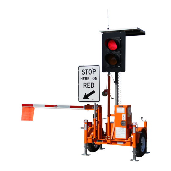
Hand Held Radio Remote Control. To ensure safe passage within the work zone, the RCF 2.4 AFAD comes equipped with user friendly programming options and conflict monitoring. The 4 inch gate arm and 12 inch LED signal lamps provide positive information to the public, designating when to “Stop”... -
Page 3: Table Of Contents
Contents Introduction 9 Compatibility Mode 1 Safety Overview 9.1 Setting Compatibility Mode on Gen 3 9.2 Operating With Gen 1 1.1 Training 10 Data Management 1.2 Towing 1.3 Signage and Work Zone 10.1 Fault/Data Logs 1.4 Electrical Hazards 10.2 System Status and Diagnostics 1.5 Battery Hazards 10.3 Software Import/Export 11 Optional Equipment... -
Page 4: Safety Overview
All personnel operating the North America Traffic RCF 2.4 must be fully trained. Towing Prior to transporting the RCF 2.4 (either individually and/or in tandem) complete the following checklist to ensure safety while in tow: • All lock down points are secure including: ◦... -
Page 5: Overhead Hazards
ection Gas Explosion or Fire Batteries release an explosive hydrogen gas while being charged. Keep cigarettes, sparks, flames, and any other ignition sources away at all times. Acid Burns Battery acid can cause burns if it comes in contact with exposed skin and can cause blindness when in contact with your eye(s). -
Page 6: Terms And Definitions
ection Terms and Definitions AFAD – defined as ‘Automated Flagger Assistance Radio Remote Control – sometimes referred to as Device’. An AFAD enables a flagger(s) to be po- a ‘Hand Held Remote’ or ‘HHR’. This device per- sitioned away from the lane of traffic and is used mits the user to manually operate the AFAD unit(s) to control vehicle movements through temporary wirelessly from a safe distance. -
Page 7: Component Breakout
Trailer Deployed 1. Solar Panel • The solar panel supplied with every RCF 2.4 provides 100 Watts of power and is housed in an anodized aluminum frame. • The solar energy is sent to the solar panel controller which then transfers the power to the battery bank. - Page 8 SYSTEM INFORMATION S ection 6. Trailer Section Components • The Trailer Section for the RCF 2.4 is approved for use on highways including the following features: ◦ Leaf spring axle, rated at 2200 lbs ◦ ST175/80R13 tires ◦ Removeable tongue with one (1) locking pin ◦...
-
Page 9: Trailer In Transport
ection Trailer in Transport 1. Auxiliary Holder: used for storage of the tongue or spare tire mount. Holds the STOP HERE ON RED sign when the unit is in operation. Note: spare tire mount and spare tire are optional extras. 2. -
Page 10: Cabinet Internals
Cabinet Internals 1. Controller – controls all functions of the RCF 2.4. 2. Wiring Conduit – protected channel through which wires are routed. 3. Terminal Block – all electrical inputs and outputs are applied here. 4. Main Power On/Off Switch 5. -
Page 11: Physical Setup/Takedown
ection f. Repeat for the other top wind and side wind Physical Setup/Takedown jacks on the rear trailer. Ensure all jacks are dropped before separating the two trailers. 2. Proceed to the connection point between the Trailer Separation two trailers and disconnect the running light coupling cable from both trailers. -
Page 12: Disconnect From Towing Vehicle
ection Disconnect from Towing Vehicle Deployment Onsite 1. Before disconnecting the unit from the towing CAUTION vehicle, drop the two front jacks (top wind). Also lower to two rear jacks (side wind) about three Ensure all jacks are deployed and the unit is quarters of the way down. -
Page 13: Takedown Onsite
ection 6. Insert the locking pin in the sign receiver tube Takedown Onsite to secure the sign in place. WARNING Ensure temporary traffic control is operating prior to stepping onto the roadway. Failure to do so may result in injury or death due to vehicular impact. -
Page 14: Connection To Towing Vehicle
ection 8. Firmly grasp the handle of the winch and turn it 7. Reverse the towing vehicle so the ball hitch is Note: counterclockwise to lower the light post. underneath the tongue coupler. there will be no clicking “noise” when cranking 8. - Page 15 ection remain deployed roughly three quarters of the way down. 2. Reverse the trailer connected to the towing vehicle just in front of the rear trailer to be connected. 3. Raise the rear unit using the front jacks (top wind) enough for the coupler on the rear unit to clear the ball hitch on the front unit.
-
Page 16: Controller Navigation
ection Controller Navigation Controller Hardware Gen 3 Controller 1. Soft Buttons – these 10 buttons have no specific assigned values. They will have a different value on each screen. 2. BACK Button – returns to the previous menu screen. 3. L.E.D. Status Lights: - indicates whether there is a ALERT fault or error message. -
Page 17: Controller Software
Once this is entered, a prompt will appear to enter a new passcode. If your custom passcode is ever forgotten, call North America Traffic: 1-877-352-4626. After a new passcode is set, in order to alter any settings, the software will need to be unlocked. This can be accomplished either by unlocking the software via the OPTIONS menu or by selecting any option to edit. -
Page 18: Internal Software Navigation
ection Once unlocked, the only way to lock the software again is to go back to the OPTIONS menu and select the corresponding soft button. DEFAULT FLASH RED FEB/01/17 09:53AM PRESS START TO RESUME PROGRAM: AFAD V## BATTERY: 24.0 VOLTS HOME >... -
Page 19: Menu Screens
ection Menu Screens DEFAULT ALL RED DEFAULT ALL RED FEB/01/17 09:53AM FEB/01/17 09:53AM PRESS START TO RESUME PRESS START TO RESUME PROGRAM: AFAD V## PROGRAM: AFAD V## BATTERY: 24.0 VOLTS HOME BATTERY: 24.0 VOLTS HOME UNIT: PRIMARY RADIO CHANNEL: 03 RADIO SIGNAL: UNIT: SECONDARY 1 RADIO CHANNEL: 03... - Page 20 ection lowering, the gate arm will stop and return to Lamp Outputs – additional lamps to notify the vertical position. workers of the signal lamp(s) status. Back Lamp – a 4” amber lamp used to notify DEFAULT FLASH RED FEB/01/17 09:53AM PRESS START TO RESUME PROGRAM: AFAD V## the workers within the work zone.
-
Page 21: Starting Operations
ection shall all be set as SECONDARY units. minutes, the screen will go black. Press any button to illuminate the screen. Factory Settings – gives you the option to enable or disable display dimming and set the Set Model – Manufacturer access only. Contact product model. -
Page 22: Setting Up A Work Zone
ection Setting Up a Work Zone When setting up a work zone, one unit must be set as the Primary Unit. If more than one unit is needed, the other unit will be setup as Secondary 1. The Secondary Units should be powered on first. Edit the OPTIONS menu settings as shown below on the Primary and Secondary controllers;... -
Page 23: Layouts
ection Layouts Layout Units Required Control Mode One-Way Zone - Single Unit Primary Manual One-Way Zone - Two Unit Primary, Secondary 1 Manual/Pilot Car Two-Way Zone (Manual Mode) Primary, Secondary 1 Manual Disclaimer Please consult the presiding traffic control manual to ensure proper work zone setup. The following illustrations are not drawn to scale and are meant to be used as a guide in determining the proper setup of the signals. - Page 24 ection...
- Page 25 ection...
-
Page 26: Radio Remote
LED light near the button will light up confirming a valid command has been received by the RCF 2.4. You must press and hold the button for 3 seconds until the LED illuminates. Radio Remote Push Buttons Functions: (Manual Mode) •... - Page 27 ection Setting the Radio Channel: Note: Setting the radio channel of the remote can be done at either the Primary or Secondary unit. 1. From the HOME screen, select SYNC RADIO REMOTE. 2. Pressing and holding the black and red buttons at the same time after selecting SYNC RADIO REMOTE on the controller will configure the controller radio channel to the radio remote.
-
Page 28: Compatibility Mode
Compatibility Mode The Gen 3 CU has the capability of interfacing and operating with North America Traffic’s previous generation of AFAD signal controller, known as Gen 1. Gen 1 - Portable Traffic Signal Controller STOP FLASH MENU DISTANCE GREEN... - Page 29 Gen 3 primary unit). Operating With Gen 1 The Gen 3 AFAD RCF 2.4 will operate with Gen 1 AFAD units using program version 62-7. Due to the software structure of the Gen 1 system, unit ID’s are not alike (or interchangeable) between the Gen 3 and Gen 1.
-
Page 30: Data Management
ection Data Management 10.1 Fault/Data Logs The FAULT LOGS records both systems faults, as well as operational data. 10,000 events are held in memory for viewing on-screen or by means of export to a spread sheet file format. Fault logs can be viewed at any unit within the network (PRIMARY or SECONDARY). Any fault event can be cleared from the PRIMARY unit (given the issue that caused the fault has been resolved), but only local fault events can be cleared at the SECONDARY unit at which the fault event took place. -
Page 31: System Status And Diagnostics
ection 5. Remove USB flash drive after the Export Status pop-up window disappears. Note: If a previous data log is present on the USB flash drive, it will be overwritten by the next log export. Save or copy the existing log file to a computer prior to accepting another log file export to prevent data loss. -
Page 32: Software Import/Export
ection Phase Status (PHZ): DEFAULT FLASH RED CURRENT PHASE – displays which unit(s) is being served FEB/01/17 09:53AM PRESS START TO RESUME PROGRAM: MODEL V## by the current phase. BATTERY: 24.0 VOLTS HOME > PHZ STATUS UNIT: PRIMARY RADIO CHANNEL: 03 RADIO SIGNAL: TIME –... -
Page 33: Optional Equipment
- user can set up desired radius; if the AFAD is moved outside the desig- (Geo-Fencing) nated area, the user is notified by text or email 11.2 Intrusion Alarm The intrusion alarm system requires the following hardware additions on the base RCF 2.4: • siren amplifier • siren speaker • intrusion infrared sensor... - Page 34 ection Application The intrusion alarm (when enabled) will sound the siren if a vehicle passes through a red indication. This notifies the workers on site of a vehicular intrusion, granting them time to exit the roadway. The intrusion alarm sensor becomes inactive when a “flash amber” phase is served. Once the unit transitions to an ALL STOP, the intrusion sensor becomes active.
-
Page 35: Communications
ection Communications 12.1 Radio System Best Practices: • Operate with strong radio signal strength. At least 50% strength consistently (see Systems Tray). • Operate within 1/2 mile (0.8 km) apart including line of site (if using the standard omni-directional antenna). Common Interference: •... -
Page 36: Power System Information
13.1 Solar The RCF 2.4 has one (1) 100 Watt solar panel. The solar panel is regulated with a 10 amp regulator. The solar panel provides only supplemental charge to the battery bank and does not allow for infinite opera- tion. -
Page 37: Charger
The battery charger is used to recharge the batteries by means of connection to a 120 VAC power source (wall outlet or generator). The RCF 2.4 has a 15 Amp charger with a maximum power output of 675 Watts (at 24 VDC). - Page 38 ection Generators can output high voltage spikes upon initial startup. To protect the battery charger from such voltage spikes, allow the generator to run for a few minutes after initial startup, then make the connection to the battery charger.
-
Page 39: General Maintenance
ection General Maintenance Please refer to website for latest maintenance forms. www.northamericatraffic.com... -
Page 40: Troubleshooting
ection Troubleshooting Message Description Cause Solution CHECK SETTINGS THEN PRESS Primary unit is ready to op- Machine(s) running properly Press “Start” button on START erate Primary when ready to start program CYCLE PAUSED While running automatic cycle User has paused the cycle Press the green button on (all red) with the hand held HHR when ready to start... - Page 41 ection Message Description Cause Solution REPAIR COMMUNICATION Communication failure is seen Primary and Secondary “x” are Move machines closer or use by the primary unit too far apart hardwired connection Primary and Secondary “x” do Move machines to achieve not have line of sight line of sight or use hardwired connection Primary and Secondary “x”...
- Page 42 ection Message Description Cause Solution ALL STOP System is in “all red”, All stop has been triggered by Press “START” button on Secondary unit radio remote or “ALL STOP” Primary, when ready to start button on the Primary or Sec- program ondary controller Press “RESUME PROGRAM”...
- Page 43 ection Message Description Cause Solution MALFUNCTION RESPONSE Malfunction management Short circuit in wiring Check and replace faulty CONFLICTING LAMPS system detected a conflicting wiring REPAIR MACHINE lamp output LED lamps connected to Check wiring diagram and wrong terminal terminal block DEFAULT ALL RED PRESS Default solid red, as shown on Previous fault has cleared...
-
Page 44: Parts List
Locking Plates (Towing) 100-0086 Coupling Bar (Towing) 100-0085 T-Handle Latch 500-0168 J1 Harness 400-0212 J2 Harness 400-0213 24V RCF 2.4 Actuator 500-0990 Abus Lock 500-0001 LED Running Light Kit 400-0272 Rb-78 24” x 36” Stop Here on Red Signal Sign (Canada) 800-0133...
Need help?
Do you have a question about the RCF 2.4 and is the answer not in the manual?
Questions and answers