
Subscribe to Our Youtube Channel
Related Manuals for Standa 11SOLO2

Summary of Contents for Standa 11SOLO2
- Page 1 SINGLE CHANNEL LASER POWER/ENERGY METER 11SOLO2 INSTRUCTION MANUAL Revision –0.9 June 2008...
- Page 2 Standa agent. Standa assumes no risk for the damage in transit. Standa will, at its option, repair or replace the defective product free of charge or refund your purchase price. However, if Standa determines that the failure is caused by misuse, alterations, accident or abnormal condition of operation or handling, you will be billed for the repair and the repaired product will be returned to you, transportation prepaid.
- Page 3 Revision 0.9 SAFETY INFORMATION Do not use the 11SOLO2 if the device or the detector looks damaged, or if you suspect that the 11SOLO2 is not operating properly. Appropriate installation must be done for water-cooled and fan-cooled detectors. Refer to the specific instructions for more information.
-
Page 4: Table Of Contents
NSTALLATION 3.1.1 Installation for Windows™: ......................36 11SOLO2..................36 ETTING UP OMMUNICATION TO THE 3.2.1 Verify COM Port..........................36 3.2.2 Connect to the 11SOLO2 ........................36 3.2.3 To echo commands ..........................37 3.2.4 Test the connection ..........................37 3.2.5 HyperTerminal settings shortcut .......................37 PCSOLO .............37 USER FRIENDLY SERIAL DATA ACQUISITION SOFTWARE ....................38... - Page 5 INSTALLATION FOR THE ........................61 OFTWARE PGRADE ..........................61 ATTERY HARGING QEA AND QEAS ..........................62 QEA/12/25/50 QEAS/12/25/50 ......................62 ATTENUATOR/DIFFUSER CALIBRATION PROCEDURE ......... 62 APPENDIX B ............................. 64 ....................64 ECYCLING AND SEPARATION PROCEDURE :..............................64 EPARATION :........................64 ISMANTLING PROCEDURE Standa Ltd. All rights reserved...
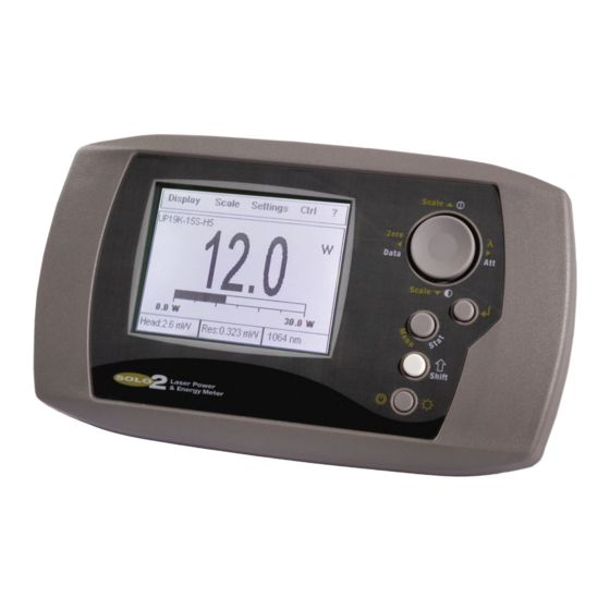
- Page 6 11SOLO2 User’s Manual Revision 0.9 LIST OF ILLUSTRATIONS . 1-1 11SOLO2 F ......................... 9 RONT ANEL . 1-2 11SOLO2 T ........................10 ANEL . 2-1 T ..........................13 HE MENU BAR . 2-2 T ..........................13 HE DIALOG BOX . 2-3 V 11SOLO2 ................
-
Page 7: Introduction
The 11SOLO2 is a microprocessor-based power and energy meter that uses the latest technology to provide a multitude of options in a user-friendly environment. It is a complete power and energy meter. The 11SOLO2 provide a statistical analysis of your measurements. It allows you to store data on the 1- megabyte flash internal memory. -
Page 8: Specifications
The 5µV bias can introduce an error into low power measurements with low sensitivity detectors. It is essential to use the Zero Offset to rezero the 11SOLO2 before making a measurement in these conditions. It is always good practice to use the Zero Offset. See section 2.2. - Page 9 Power Supply Above 3 kHz the monitor will sample points but no log every single point. Maximum if not using any advanced features that require memory. USB cable included. RS-232 cable must be purchased separately. Standa Ltd. All rights reserved...
-
Page 10: Front Panel Description
Pressing the I/O key quickly when the 11SOLO2 is OFF turns the 11SOLO2 ON (do not hold the I/O key). To turn off the 11SOLO2, press and hold the I/O key a few seconds. To prevent battery leakage and to increase battery life, we recommend switching off the 11SOLO2 when not in use. -
Page 11: Top Panel Description
EXTERNAL POWER SUPPLY INPUT JACK: CAUTION Permanent damage may occur to the optical meter if an external power supply other than the Standa P/N 200960A is used. Please call Standa or your local distributor if extra power supplies are needed. - Page 12 Connector type: Female 1/8” jack PROBE INPUT JACK: The 11SOLO2 uses a DB-15 female connector to mate with the detector heads (probes). The 11SOLO2 works with all Standa detectors. It automatically recognizes every power detector head, which ensures accurate auto-calibration.
-
Page 13: How To Use The Keys To Access The Menus
Getting Started This section contains important information concerning the installation and operation of the 11SOLO2. The 11SOLO2 is delivered ready to use. Just insert a detector head in the Probe Input Jack (#5 in Figure 1-2) and press the I/O key. -
Page 14: Quick Power And Energy Measurement Procedure
Fig. 2-2 The dialog box 2.2 Quick power and energy measurement procedure This section applies to all 11SOLO2 versions. It will show you the fastest way of making a laser power and energy measurement with the 11SOLO2 and a Standa power or energy detector. - Page 15 2- First, slide the connector latch to the right to unlock the connector. 3- Turn the 11SOLO2 off and connect a version 5 (or higher) power or energy detector head to the 11SOLO2 using the PROBE INPUT JACK (see Fig. 1-2). It is recommended to turn the 11SOLO2 off before connecting a new head in order to prevent any lost of information from the detector head EEPROM.
- Page 16 The power detectors are thermal sensors sensitive to temperature variations. For high-precision measurements, it is recommended to: • Allow the power detector temperature to stabilize before zeroing the 11SOLO2. • Do not touch the detector head when handling the power detector. Touch only the stand.
-
Page 17: Description Of The Top Level 11Solo2 Menus
You can switch from one option to another without interfering with the measurements. 2.3.1.1 Real time display This display is automatically selected when a head is connected to the 11SOLO2. The top and bottom of the screen shows important settings so you see the conditions as well as the measurement. (see Figure 2-4). -
Page 18: Histogram Display
@ 1064 nm Fig. 2-4 Real time display With a 11SOLO2, you can also choose either the high resolution mode for the most significant digits available or the standard resolution to filter out unimportant fluctuations in measurement. This is a setting in the control (Ctrl) menu of the 11SOLO2. -
Page 19: Statistics Display
(watts) and is inversely proportional to the pulse length. This function is active only in energy mode. The user must enter the pulse width, in picosecond to millisecond units using Settings/Peak Power in the Settings menu. Standa Ltd. All rights reserved... -
Page 20: Status Display
Rate of 10 Hz in this mode. Set the scale higher then your maximum unfiltered measurement because. Take note that if one data point is out of the current scale, the resulting period average will be OUT. Standa Ltd. All rights reserved... -
Page 21: View File
Enter. Move the second vertical lines then select Enter. If you want to exit the zoom option, press the Enter key two times. To disable the zoom, reselect zoom in the display menu. Standa Ltd. All rights reserved... -
Page 22: Digital Tuning Needle Display
It is marked for use with any scale setting in the 11SOLO2. Two different views are available. The first view using Display/Tuning/Standard shows the 0 at the lowest left of the scale as shown below whereas the second view display the 0 in the center of the scale by selecting Display/Tuning/Needle in the Middle. -
Page 23: Settings
Revision 0.9 The checkmark beside the scale number shows the currently selected scale. To change the scale, simply select a scale value from the appropriate range. The 11SOLO2 only shows scale values that fall within the detector head’s range. When in a manually selected scale, you should always use the next higher scale to the measured value, for maximum precision. -
Page 24: Corrections Setting
The 11SOLO2 interpolates a wavelength correction factor using the pre-programmed data in the detector’s EEPROM. Once you have entered a new wavelength in the 11SOLO2, save your settings (refer to 2.3.3.7). This will reload the chosen wavelength and the correction factor automatically, if any, every time you reboot the SOLO2 with the same type of head. -
Page 25: Data Sampling Settings
Use the defaults or select your own sample rate, sample period, and the time period or number of points to do the statistics. You can set the 11SOLO2 either to calculate the statistics for a single sample and stop or to repeat continuously. Take data for a few seconds or a few weeks. - Page 26 If you click start again, the 11SOLO2 will resume the statistics from that point compiling the new measurements with the previous. Click Reset and all the statistical parameters will be cleared and set to zero.
-
Page 27: Fig. 2-13 Data Sampling Parameters Window
Eg. 1 period, 5 hours or 1000 pulses and/or do statistics. Often the Total Duration and Sample Period will be the same but the 11SOLO2 gives you the flexibility for any application. For example with the 11SOLO2 you can see 5 minute averages of your laser performance as you check it during the day and have it stop and hold the last 5 minute statistics after 20 hours. - Page 28 Often the total duration and sample period will be the value same. 0 to 300 time units The 11SOLO2 automatically clears and recalculates the statistics at the end of each sample period unless 0 to 100,000 you manually stop it.
- Page 29 The UP arrow adds units while the DOWN arrow subtracts units. Press the Enter key to validate the selection. 11SOLO2 time will remain as long as the battery lasts. To save your selection, press Done. Exit Mode The user must make a selection here in order to exit Close the data sampling parameters input window.
-
Page 30: Trig Level Setting
To change the Trigger Level value, access the dialog box by selecting Trig Level from the Settings menu and enter the desired number in percentage or in decimals. The 11SOLO2 will not detect pulses with a value under the Trig level. Be careful to select a scale that is close to the measured value if the Trig level is high. -
Page 31: Save And Load User Settings
Settings or Load settings menu items. The display contrast setting is also saved using this option. The saved display contrast is automatically restored the next time the 11SOLO2 is turned on. All the other parameters are automatically loaded only when the same head is connected to the 11SOLO2. -
Page 32: Power Unit
This section gives a complete description of the last group of menus and options available on the 11SOLO2 in the Control and help menus. You can refer to Figure 2-16 at all times for a schematic view of the advanced menu structure. -
Page 33: Control Functions In The Ctrl Menu
11SOLO2 is turned off. You can also select Restore Data from Flash to transfer data from the FLASH back to the RAM memory. This feature is useful when you want to keep the data in the 11SOLO2 until it can be transferred to a computer at a later time or another location. -
Page 34: Ctrl - Statistics Mode
After you have Started and Stopped a data acquisition or restored the data from Flash memory on the 11SOLO2, select Data Transfer in the Ctrl menu or send the serial command *FDL from the PC. This will send your data to the PC. -
Page 35: Ctrl - Energy Mode
2.4.1.6 Ctrl – Energy Mode This function allows you to measure the energy contained in a single pulse with a Standa power detector head. This mode of operation gives access to the same options as in the case of a pyroelectric ⎛... -
Page 36: Ctrl - Anticipation
Standa service. Future help, FAQ, and detector head information will appear here. 2.5 Service If you should need help or additional information on the 11SOLO2 or any Standa products, do not hesitate to contact us. We will be glad to help you. Standa Ltd. All rights reserved... -
Page 37: Installation
Installation for Windows™: Plug the 11SOLO2 into a USB port on the PC. If the PC supports USB 1.1, Windows detects the new device and prompts you for the software drivers. A window will open that says Found New Hardware –... -
Page 38: To Echo Commands
The commands you type will not appear in the HyperTerminal window, unless you set the HyperTerminal up to do so. Only the response from the 11SOLO2 will be displayed. If you prefer to see the commands you are typing, on the HyperTerminal window click the File menu and execute the following sequence: File →... -
Page 39: Traditional Communication Settings
We recommend using the specific serial data acquisition software PCSOLO if no automated acquisition is involved because it is much easier to use. In the case of automated measurement controlled by other software, use the following commands to control the 11SOLO2. They are divided into two groups: •... -
Page 40: Binary Mode Rules
You can program the commands in decimal for sending from the PC. The 11SOLO2 send data in big endian format, that is, the most significant byte comes first. You may need to convert to little-endian depending on the software and computer you are using. - Page 41 Assign the value for the Backlight command to Handle ParameterA = 1 Assign to value for ON to the variable ParameterA SendStringToSerialPort(PackedData, 6) This routine transfers the data found at the address of structure PackedData to the serial port. 6 bytes used. . Standa Ltd. All rights reserved...
-
Page 42: Serial Command Directory
Enable or disable the analog output port. 1150 COMMUNICATIONS COMMANDS Command name Command Description Handle Test Communication Test communication between monitor and PC. 1000 Init Serial Port Change baud rate of the serial port. 1004 Standa Ltd. All rights reserved... -
Page 43: Serial Commands
In binary mode, send the index of the identifier. Remember that the serial protocol is not case-sensitive in text mode. Text Command Binary Command Parameters Return 1130 Scale identifier or index Scale Identifiers: Text Mode Binary Mode Scale Auto optimum 1 picowatt or picojoule Standa Ltd. All rights reserved... - Page 44 300k 300 kilowatts or kilojoules 1meg 1 megawatt or megajoule 3meg 3 megawatts or megajoules 10meg 10 megawatts or megajoules 30meg 30 megawatts or megajoules 100meg 100 megawatts or megajoules 300meg 300 megawatts or megajoules Standa Ltd. All rights reserved...
- Page 45 For example, a 12 milliwatts reading would be displayed like this: Current Value: 0.012 In binary mode, 4 parameters are returned: -the Current Value -the Current Value's unit divider -the Uncorrected Value (raw value before the multipliers and offsets) -the Uncorrected Value's unit divider Standa Ltd. All rights reserved...
- Page 46 Average This value should be divided by the Average Unit. Average Unit This is a divider Standard Deviation This value should be divided by the Standard Dev Unit. Standard Dev Unit This is a divider Standa Ltd. All rights reserved...
- Page 47 File data In text mode, once the command is issued, it is possible to start saving all received data until the terminator is received (the terminator is the character string “EOF” followed by a line feed). Standa Ltd. All rights reserved...
- Page 48 Download data This command is used to send data to the serial port according to the data sampling setting. The maximum transfer speed is 200Hz. Text Command Binary Command Parameters Return None Data in ASCII Standa Ltd. All rights reserved...
- Page 49 (1 or 2) and entering a new value in the second parameter. In binary mode, the value should be multiplied by 10000, and converted into an integer (instead of a floating point value). This is to prevent any cross-platform floating-point conversion error. The following example sets multiplier 2 = 3.3 Standa Ltd. All rights reserved...
- Page 50 The other option available is the Zero-offset. The Zero-offset operation is done first, before those of the Multipliers and Offsets Query Data Sampling Settings This command is used to read the current data sampling settings Text Command Binary Command Parameters Return 1151 Sampling Settings info Settings data: Standa Ltd. All rights reserved...
- Page 51 Text Command Binary Command Parameters Return DSU, 1152, Sample Rate, Sample Rate Unit, Sample Period, Sample Period Unit, Total Duration, Total Duration Unit, Time Stamp(On/Off) Defaults: See Table 2.2 Parameters: Standa Ltd. All rights reserved...
- Page 52 Parameter2 = 0 Parameter3 = 90 Parameter4 = 1 Parameter5 = 1 Parameter6 = 0 Parameter7 = 1 Set Trigger Level This command sets the internal trigger level when using the device in energy reading mode. Standa Ltd. All rights reserved...
- Page 53 Set Energy Mode This command is used to toggle Energy mode when using a wattmeter. Text Command Binary Command Parameters Return 1160 1 to turn On, 0 to turn Off Default: Off Standa Ltd. All rights reserved...
- Page 54 Text Command Binary Command Parameters Return 1001 Version number and device type. The following example is for 11SOLO2 version 1.2. There are four parameters in binary mode. In this case they would be: Binary parameters Example Header: Acknowledge 2 byte word...
- Page 55 In this case they would be: Binary parameters Example Header: Acknowledge 2 byte word Length of transmission (excluding header) 2 byte word Reply parameters: Length of Head name string 4 byte word Detector model name QE-25- 10 bytes SP-MB Standa Ltd. All rights reserved...
- Page 56 100000. ¹ Active Wavelength Currently used Wavelength in nm same Scale Min Power Wattmeters: minimum scale index same (see Set Scale command). (wattmeters) OR Joulemeters: Maximum power Max Power supported by the detector (in Watts). (joulemeters) Standa Ltd. All rights reserved...
- Page 57 1 = On , 0 = Off 27 Currently Logging data Is the analog output enabled? Yes / 1 = On , 0 = Off 28 Analog Output 29 Resolution Resolution of the detector Divide this value by the Resolution Divider Standa Ltd. All rights reserved...
- Page 58 4 byte double word Example Response from 11SOLO2 Text Command: *BAT <enter> The battery power is High Binary Command: Handle = 1006 3 (as one 4 byte word in binary) Set the Internal Clock Standa Ltd. All rights reserved...
- Page 59 This command is used to enable or disable the output of the current value on the analog port of the device. Text Command Binary Command Parameters Return 1150 1 to Enable, 0 to Disable Default: Disabled Standa Ltd. All rights reserved...
- Page 60 11SOLO2 User’s Manual Revision 0.9 COMMUNICATIONS COMMANDS Test Communication This command is used to test communication with your 11SOLO2. The PC is communicating with the monitor if you receive the ACK response. Text Command Binary Command Parameters Return 1000 Init Serial Port This command is used to change the current baud rate of the serial port of the device.
-
Page 61: Error Messages
Make sure the head is a joulemeter before issuing joulemeter specific commands Already logging data Disable before re-enabling File does not exist In order to download a file, first run an acquisition, or load it from the storage media. Standa Ltd. All rights reserved... -
Page 62: Usb Installation For The Solo2
4.1 USB installation for the SOLO2 The 11SOLO2 has a USB type B port. When connected to a PC it emulates a standard serial port. This means that it is possible to connect many 11SOLO2s on one computer, without tying up the ordinary serial ports, while keeping a simple interface that is easy to design software for. -
Page 63: Qea And Qeas
When using an oscilloscope or When using a Standa 11SOLO2, above. Make sure that the energy level is below the detector’s damage threshold and your laser still has a good stability. - Page 64 You can add this to your ± uncertainty when you use the attenuator or try to stabilize the laser and environment and begin again with Step 3. The correction multiplier for the revised 11DUO (rev 2.0), the 11SOLO2 and an Oscilloscope will be given Reading...
-
Page 65: Recycling And Separation Procedure
6.1 Recycling and separation procedure. This section is used by the recycling center when the monitor reaches its end of life. Breaking the calibration seal or opening the monitor will void the 11SOLO2 warranty. The complete Monitor contains 1 Monitor...
Need help?
Do you have a question about the 11SOLO2 and is the answer not in the manual?
Questions and answers