
Subscribe to Our Youtube Channel
Related Manuals for Argus green stream 707

Summary of Contents for Argus green stream 707
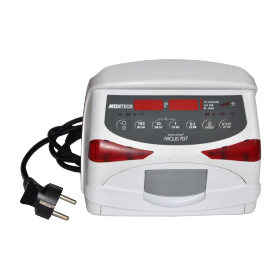
- Page 1 Service Manual for Volumetric Infusion Pump ® green stream ARGUS 707 Made in Switzerland 0120 ARGUS Medical AG, CH-3627 Heimberg / Switzerland (A member of the CODAN group)
-
Page 2: Table Of Contents
5.5. Volume calibration ..........................24 5.6. Pump specifications..........................25 5.7. Fault codes............................26 REPLACEMENT OF PARTS..........................27 6.1. General ...............................27 6.2. Disassembling of the ARGUS 707.....................27 6.3. Replacements of parts ........................31 6.4. Spare parts ............................32 SAFETY STANDARD CHECK..........................36 WIRING DIAGRAMM ............................. 37 BLOC SCHEMATIC.............................. -
Page 3: Introduction
IMPORTANT! This service manual is intended for the exclusive use of authorized persons who have been trained by ARGUS Medical AG in the maintenance and repair of the ARGUS 707 infusion pump. The service manual is meant to be used together with the user manual. -
Page 4: Interrogation Mode
Please refer to chapter 2.6 where the meanings of the addresses are explained. To modify any configuration data you have to go into the configuration mode. 14.164.A_A707en.SM.V1.01.doc ARGUS Medical AG 10.02.04 AS 4 / 38... -
Page 5: Configuration Mode
If the PIN code was accepted the pump will show the display of chapter 2.3.1 again, but you have now access to all writeable addresses in the list of chapter 2.6. Select therefore any address in the left display (see next side): 14.164.A_A707en.SM.V1.01.doc ARGUS Medical AG 10.02.04 AS 5 / 38... - Page 6 Changes in configuration become active, if the pump is switched on normally again. Important remark: Invalid values entered will be corrected automatically by the pump to the maxima or minima value allowed for the according address! 14.164.A_A707en.SM.V1.01.doc ARGUS Medical AG 10.02.04 AS 6 / 38...
-
Page 7: First Activation Of A Configuration Pin Code
Please note: The interrogation mode can always be accessed without the PIN. 2.5. Changing an existing pin code Enter the configuration mode (see chapter 2.3), select address 0 and enter the new pin code. 14.164.A_A707en.SM.V1.01.doc ARGUS Medical AG 10.02.04 AS 7 / 38... -
Page 8: Address List Of The Pump Configuration
W Pressure display with indicator (#45=1) 0=No; 1=Yes W Standby- and battery pre alarm low volume 0=No; 1=Yes W Flashing numeric display at alarm 0=No; 1=Yes W Alarm acknowledge only with key [MODE] 0=No; 1=Yes 14.164.A_A707en.SM.V1.01.doc ARGUS Medical AG 10.02.04 AS 8 / 38... - Page 9 (additional key [STOP] if #4=1) Display brightness (2...15) Buzzer alarm volume (5...10) Battery discharge time incl. 15min pre- (45...300) alarm in [min] Automatic Menu fall back delay time in [s] (5...30) 14.164.A_A707en.SM.V1.01.doc ARGUS Medical AG 10.02.04 AS 9 / 38...
-
Page 10: Special Configuration Options
2. PC configuration tool “AConfig”: With this additional software the pump may be configured from a PC over the serial port. This software may be available from your local distributor or ARGUS Medi- cal AG. Caution: AConfig may only be used with software versions greater or equal to 1.01. -
Page 11: Configuration And History Printout
The connection of the ARGUS 707 over the serial interface RS 232 can be done by con- necting the interface cable no.10.093 to the serial interface outlet of the serial COM port of a PC. -
Page 12: Configuration Printout
3.3. Configuration printout Connect the ARGUS 707 to your PC (see chap. 3.1) and setup the terminal program (see chap. 3.2). Start to capture text on the PC side before you switch the pump on. 1. Enter into the configuration mode (see chapter 2.3). - Page 13 96=0 146=0 196=0 246=0000 296=0000 346=0000 396=0000 47=0 97=0 147=0 197=0 247=0000 297=0000 347=0000 397=0000 48=0 98=0 148=0 198=0 248=0000 298=0000 348=0000 398=0000 49=0 99=0 149=0 199=0 249=0000 299=0000 349=0000 399=0707 14.164.A_A707en.SM.V1.01.doc ARGUS Medical AG 10.02.04 AS 13 / 38...
-
Page 14: History Printout
CONFIGURATION AND HISTORY PRINTOUT 3.4. History printout 3.4.1. General Connect the ARGUS 707 to your PC (see chap. 3.1) and setup the terminal program (see chap. 3.2). Start to capture text on the PC side before you switch the pump on. HISt 1. - Page 15 Pump start Exit setup mode Pump stop (KVO) PC configuration done Rate change PC configuration failure Enter setup mode Pump start, ext. changed parameters No drops, pump stop Upstream occlusion, pump stop 14.164.A_A707en.SM.V1.01.doc ARGUS Medical AG 10.02.04 AS 15 / 38...
-
Page 16: Software Updates
4. SOFTWARE UPDATES 4.1. General This chapter describes the procedure to perform a software update on the ARGUS 707 in- fusion pump. To check the installed software release in your ARGUS 707 press the "MODE" key while switching on the pump. -
Page 17: Maintenance
5.1. General CAUTION! Only authorized persons who have been trained by ARGUS Medical AG or by the local distributor are allowed to service the ARGUS 707 infusion pump. In case of repair request, send the unit to the local distributor with a report outlining the exact nature of the failure. - Page 18 By pressing the key "1" the actual value of the offset voltage in mV is displayed, for the upstream sensor in the left hand display, for the downstream sensor in the right hand display. Return to the original state by pressing the key "1" again. 14.164.A_A707en.SM.V1.01.doc ARGUS Medical AG 10.02.04 AS 18 / 38...
- Page 19 By pressing the key "1" the pump display changes to “xxxx Pr S” where the left display shows the actual upstream pressure sensor signal in mV. Return to the original state by pressing the key "1" again. 14.164.A_A707en.SM.V1.01.doc ARGUS Medical AG 10.02.04 AS 19 / 38...
- Page 20 By pressing the key "1" the pump display changes to “Pr S xxxx” where the right display shows the actual downstream pressure sensor signal in mV. Return to the original state by pressing the key "1" again. 14.164.A_A707en.SM.V1.01.doc ARGUS Medical AG 10.02.04 AS 20 / 38...
- Page 21 By pressing the key "1" the pump display changes to “Pr S xxxx” where the right display shows the actual downstream pressure sensor signal in mV. Return to the original state by pressing the key "1" again. 14.164.A_A707en.SM.V1.01.doc ARGUS Medical AG 10.02.04 AS 21 / 38...
- Page 22 Return to the original state by pressing the key "1" again. The procedure for the upstream sensor calibration part 2 is equal to the proce- dure for the downstream sensor, but with inverse delivery direction. 14.164.A_A707en.SM.V1.01.doc ARGUS Medical AG 10.02.04 AS 22 / 38...
-
Page 23: Pressure Control Measurement
If the result of this control measurement does not fulfil the stated requirement, a pressure calibration according to chapter "Pressure calibration" has to be done. 14.164.A_A707en.SM.V1.01.doc ARGUS Medical AG 10.02.04 AS 23 / 38... -
Page 24: Volume Calibration
“START”; then switch the pump off. 8. Perform a control measurement according to the steps 2 & 3 above. Repeat the calibration procedure if necessary. 14.164.A_A707en.SM.V1.01.doc ARGUS Medical AG 10.02.04 AS 24 / 38... -
Page 25: Pump Specifications
11. Perform a control measurement with an infusion rate of 250 ml/h and an infu- sion total of 15 ml. Repeat the calibration procedure if necessary. 5.6. Pump specifications Please refer to the user manual for the specifications (chapter 8). 14.164.A_A707en.SM.V1.01.doc ARGUS Medical AG 10.02.04 AS 25 / 38... -
Page 26: Fault Codes
Infused sum <> Calculated sum (Rotations) F_55 Frequency calculation F_57 Rotation (SW overflow) F_58 Volsum control We recommend replacing the main board in case a fault code is not included in this list above. 14.164.A_A707en.SM.V1.01.doc ARGUS Medical AG 10.02.04 AS 26 / 38... -
Page 27: Replacement Of Parts
6. REPLACEMENT OF PARTS 6.1. General CAUTION! The ARGUS 707 may only be used with accessories and spare parts which have been approved by ARGUS Medical AG for safe technical use. CAUTION! If a door, a housing, a pressure sensor or a main board is replaced, a full calibration (pressure sensors and volume calibration) is required. - Page 28 2. Pull the shaft towards the centre. Repeat point 1 and 2 for the other side of the door and then remove the door. 6.2.3. Disassembling the pump unit 1. Unscrew these screws. Remove the pump unit. 14.164.A_A707en.SM.V1.01.doc ARGUS Medical AG 10.02.04 AS 28 / 38...
- Page 29 (torque 1.0 Nm)! 3. Reinstall the door. Make sure that a washer has been in- stalled on each side! 4. Make sure that this part touches nowhere, oth- erwise noises may be generated! 14.164.A_A707en.SM.V1.01.doc ARGUS Medical AG 10.02.04 AS 29 / 38...
- Page 30 7. Use the short screw at these places (torque 1.1 Nm)! 7. Use the long screw at these places (torque 1.1 Nm)! 14.164.A_A707en.SM.V1.01.doc ARGUS Medical AG 10.02.04 AS 30 / 38...
-
Page 31: Replacements Of Parts
6.3. Replacements of parts CAUTION! The ARGUS 707 may only be used with accessories and spare parts which have been approved by ARGUS Medical AG for safe technical use. For the part numbers of replacement parts consult the following chapter. -
Page 32: Spare Parts
REPLACEMENT OF PARTS 6.4. Spare parts 10.087 Combination clamp 10.089 External drop detector 10.120 Display board A707 10.093 Interface cable docking pumps 10.121 Pressure sensor 10.122 Air detector A707 A707 14.164.A_A707en.SM.V1.01.doc ARGUS Medical AG 10.02.04 AS 32 / 38... - Page 33 REPLACEMENT OF PARTS 10.123 Stop flow A707 10.124 Main board A707 10.125 Sensor board A707 10.126 Pump unit A707 10.127 Door complete A707 14.164.A_A707en.SM.V1.01.doc ARGUS Medical AG 10.02.04 AS 33 / 38...
- Page 34 230VAC complete 10.137 Casing forepart 10.129 Casing forepart (without door) complete 12.042 Cable staff alert 2m 12.011 Interface cable 8pol/2m & 12.012 Interface adapter 10.119 Battery NiMHd 12V/1500mAh A707 11.221 Sealing A707 14.164.A_A707en.SM.V1.01.doc ARGUS Medical AG 10.02.04 AS 34 / 38...
- Page 35 11.245 Short instruction Portuguese 11.239 Short instruction German 11.246 Short instruction Spanish 11.240 Short instruction English 11.247 Short instruction Italian 11.241 Short instruction French 11.242 Short instruction Danish 11.243 Short instruction Dutch 14.164.A_A707en.SM.V1.01.doc ARGUS Medical AG 10.02.04 AS 35 / 38...
-
Page 36: Safety Standard Check
SAFETY STANDARD CHECK 7. SAFETY STANDARD CHECK The safety check should be done at least every 10’000 running hours or every 24 months. Refer to the form in the appendix of this manual. 14.164.A_A707en.SM.V1.01.doc ARGUS Medical AG 10.02.04 AS 36 / 38... -
Page 37: Wiring Diagramm
512 Hz (Motor + Buzzer) Ext. DC Li-Batt. 3 Volt + 5V Air Bubble Detector (Logic) Ni-Cd Akku 12V Drop Detector Pressure Sensor (in) Door Control Pressure Sensor (out) Motion Control 14.164.A_A707en.SM.V1.01.doc ARGUS Medical AG 10.02.04 AS 37 / 38... -
Page 38: Appendix
(all measurements made with a power cable 2.5 m) Charge the battery after this test! The pump has passed the SSC and is safe for use Date: ………………..…………………………………………………………………….. Name: ………………..…………………………………………………………………….. Signature: ………………..…………………………………………………………………….. 14.164.A_A707en.SM.V1.01.doc ARGUS Medical AG 10.02.04 AS 38 / 38...
Need help?
Do you have a question about the green stream 707 and is the answer not in the manual?
Questions and answers