Advertisement
Quick Links
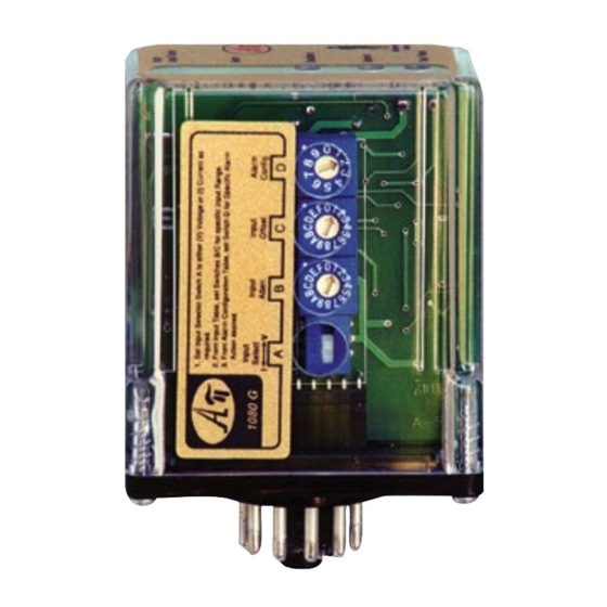
DC Input Alarm Trips, Isolated, Field Configurable
Input:
0-50 mV to ±10 VDC, 0-1 mA to 4-20 mADC
Output:
One 8 Amp DPDT Relay or Two 8 Amp SPDT Relays
O One Minute Setup for 24 Input Ranges
O Switch Selectable Relay Configuration
O Adjustable Setpoint and Deadband
O Input LoopTracker
®
and Alarm Status LEDs
O Hot Swappable Plug In Design
O Alarm Test / Reset Button
O Built-In Loop Power Supply for Sink/Source Input
Applications
Q Process Limit Backup Alarm
Q Tank Level Alarm
Q Process Signal Over, Under, Out-of-Range Alarm
DC Input Ranges
24 switch selectable ranges. See table on other side.
Voltage:
0-50 mVDC to 0-10 VDC
Bipolar voltage:
±5 VDC or ±10 VDC
Current:
0-1 mADC to 0-20 mADC, 4-20 mADC
Input Impedance, Burden, Protection
Voltage:
250 kΩ minimum
50 Ω typical (1 VDC burden at 20 mA)
Current:
Common mode protection: 750 VAC
or 750 VDC
p
Input Loop Power Supply
18 VDC unregulated, 25 mADC, <1.5 V
p-p
May be selectively wired for sinking or sourcing mA input
LoopTracker
Variable brightness LED indicates input loop level and status
API 1080 G Relay Output
Two SPDT form C contact sets operating in unison as one
DPDT contact set
One 12 turn setpoint potentiometer, 0-100% of span
One 12 turn deadband potentiometer, 1-100% of span
Field configurable alarm type, action, and latching
API 1090 G Relay Output
Two independent SPDT form C contact sets
Two 12 turn setpoint potentiometers, 0-100% of span
Two 12 turn deadband potentiometers, 1-100% of span
Field configurable alarm type, action, and latching
Relay Contact Rating
8 A @ 240 VAC resistive load or 30 VDC resistive load max.
Caution: Do not exceed socket voltage rating
Use an RC snubber for inductive loads
AC inductive load
AC resistive
(cos f = 0.4)
8
5
3
DC inductive load
1
(L/R = 7 ms)
0.5
DC resistive
0.3
load
0.1
0
3 5 10
30 50 100 300 500
Switching Voltage (V)
Relay Contact Ratings
Output Test/Reset Button
Toggles relay to opposite state when pressed
Resets latching relay if latching relay mode is selected
Response Time
70 milliseconds typical
Ambient Temperature Range and Stability
–10°C to +60°C operating ambient,
Better than 0.02% of span per °C stability
Housing and Sockets
IP 40, requires installation in panel or enclosure
API 011 or API 011 FS socket
Socket mounts to 35 mm DIN rail or can be surface mounted
Power
Standard:
115 VAC ±10%, 50/60 Hz, 2.5 W max.
P option:
85-265 VAC 50/60 Hz, 60-300 VDC, 2.5 W typ.
A230 option: 230 VAC ±10%, 50/60 Hz, 2.5 W max.
D option:
9-30 VDC, 2.5 W typical
www.mod-tronic.com | sales@mod-tronic.com | 1-800-794-5883
Variable Brightness Input LED
Bi-Color Relay LED
Deadband Adjustment
Setpoint Adjustment
Output Test Button
Quick Link
api-usa.com/1080
Variable Brightness Input LED
Bi-Color Relay 2 LED
Bi-Color Relay 1 LED
Deadband 2 Adjustment
ripple
Deadband 1 Adjustment
Setpoint 2 Adjustment
Setpoint 1 Adjustment
Output Test Button
Quick Link
api-usa.com/1090
Description
The API 1080 G and API 1090 G accept a DC voltage or cur-
rent input and provide visual alarm indication and alarm relay
contact outputs. Voltage and current input ranges can be
field-configured via external rotary and slide switches. Offset
ranges such as 1-5 VDC and 4-20 mADC are also included.
Heavy-duty relay contacts allow the module to directly control
high capacity loads. Top-accessible potentiometers are used
to adjust the alarm setpoint from 0 to 100% and the deadband
from 1 to 100%.
The API 1080 G provides a single setpoint adjustment of the
two DPST relay contacts. The alarm output can be field con-
load
figured for HI or LO operation, latching or non-latching, and
normal or reverse acting. The deadband and alarm setpoint
are adjustable.
The API 1090 G provides two setpoint adjustments of the two
SPDT relay contacts. The alarm outputs can be configured in
the field for HI/HI, LO/LO, HI/LO or LO/HI operation, latching
or non-latching, and normal or reverse acting. Deadband and
alarm setpoints are independently adjustable for each alarm.
Model
API 1080 G
API 1080 G A230
API 1080 G P
API 1080 G D
API 1090 G
API 1090 G A230
API 1090 G P
API 1090 G D
Option—add to end of model number
U
Conformal coating for moisture resistance
Accessories—order as separate line item
API 011
11-pin socket, DIN rail or surface mount
API 011 FS 11-pin finger safe socket, DIN rail or surface mount
API CLP1
Module hold-down spring for high vibration or
mobile applications
2.38"
1.75"
API 1080 G
H H H H H H
H H H H H
H H H H H H
H H H H H
H H H H H H
H H H H H
H H H H H H
H H H H H
H H H H H H
Made in USA
2.38"
1.75"
API 1090 G
Input
Field configurable
Single setpoint field configurable
specify range if factory is to set
switches
specify configuration for factory setup
Field configurable
specify range if factory is to set
switches
specify configuration for factory setup
API 1080 G, API 1090 G
1
Minute
Setup!
Sink/Source Input and Loop Supply
For maximum versatility, a current input can be selectively
wired for sinking or sourcing. This allows the API 1080 G and
API 1090 G to work with powered or unpowered mA inputs.
An unregulated 18 VDC loop excitation supply can be used
to power passive input devices eliminating the need for an
additional DC loop supply.
LoopTracker and Alarm Status LEDs
API exclusive features include a LoopTracker LED that varies
in intensity with changes in the process input signal. A red/
green bi-color alarm status LED (two on the API 1090) visually
indicate alarm status. These LEDs provide a quick visual status
of your process at all times.
Output Test / Unlatch
API's exclusive functional test button can be used to verify the
alarm and system operation. The output test button greatly
aids in saving time during initial startup and/or troubleshooting.
The HT latching option provides the additional function of
unlatching the alarm when the reset button is pressed. The
alarm will reset if the alarm condition not longer exists.
Output
DPDT relay configuration,
85-265 VAC or 60-300 VDC
2 setpoint field configurable
2 SPDT relays,
85-265 VAC or 60-300 VDC
API 011 FS
API 011
300 V Rating
300 V Rating
2.75"
Hot Swappable
Plug-In Design
Free Factory
I/O Setup!
2.75"
Power
115 VAC
230 VAC
9-30 VDC
115 VAC
230 VAC
9-30 VDC
API CLP1
Advertisement

Related Manuals for Absolute Process Instruments API 1080 G


Summary of Contents for Absolute Process Instruments API 1080 G
- Page 1 Sink/Source Input and Loop Supply Field configurable alarm type, action, and latching The API 1080 G and API 1090 G accept a DC voltage or cur- For maximum versatility, a current input can be selectively API 1090 G Relay Output rent input and provide visual alarm indication and alarm relay wired for sinking or sourcing.
- Page 2 0-5 V V 5 1 Normal Normal acting alarms energize the relay coils in a non-alarm API 1080 G Alarm States with Normal Action HI Alarm 0-10 V V 6 1 Reverse A condition and de-energize them in an alarm condition. This will ±5 V...
Need help?
Do you have a question about the API 1080 G and is the answer not in the manual?
Questions and answers